Note: Descriptions are shown in the official language in which they were submitted.
CA 02564675 2006-10-26
WO 2005/106816 PCT/US2005/013961
ELECTRONIC ARTICLE TRACKING SYSTEM
FOR RETAIL RACK USING LOOP ANTENNA
SPECIFICATION
BACKGROUND OF THE INVENTION
The present invention is directed to electronic article security and tracking
systems
which use resonant security/tracking tags.
Electronic article security (EAS) systems for tracking as well as detecting
and
preventing theft or unauthorized removal of articles or goods from retail
establishments
and/or other facilities have become widespread. In general, such security
systems
employ a security tag which is secured to or associated with an article (or
its packaging).
Such an article is typically readily accessible to potential customers or
facility users and,
therefore, is susceptible to unauthorized removal. Security tags may take on
many
different sizes, shapes and forms depending upon the particular type of EAS
system in
use, the type and size of the article to be protected, the packaging for the
article, etc. In
general, such EAS systems are employed for detecting the presence (or the
absence)
of a securitytag and, thus, a protected article within a surveilled security
area or detection
zone. With respect to use for preventing theft, in most cases, the detection
zone is
located at or around an exit or entrance to the facility or a portion of the
facility.
With respect to tracking, for example, articles of clothing available for sale
in a
retail establishment, it may be desirable to track the physical location of
such articles of
clothing within the establishment. For example, it may be desirable to track
when each
individual article of clothing is removed from a fixture, such as a metal
clothing rack, to
obtain data to be used, for example, for manufacturing additional quantities
of articles of
clothing that receive the most customer attention based on data related to
removal of
such articles from the fixture.
However, the use of conventional radio frequency identification (RFID)
technology
to track articles of clothing in retail environments is difficult due, in
part, to the display
fixturing used for the clothing. Metal clothing racks or fixtures tend to
interfere with
antennas placed in walls or ceilings near clothing being displayed. Further,
the
movement of clothing on rolling racks or fixtures presents a challenge in the
placement
-1-
CA 02564675 2006-10-26
WO 2005/106816 PCT/US2005/013961
of antennae for article tracking. As the need increases to track garments
within a retail
space, rather than tracking garments just at store exits, placement of
antennae is
increasingly difficult.
One type of EAS system which has gained widespread popularity utilizes a
security tag which includes a self-contained, passive resonant circuit in the
form of a
small, generally planar printed circuit which resonates at a predetermined
detection
frequency within a detection frequency range. A transmitter, which is also
tuned to the
detection frequency, is employed for transmitting electromagnetic energy into
the
detection zone. A receiver, tuned to the detection frequency, is positioned
proximate to
the detection zone. When an article having an attached security tag moves into
or
passes through the detection zone, the security tag is exposed to the
transmitted energy,
resulting in the resonant circuit of the tag resonating to provide an output
signal
detectable by the receiver. The detection of such an output signal by the
receiver
indicates the presence of an article with a security tag within the detection
zone.
Recently, passive resonant security tags which return unique or semi-unique
identification codes were developed. U.S. Pat. No. 5,446,447 (Carney et al.),
U.S. Pat.
No. 5,430,441 (Bickley et al.), and U.S. Pat. No. 5,347,263 (Carroll et al.)
disclose three
examples of such security tags. These securitytags typically include an
integrated circuit
to generate the identification code. Such "intelligent" security tags provide
additional
information about the article detected in the zone of the interrogator.
It would be desirable to use such passive resonant security tags or even
active
resonant security tags which return unique or semi-unique identification codes
in an
article tracking system where there is minimal interference from metal
clothing racks or
fixtures and where antenna placement difficulties due to movement of rolling
racks or
fixtures are minimized.
All references cited herein are incorporated herein by reference in their
entireties.
BRIEF SUMMARY OF THE INVENTION
A fixture for use in a retail store is provided which includes a loop formed
from a
conductive material and which is adapted to support hanging articles. The loop
has a first
and second end. The first and second ends of the loop are each connected to an
insulator member where the first end is electrically insulated from the second
end by the
-2-
CA 02564675 2006-10-26
WO 2005/106816 PCT/US2005/013961
insulator member. An RFID reader is connected to each of the first end and the
second
end of the loop. A circuit is formed by the loop and the RFID reader wherein
the loop
provides an antenna function for the RFID reader.
The fixture may include a base and may include wheels. The fixture may be, for
example, in the form of a vertical loop, a horizontal loop, may be adapted for
suspension
from a ceiling or may be mounted over a table. The circuit formed is
preferably adapted
to operate in the UHF or HF spectra.
Preferably, the RFID reader is operable from at least one rechargeable
battery.
The battery may be rechargeable by use of, for example, a standard AC outlet,
solar
cells, power generated by action from wheels attached to the fixture, or a
proximity
recharger. Preferably, the RFID reader includes a standby mode wherein full
power is
substantially reduced to conserve battery power except during scheduled
intervals during
which reading occurs or except during intervals when an operator or network
makes a
specific inquiry to the RFID reader. Preferably, the loop is constructed of
metal, which
may or may not be insulated, to accommodate long-term exposure or safety
considerations. A plurality of loops may be included on the fixture that are
operable to
support articles, for example, by hangers. For example, the fixture may
include at least
two racks wherein the loops are parallel to one another or perpendicular to
one another.
A single RFID reader or multiple RFID readers may be used when multiple loops
are
used. The loops may or may not be isolated from one another when multiple
loops are
used. The loop may be adapted to create a far-field cancellation of antenna
pattern. The
loop may be crossed to create an intersection in the loop to create a far-
field cancellation
antenna pattern.
A method of retrofitting a fixture for use in a retail store is also provided
which
comprises the steps of providing at least one loop formed from a conductive
material
where the loop is adapted to support retail articles, opening a gap in the
loop to yield a
first end and a second end of the loop, inserting an insulating member in the
gap, and
electrically connecting an RFID reader between the first end and the second
end of the
loop to form a circuit including the loop and the RFID reader wherein the loop
provides
an antenna function for the RFID reader.
Preferably, the method includes the step of providing a base for the at least
one
loop. Wheels may be included on the base. The step of providing the loop may
include
-3-
CA 02564675 2006-10-26
WO 2005/106816 PCT/US2005/013961
providing a vertically oriented loop or a horizontally oriented loop,
suspending the loop
from a ceiling or mounting the loop over a table. The step of providing the
loop may also
include providing several loops for the fixture. For example, the two parallel
or two
perpendicular loops may be provided. The step of electrically connecting the
RFID
reader may include connecting one RFID reader to at least two of the plurality
of loops.
The loops may or may not be isolated from one another. The method may include
the
step of creating a far-field cancellation of antenna pattern. The method may
also include
the step of crossing the loop to create an intersection in the loop to create
a far-field
cancellation antenna pattern.
BRIEF DESCRIPTION OF SEVERAL VIEWS OF THE DRAWINGS
The invention will be described in conjunction with the following drawings in
which
like reference numerals designate like elements and wherein:
FIG.1 is an isometric view of a fixture having a built-in loop antenna in
accordance
with one preferred embodiment of the present invention;
FIG. 2 is a block diagram schematic of an RFID tag suitable for use with the
present invention;
FIG. 3 is a functional block diagram schematic of a reader (i.e., an
interrogator)
suitable for use with the present invention;
FIG. 4 is an isometric view of a fixture having a pair of built-in loop
antennae in
accordance with a second preferred embodiment of the present invention;
FIG. 5 is an isometric view of a fixture having three built-in loop antennae
in
accordance with a third preferred embodiment of the present invention;
FIG. 6 is an isometric view of a fixture having a built-in loop antenna in
accordance
with a fourth preferred embodiment of the present invention;
FIG. 7 is an isometric view of a fixture having a built-in loop antenna in
accordance
with a fifth preferred embodiment of the present invention;
FIG. 8 is an isometric view of a fixture having a built-in loop antenna in
accordance
with a sixth preferred embodiment of the present invention;
FIG. 9 is an isometric view of a fixture having a built-in loop antenna in
accordance
with "a seventh preferred embodiment of the present invention; and
-4-
CA 02564675 2006-10-26
WO 2005/106816 PCT/US2005/013961
FIG. 10 is an isometric view of a fixture having a built-in loop antenna in
accordance with an eighth preferred embodiment of the present invention.
DETAILED DESCRIPTION OF THE INVENTION
The present invention is directed to electronic article security and tracking
systems
which use resonant security/tracking tags. Typically, clothing fixtures are
made of metal
and, therefore, with minimal modification can be retrofitted or be newly
constructed to
become "smart." For example, smart fixtures such as "smart racks," "smart
rails" or
"smart tables," as will be described herein, may be manufactured or existing
fixtures of
these types can be retrofitted. The fixtures or parts of the fixtures could
become
antennae for use in RFID that operate in the UHF (e.g. 915 MHz) and/or HF
spectra (e.g.
13.56 MHz).
For the purpose of the present invention, the terms "rack" and "fixture" are
intended to be synonymous and are intended to broadly include all types of
racks,
fixtures, or any other type of similar object used to support items sold at a
retail store.
For example, a rolling rack for clothing on hangers can be modified to be a
large
detection loop antenna. To transform an existing rack into "smart" rack, a
break in the
loop must be created that can be attached to an RFID reader or interrogator.
For
purposes of the present invention, a "reader" is synonymous with an
"interrogator." The
reader provides RF energy to energize transponder tags on or in the clothing
articles.
In the past, "smart shelves" have existed wherein a separate antenna is
affixed to
an architectural or furniture feature. By this invention, the physical
function of the rack
and the electrical function of antenna are achieved by the same object (i.e.,
the fixture).
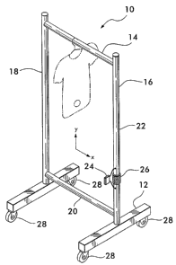
Referring now to the drawings wherein like part numbers refer to like elements
throughout the several views, there is shown in FIG. 1 a fixture for use in a
retail store 10
in accordance with one preferred embodiment of the present invention. The
fixture 10
comprises a loop 22 which includes a base 12, a hanger bar 14, upright members
16,18,
and bottom support member 20. The hanger bar 14, upright members 16,18 and
bottom
support member 20 form the loop 22 of conductive material that form an
antenna, as will
be further discussed below. The fixture 10, as shown in FIG. I is similar to a
standard,
prior art rolling rack with certain modifications such that loop 22 is formed
into an
antenna. The fixture 10 of FIG. 1 depicts a simple smart rack, where the rack
is
-5-
CA 02564675 2006-10-26
WO 2005/106816 PCT/US2005/013961
attached to an RFID reader (interrogator) 24 by the insertion of an insulated
spacer 26.
Optionally, as shown, the base 12 of the rack 10 may have wheels 28 for
assistance in movement of the rack 10 within a retail establishment.
FIG. 2 shows general details of a sample RFID tag 30 suitable for use with the
present invention. The RFID tag 30 becomes an intelligent security tag when
used in
embodiments wherein the tag 30 is attached to articles. The tag 30 includes a
passive
resonant radio frequency (RF) circuit 32 for use in detecting when the tag 30
is within a
zone monitored by a reader or interrogator, as is well-known in the art. One
well-known
type of circuit 32 has a coil antenna 34 and a capacitor 36 which togetherform
a resonant
circuit with a predetermined resonant frequency, i.e., the selected radio
frequency
determined by the values of the coil and the capacitor. Power for the tag 30
is derived
from the antenna 34 in a conventional manner. Furthermore, the tag 30 includes
an
integrated circuit (IC) 38 for providing "intelligence" to the tag 30. The IC
38 is electrically
connected to the resonant circuit 32. The capacitor 36 may be either external
to the IC
38, or the capacitor 36 may be within the IC 38, depending upon the desired
implementation of the circuit 32. The IC 38 includes a programmable memory 40,
such
as a twenty bit memory, for storing bits of identification data. The IC 38
outputs a data
stream comprised of the stored data (e.g. twenty bits in the present
embodiment) when
sufficient power from the antenna 34 is applied thereto. In one embodiment of
the
invention, the data stream creates a series of data pulses by switching an
extra capacitor
(not shown) across the coil antenna 34 for the duration of the data pulses.
The addition
of the extra capacitor changes the resonant frequency of the RF circuit 32,
detuning it
from the operational frequency. Thus, instead of the RF circuit 32 returning a
simple
single frequency response signal, it returns a signal containing a packet of
preprogrammed information. The packet of information (data pulses) is received
and
processed by interrogator receiving circuitry and is decoded (if necessary) to
provide
identification information about an article to which the tag 30 is secured.
Other methods
of using the data in the IC memory 40 to output identification data from the
tag 30 are
within the scope of the invention. The IC 38 is preferably also a passive
device and is
powered in the same manner as the RF circuit 32 (i.e., by using energy
received at the
antenna 34 from the interrogator transmitter signal). The tag 30 is thus a so-
called "radio
frequency identification (RFID) tag.". Other types of RFID tags may be used
with the
-6-
CA 02564675 2009-12-18
present invention such as RFID tags that use a tuned antenna (e.g.,.a.dipole
antenna)
as an alternative to the RF circuit 32 where ultrahigh frequencies (UHF) are
used, such
as 915 MHz. Examples of other RFID tags which are suitable for use as the tag
30 are
shown in U.S. Pat. No. 5,446,447 (Carney et al.), U.S. Pat. No. 5,430,441
(Bickley et al.),
and U.S. Pat. No. 5,347,263 (Carroll et al.). Typically, RFID tags are not
physically
deactivatable. In other words, no physical change or change of magnetic state
occurs
to the state of the coil, capacitor or any other element comprising the
antenna circuit of
such RFID tags. An RFID tag which is not physically deactivatable has
significant
advantages over physically deactivatable magnetic security tags and/or prior
art
physically deactivatable RF security tags which are commonly used today
because such
RFID tags are more difficult to bypass. In some embodiments of the present
invention,
nonphysically deactivatable RFID tags are used. In other embodiments of the
present
invention, physically deactivatable RFID tags are used.
FIG. 3 is a block diagram schematic of a reader or interrogator 42 suitable
for use
with the tag 30 described in FIG. 2. The interrogator 42 and the tag 30
communicate by
inductive coupling, as is well-known in the art. The interrogator 42 includes
a transmitter
44, receiver 46, antenna assembly 48, and data processing and control
circuitry 50, each
having inputs and outputs. The output of the transmitter 44 is connected to a
first input
of the receiver 46, and to the input of the antenna assembly 48. The output of
the
antenna assembly 48 is connected to a second Input of the receiver 46. A first
and a
second output of the data processing and control circuitry 50 are connected to
the input
of the transmitter 44 and to a third input of the receiver 46, respectively.
Furthermore,
the output of the receiver 46 is connected to the input of the data processing
and control
circuitry (DPCC) 50. The DPCC 50 then transmits an output signal to a computer
or
database 55 where it is used to check states, locations, etc. It is within the
broadest
scope of the invention to have the DPCC 50 transmit the output signal
wirelesssly to a
remote computer or database 55. Interrogators having this general
configuration may be
built using circuitry described in U.S. Pat. Nos. 3,752,960, 3,816,708,
4,223,830 and
4,580,041, all issued to Walton.
Alternatively, where UHF or microwave frequencies are used, the RFID reader
may be implemented using a UHF/microwave reader, such as the SX2000 by WJ
Communications, Inc. of San Jose, California.
-7-
CA 02564675 2006-10-26
WO 2005/106816 PCT/US2005/013961
Fixtures such as racks have an advantage over flat shelves or pedestals in
that
multiple loops may be placed, for example, perpendicular to each other to
achieve better
coverage of tags distributed in random orientations. For example, as seen in
FIG. 4, an
additional embodiment of the present invention is shown that enhances of the
fixture's
operation by the addition of a second loop in the y, z plane. The fixture 10A
of FIG. 4
includes a base 12A, a hanger bar 14A, upright members 16A and 18A, bottom
support
member 20A, loop 22A, RFID reader 24A, insulated spacer 26A and wheels 28A.
Additionally, a second loop 52 is shown that is mounted to the hanger bar 14A
and
bottom support member 20A. This second loop 52 provides for clothing to be
hung in
on the primary hanger bar 14A and the second loop hanger bar 54. Again, as in
the loop
22A, loop 52 includes an RFID reader 56 and insulated spacer 58 similar to the
reader
24A and spacer 26A of loop 22A. For clarity of illustration, this loop 52 is
depicted in the
center of the span of the hanger bar 14A. As shown, FIG. 4 depicts two RFID
readers.
However, a single RFID reader may be multiplexed between loops. It is noted
that direct,
unmultiplexed connection of an RFID reader to two or more loops is inferior in
practice.
The two loops 22A, 52 of FIG. 4 are depicted as being completely isolated (see
insulators
53A and 53B), but this need not be the case. Sharing of a single node is
permissible.
Examples of other embodiments of the present invention are shown, for example,
in the fixtures 10B, 10C, 10D, 10E and IOF of FIGS. FIGS. 5-9, respectively.
The
specific details of these particular embodiments are not fully described, but
suffice it to
say that the basic elements are of a substantially identical configuration to
that of FIGS.
1 and 4. As shown in FIG. 5, a fixture 10B is provided having loops 60, 62 at
each end
of the fixture I OB, or three loops with one at each end and another at the
center of the
rack (not shown). As shown in FIG. 6, a fixture 10C is provided that is
designed for
hanging garments over a table top 64. Here, loop 66 is shown where the
elements of the
loop are mounted to the table top (here, shown in an optional under-the-table
top
configuration). As shown in FIG. 7, a fixture 10D is provided where the loop
68 for
hanging garments is mounted to a ceiling 70. As shown in FIG. 8, a fixtures
IOE is
provided where the loop 72 for hanging garments is mounted to a wall 74.
Clothing may
be hung on the structure forming the loop 72 itself or on the hanger bar 76.
Similarly, as
shown in FIG. 9, a fixture 10F is provided where garments again maybe either
hung on
-8-
CA 02564675 2006-10-26
WO 2005/106816 PCT/US2005/013961
the structure of the loop itself or on a hook system 78. These latter two
systems do not
have the advantage of portability.
Another alternate embodiment of the present invention is shown in fixture 10G
of
FIG. 10. Fixture 10G is similar to that of FIG. I except that it is in
generally a "figure 8"
configuration, i.e., a paired loop configuration, having, effectively, two
loops, rather than
a single loop. With each set of paired leads, one lead forms an "active"
antenna loop.
The other lead forms a "passive" loop, i.e., one which is not driven or
driving, but interacts
with the respective loop only through mutual coupling between them.
As can bee seen in FIG. 10, the upright members 90, 92 extend upwardly, then
cross at intersection 94. This crossing over of the loop 96 is what creates
far-field
cancellation of the antenna patterns, as well as reduces interference from
remote
sources of extraneous radio frequency energy. This technique of crossing over
is well
known as shown, for example, in U.S. Patent No. 5,103,235 (Clemens), the
complete
specification of which is fully incorporated by reference hereto.
It is intended that the scope of the present fixturing invention include
providing the
ability to hang clothing as well as a variety of other retail merchandise not
necessarily
specified herein.
Further embodiments of the system of the present invention include the use of
fixtures having RFID readers that are battery powered and recharged by a
standard
power cord, and/or, for example, with solar cells 80 (FIG. 6), power
generation from
wheel action 82, or proximity rechargers similar to those used for electronic
toothbrushes
(not shown). These charging systems may be integrated into the RFID reader and
are
well known in the art of battery powered systems.
Low average power consumption can be achieved via low duty factor, with
reading
occurring, for example, only at scheduled intervals or in response to operator
or network
inquiries.
Synchronization issues with other readers can be achieved via wireless
slaving,
timed interleave for non-interference, or protocol extensions to accommodate
inter-reader
communication via the tag communication channel.
The rack material (including, for example, hanger bar 14, upright members 16,
18
and bottom support member 20 of FIG.1 and similar elements in the other
embodiments
-9-
CA 02564675 2006-10-26
WO 2005/106816 PCT/US2005/013961
shown herein) may be left as bare metal or coated with insulation to
accommodate any
long term exposure or safety considerations.
The precise dimensions of the various loops described in the various
embodiments
and the amount of power required for each of these loops may vary
considerably.
However, such dimensions and requirements regarding power are well within the
knowledge of one skilled in the art of antenna design.
While the invention has been described in detail and with, reference to
specific
embodiments thereof, it will be apparent to one skilled in the art that
various changes and
modifications can be made therein without departing from the spirit and scope
thereof.
-10-