Language selection

Search

Patent 2566597 Summary

Third-party information liability

Some of the information on this Web page has been provided by external sources. The Government of Canada is not responsible for the accuracy, reliability or currency of the information supplied by external sources. Users wishing to rely upon this information should consult directly with the source of the information. Content provided by external sources is not subject to official languages, privacy and accessibility requirements.

Claims and Abstract availability

Any discrepancies in the text and image of the Claims and Abstract are due to differing posting times. Text of the Claims and Abstract are posted:

  • At the time the application is open to public inspection;
  • At the time of issue of the patent (grant).
(12) Patent: (11) CA 2566597
(54) English Title: CUTTING TOOL INSERT
(54) French Title: PIECE RAPPORTEE D'OUTIL DE COUPE
Status: Deemed expired
Bibliographic Data
(51) International Patent Classification (IPC):
  • B23B 27/14 (2006.01)
(72) Inventors :
  • ACHILLES, ROY DERRICK (South Africa)
(73) Owners :
  • BAKER HUGHES INCORPORATED (United States of America)
(71) Applicants :
  • ELEMENT SIX (PTY) LTD. (South Africa)
(74) Agent: NORTON ROSE FULBRIGHT CANADA LLP/S.E.N.C.R.L., S.R.L.
(74) Associate agent:
(45) Issued: 2011-11-08
(86) PCT Filing Date: 2005-05-11
(87) Open to Public Inspection: 2005-11-24
Examination requested: 2010-02-02
Availability of licence: N/A
(25) Language of filing: English

Patent Cooperation Treaty (PCT): Yes
(86) PCT Filing Number: PCT/IB2005/001276
(87) International Publication Number: WO2005/110648
(85) National Entry: 2006-11-14

(30) Application Priority Data:
Application No. Country/Territory Date
2004/3618 South Africa 2004-05-12

Abstracts

English Abstract


A polycrystalline diamond abrasive cutting element consists generally of a
layer of high grade polycrystalline diamond bonded to a cemented carbide
substrate. The polycrystalline diamond layer has a working surface and an
outer peripheral surface and is characterised by having an annular region or a
portion thereof adjacent the peripheral surface that is lean in catalysing
material. A region adjacent the working surface is also lean in catalysing
material such that in use, as a wear scar develops, both the leading edge and
the trailing edge thereof are located in a region lean in catalysing material.


French Abstract

L'invention concerne un élément de coupe abrasif en diamant polycristallin qui comprend généralement une couche de diamant polycristallin à haute teneur liée à un substrat en carbure cimenté polycristallin. La couche de diamant polycrystallin comporte une surface de travail ainsi qu'une surface périphérique externe, et est caractérisée en ce qu'elle comprend également une région annulaire, ou une partie de celle-ci, voisine de la surface périphérique, qui est pauvre en matériau catalyseur. Une région voisine de la surface de travail est également pauvre en matériau catalyseur de sorte que lors de l'utilisation, lorsque les rayures d'usure se forment, à la fois le bord d'attaque et le bord de fuite se situent dans une région pauvre en matériau catalyseur.

Claims

Note: Claims are shown in the official language in which they were submitted.


-12-

CLAIMS:


1. A polycrystalline diamond abrasive element, comprising a layer of
polycrystalline diamond bonded to a substrate along an interface, the
polycrystalline
diamond layer having a working surface opposite the interface and an outer
peripheral
surface extending between the working surface and the interface, the
polycrystalline
diamond abrasive element having an annular region adjacent the peripheral
surface
extending away from the working surface, the annular region or a portion
thereof
being lean in catalyzing material.

2. A polycrystalline diamond abrasive element according to claim 1, wherein
the
polycrystalline diamond layer also has a region adjacent the working surface
which is
lean in catalyzing material.

3. A polycrystalline diamond abrasive element according to claim 1 or claim 2,

wherein the lean region(s) extend(s) into the polycrystalline diamond from the

peripheral surface and/or working surface to a depth of about 30µm to about
500µm.
4. A polycrystalline diamond abrasive element according to any one of claims 1

through 4, wherein the annular region extends from the working surface towards
the
interface to a depth of at least half the overall thickness of the
polycrystalline diamond
layer, but stops short of the interface by at least about 500µm.
5. A polycrystalline diamond abrasive element according to any one of claims 1

through 5, wherein the polycrystalline diamond layer also has a region rich in

catalyzing material.

6. A polycrystalline diamond abrasive element according to claim 5, wherein
the
catalyzing material is present as a sintering agent in the manufacture of the
polycrystalline diamond layer.


-13-


7. A polycrystalline diamond abrasive element according to claim 5 or claim 6,

wherein the region rich in catalyzing material itself comprises more than one
region,
which differ in average particle size or chemical composition.

8. A polycrystalline diamond abrasive element according to any one of claims 1

through 7, which is a cutting element.

9. A polycrystalline diamond abrasive element according to any one of claims 1

through 8, wherein the polycrystalline diamond is of a high grade.

10. A polycrystalline diamond abrasive element according to any one of claims
1
through 9, wherein the substrate is a cemented carbide substrate.

11. A polycrystalline diamond abrasive element according to any one of claims
1
through 10, wherein the polycrystalline diamond layer comprises a bevel at a
peripheral edge of the working surface.

12. A polycrystalline diamond abrasive element according to any one of claims
5
through 11, wherein the regions lean in the catalyzing material define a cap-
like
structure overlying the region rich in the catalyzing material or a portion
thereof.

13. A polycrystalline diamond abrasive element according to any one of claims
5
through 12, wherein the region rich in the catalyzing material comprises more
than
one region.

14. A polycrystalline diamond abrasive element according to claim 13, wherein
the regions lean in the catalyzing material generally lie in planes parallel
to the
working surface of the polycrystalline diamond layer.

15. A polycrystalline diamond abrasive element according to any one of claims
1
through 14, wherein the polycrystalline diamond layer comprises two layers
differing
in their mix of particles.


-14-

16. A polycrystalline diamond abrasive element according to any one of claims
1
through 15, wherein the annular region lean in the catalyzing material
comprises an
interrupted annular region.

17. A polycrystalline diamond abrasive element according to any one of claims
8
through 16, wherein the cutting element is contained by a rotary drill bit.

18. A polycrystalline diamond abrasive element according to claim 17, wherein
the cutting element comprises a plurality of cutting elements contained by the
rotary
drill bit.

19. A polycrystalline diamond abrasive element, comprising a polycrystalline
diamond layer bonded to a substrate along an interface, the polycrystalline
diamond
layer having a working surface opposite the interface and an outer peripheral
surface
extending between the working surface and the interface, the polycrystalline
diamond
layer consisting of a region rich in catalyzing material and a region lean in
catalyzing
material, the region lean in catalyzing material including an annular portion
adjacent
to and extending along the peripheral surface away from the working surface
toward
but stopping short of the interface at a boundary of the region rich in
catalyzing
material, the annular portion being bounded between a portion of the region
rich in
catalyzing material and the peripheral surface.

20. The polycrystalline diamond abrasive element according to claim 19,
wherein
the region of the polycrystalline diamond layer lean in catalyzing material
further
includes a portion adjacent the working surface.

21. The polycrystalline diamond abrasive element according to claim 19 or 20,
wherein the annular portion of the region lean in catalyzing material extends
into the
polycrystalline diamond layer from the peripheral surface to a depth of about
30µm
to about 500µm.


-15-

22. The polycrystalline diamond abrasive element according to any one of
claims
19 to 21, wherein the annular portion of the region lean in catalyzing
material extends
from the working surface toward the interface to a depth of at least half the
overall
thickness of the polycrystalline diamond layer, but stops short of the
interface by at
least about 500µm.

23. The polycrystalline diamond abrasive element according to any one of
claims
19 to 22, wherein the catalyzing material is present as a sintering agent in
the
manufacture of the polycrystalline diamond layer.

24. The polycrystalline diamond abrasive element according to any one of
claims
19 to 23, wherein the region rich in catalyzing material itself comprises a
plurality of
layers, which layers differ in average particle size or chemical composition.

25. The polycrystalline diamond abrasive element according to any one of
claims
19 to 24, wherein the polycrystalline diamond abrasive element is a cutting
element.
26. The polycrystalline diamond abrasive element according to any one of
claims
19 to 25, wherein the polycrystalline diamond layer comprises a bevel at a
peripheral
edge of the working surface.

27. The polycrystalline diamond abrasive element according to any one of
claims
19 to 26, wherein the substrate is a cemented carbide substrate.

28. A polycrystalline diamond abrasive element, comprising a polycrystalline
diamond layer bonded to a substrate along an interface, the polycrystalline
diamond
layer having a working surface opposite the interface and an outer peripheral
surface
extending between the working surface and the interface, the polycrystalline
diamond
layer consisting of a region rich in catalyzing material and a region lean in
catalyzing
material, the region lean in catalyzing material having a substantially
annular portion
adjacent the peripheral surface, commencing at a peripheral edge of the
working


-16-

surface and extending away from the working surface toward the interface but
spaced
therefrom by a portion of the region rich in catalyzing material.

29. The polycrystalline diamond abrasive element according to claim 28,
wherein
the region lean in catalyzing material further comprises at least another
portion lean in
catalyzing material adjacent the working surface.

30. The polycrystalline diamond abrasive element according to claim 28 or 29,
wherein the substantially annular portion of the region lean in catalyzing
material
extends into the polycrystalline diamond layer from at least one of the
peripheral
surface and the working surface to a depth of about 30µm to about 500µm.

31. The polycrystalline diamond abrasive element according to any one of
claims
28 to 30, wherein the substantially annular portion of the region lean in
catalyzing
material extends from the working surface toward the interface to a depth of
at least
half the overall thickness of the polycrystalline diamond layer, but stops
short of the
interface by at least about 500µm.

32. The polycrystalline diamond abrasive element according to any one of
claims
28 to 31, wherein the region rich in catalyzing material itself comprises a
plurality of
layers rich in catalyzing material, which layers rich in catalyzing material
differ in at
least one of average particle size and chemical composition.

33. The polycrystalline diamond abrasive element according to any one of
claims
28 to 32, configured as a cutting element.

34. The polycrystalline diamond abrasive element according to claim 33,
wherein
the cutting element is secured to a drill bit.

35. The polycrystalline diamond abrasive element according to any one of
claims
28 to 34, wherein the substrate is a cemented carbide substrate.


-17-

36. A polycrystalline diamond abrasive element, comprising a polycrystalline
diamond layer bonded to a substrate along an interface, the polycrystalline
diamond
layer having a working surface opposite the interface and an outer peripheral
surface
extending between the working surface and the interface, the polycrystalline
diamond
layer consisting of a region lean in catalyzing material adjacent at least a
portion of
the working surface, another, substantially annular region lean in catalyzing
material
adjacent the peripheral surface, contiguous with the region, extending away
from the
working surface toward the interface and spaced from the interface, and a
region rich
in catalyzing material in contact with the substrate along the interface and
including a
portion located between the another, substantially annular region lean in
catalyzing
material and the interface.

37. The polycrystalline diamond abrasive element according to claim 36,
wherein
at least one of the regions lean in catalyzing material extends into the
polycrystalline
diamond layer from at least one of the peripheral surface and the working
surface to a
depth of about 30µm to about 500µm.

38. The polycrystalline diamond abrasive element according to claim 36 or 37,
wherein the another, substantially annular region extends from the working
surface
toward the interface to a depth of at least half the overall thickness of the
polycrystalline diamond layer, but stops short of the interface by at least
about
500µm.

39. The polycrystalline diamond abrasive element according to any one of
claims
36 to 39, wherein the region rich in catalyzing material itself comprises a
plurality of
regions rich in catalyzing material, which regions rich in catalyzing material
differ in
at least one of average particle size and chemical composition.

40. The polycrystalline diamond abrasive element according to any one of
claims
36 to 39, configured as a cutting element.


-18-


41. The polycrystalline diamond abrasive element according to claim 40,
wherein
the cutting element is secured to a drill bit.

42. The polycrystalline diamond abrasive element according to any one of
claims
36 to 41, wherein the substrate is a cemented carbide substrate.

43. A polycrystalline diamond abrasive element, comprising a polycrystalline
diamond layer bonded to a substrate along an interface, the polycrystalline
diamond
layer having a working surface opposite the interface and an outer peripheral
surface
extending between the working surface and the interface, the polycrystalline
diamond
abrasive layer consisting of a region rich in catalyzing material and a region
lean in
catalyzing material adjacent the peripheral surface having a substantially
annular
portion extending from adjacent the working surface toward the interface, the
substantially annular portion located between a portion of the region rich in
catalyzing material and the peripheral surface, another portion of the region
rich in
catalyzing material being located adjacent the peripheral surface and between
the
substantially annular region and the interface.

44. The polycrystalline diamond abrasive element according to claim 43,
wherein
the region lean in catalyzing material includes another portion adjacent the
working
surface.

45. The polycrystalline diamond abrasive element according to claim 44,
wherein
the substantially annular portion and the another portion of the region lean
in
catalyzing material are substantially contiguous.

46. The polycrystalline diamond abrasive element according to claim 44,
wherein
the substantially annular portion of the region lean in catalyzing material
extends from
adjacent the working surface toward the interface a distance greater than a
depth of
the portion of the another region lean in catalyzing material from the working
surface.


-19-

47. 4 The polycrystalline diamond abrasive element according to any one of
claims 43 to 46, wherein the substantially annular portion of the region lean
in
catalyzing material extends into the polycrystalline diamond layer from the
peripheral
surface to a depth of about 30µm to about 500µm.

48. The polycrystalline diamond abrasive element according to any one of
claims
43 to 47, wherein the substantially annular portion of the region lean in
catalyzing
material extends from the working surface toward the interface to a depth of
at least
half the overall thickness of the polycrystalline diamond layer, but stops
short of the
interface by at least about 500µm.

49. The polycrystalline diamond abrasive element according to any one of
claims
43 to 48, wherein the catalyzing material is present as a sintering agent in
the
manufacture of the polycrystalline diamond layer.

50. The polycrystalline diamond abrasive element according to any one of
claims
43 to 49, wherein the region rich in catalyzing material comprises a plurality
of layers,
which layers differ in average particle size or chemical composition.

51. The polycrystalline diamond abrasive element according to any one of
claims
43 to 50, wherein the polycrystalline diamond element is a cutting element.

52. The polycrystalline diamond abrasive element according to any one of
claims
43 to 51, wherein the substrate is a cemented carbide substrate.

53. The polycrystalline diamond abrasive element according to claim 51,
wherein
the cutting element is secured to a drill bit.

54. The polycrystalline diamond abrasive element according to claim 25,
wherein
the cutting element is secured to a drill bit.


-20-

55. A polycrystalline diamond element, comprising:
a substrate; and
a polycrystalline diamond layer bonded to the substrate along an interface,
the
polycrystalline diamond layer comprising:
a working surface opposite the interface;
a peripheral surface located between the working surface and the
interface;
a substantially annular region adjacent and extending along the
peripheral surface lean in catalyzing material away from the
working surface toward, but stopping short of, the interface; and
a region rich in catalyzing material having a portion located radially
inward of the substantially annular region and at least another
portion extending to the peripheral surface located between the
substantially annular region and the interface.

56. The polycrystalline diamond element of claim 55, further comprising a
region
of the polycrystalline diamond layer adjacent the working surface lean in
catalyzing
material.

57. The polycrystalline diamond element of claim 56, wherein the region of the

polycrystalline diamond layer adjacent the working surface lean in catalyzing
material
extends into the polycrystalline diamond layer from the working surface to a
depth of
about 30µm to about 500µm.

58. The polycrystalline diamond element of claim 56, wherein the region of the

polycrystalline diamond layer adjacent the working surface lean in catalyzing
material
is adjacent substantially all of the working surface.

59. The polycrystalline diamond element of claim 58, wherein the region of the

polycrystalline diamond layer adjacent the working surface and the region of
diamond
layer adjacent and extending along the peripheral surface lean in catalyzing
material


-21-
together define a cap-like structure overlying the region of the
polycrystalline
diamond layer rich in catalyzing material.

60. The polycrystalline diamond element of claim 56, wherein the region of the

polycrystalline diamond layer adjacent the working surface lean in catalyzing
material
and the region of the polycrystalline diamond layer adjacent and extending
along the
peripheral surface lean in catalyzing material are contiguous.

61. The polycrystalline diamond element of claim 60, further including a bevel

between the working surface and the peripheral surface having an adjacent
region lean
in catalyzing material.

62. The polycrystalline diamond element of any one of claims 55 to 61, wherein

the substantially annular region lean in catalyzing material extends into the
polycrystalline diamond layer from the peripheral surface to a depth of about
30µm to
about 500µm.

63. The polycrystalline diamond element of any one of claims 55 to 62, wherein

the substantially annular region lean in catalyzing material extends from the
working
surface along the peripheral surface toward the interface to a depth of at
least half of
an overall thickness of the polycrystalline diamond layer.

64. The polycrystalline diamond element of claim 63, wherein the substantially

annular region lean in catalyzing material stops short of the interface by at
least about
500µm.

65. The polycrystalline diamond element of any one of claims 55 to 64, wherein

the substantially annular region lean in catalyzing material comprises an
annular
region.


-22-
66. The polycrystalline diamond element of any one of claims 55 to 65, wherein
the region rich in catalyzing material comprises a plurality of regions which
differ in
at least one of average particle size and chemical composition.

67. The polycrystalline diamond element of any one of claims 55 to 66, wherein
the polycrystalline diamond element is configured as a cutting element.

68. The polycrystalline diamond element of claim 67, wherein the cutting
element is mounted on a drill bit for drilling subterranean formations.

69. The polycrystalline diamond element of any one of claims 55 to 68, wherein
the substrate comprises a cemented carbide.

70. A cutting element for use in drilling subterranean formations, comprising:
a polycrystalline diamond layer bonded to a substrate, the polycrystalline
diamond layer comprising:
a working surface;
a peripheral surface extending between the working surface and the substrate;
an annular region lean in catalyzing material adjacent the peripheral surface
and extending from adjacent the working surface toward the substrate; and
at least one other region in the polycrystalline diamond layer rich in
catalyzing
material, the at least one other region rich in catalyzing material comprising
a portion
inward of the annular region and at least another portion extending to the
peripheral
surface between the annular region and the substrate.

71. The cutting element of claim 70, further comprising a region of the
polycrystalline diamond layer lean in catalyzing material adjacent the working
surface.

72. The cutting element of claim 71, wherein the region of the polycrystalline
diamond layer adjacent the working surface lean in catalyzing material lies
adjacent
substantially all of the working surface.


-23-
73. The cutting element of claim 72, wherein the region of the polycrystalline

diamond layer adjacent the working surface and the region of the
polycrystalline
diamond layer adjacent peripheral surface lean in catalyzing material together
form a
cap-like structure overlying at least one region of the polycrystalline
diamond layer
rich in catalyzing material.

74. The cutting element of claim 71, wherein the region of the polycrystalline

diamond layer adjacent the working surface lean in catalyzing material and the
region
of the polycrystalline diamond layer adjacent the peripheral surface lean in
catalyzing
material are contiguous.

75. The cutting element of claim 74, further including a bevel between the
working surface and the peripheral surface having an adjacent region lean in
catalyzing material.

76. The cutting element of claim 71, wherein at least one of the annular
region
lean in catalyzing material adjacent the peripheral surface and the region of
the
polycrystalline diamond layer adjacent the working surface extends into the
polycrystalline diamond layer from the respectively adjacent surface to a
depth of
about 30gm to about 500µm.

77. The cutting element of any one of claims 70 to 76, wherein the annular
region
lean in catalyzing material extends from adjacent the working surface along
the
peripheral surface toward the substrate a distance of at least half of an
overall
thickness of the polycrystalline diamond layer.

78. The cutting element of claim 77, wherein the annular region lean in
catalyzing material is spaced from an interface with the substrate at a
periphery of the
cutting element by at least about 500µm.


-24-
79. The cutting element of any one of claims 70 to 78, wherein the cutting
element is mounted on a drill bit for drilling subterranean formations.

80. The cutting element of any one of claims 70 to 79, wherein the substrate
comprises a cemented carbide.

Description

Note: Descriptions are shown in the official language in which they were submitted.


CA 02566597 2006-11-14
WO 2005/110648 PCT/IB2005/001276
-1-
CUTTING TOOL INSERT

BACKGROUND OF THE INVENTION

This invention relates to tool inserts and more particularly to cutting tool
inserts for use in drilling and coring holes in subterranean formations.

A commonly used cutting tool insert for drill bits is one which comprises a
layer of polycrystalline diamond (PCD) bonded to a cemented carbide
substrate. The layer of POD presents a working face and a cutting edge
around a portion of the periphery of the working surface.

Polycrystalline diamond, also known as a diamond abrasive compact,
comprises a mass of diamond particles containing a substantial amount of
direct diamond-to-diamond bonding. Polycrystalline diamond will generally
have a second phase which contains a diamond catalyst/solvent such as
cobalt, nickel, iron or an alloy containing one or more such metals.

In drilling operations, such a cutting tool insert is subjected to heavy loads
and high temperatures at various stages of its life. In the early stages of
drilling, when the sharp cutting edge of the insert contacts the subterranean
formation, the cutting tool is subjected to large contact pressures. This
results in the possibility of a number of fracture processes such as fatigue
cracking being initiated.

As the cutting edge of the insert wears, the contact pressure decreases and
is generally too low to cause high energy failures. However, this pressure
can still propagate cracks initiated under high contact pressures; and can
eventually result in spalling-type failures.

In the drilling industry, POD cutter performance is determined by a cutter's
ability to both achieve high penetration rates in increasingly demanding
environments, and still retain a good condition post-drilling (hence enabling
re-use). In any drilling application, cutters may wear through a combination
CONFIRMATION COPY


CA 02566597 2006-11-14
WO 2005/110648 PCT/IB2005/001276
-2-
of smooth, abrasive type wear and spalling/chipping type wear. Whilst a
smooth, abrasive wear mode is desirable because it delivers maximum
benefit from the highly wear-resistant PCD material, spalling or chipping
type wear is unfavourable. Even fairly minimal fracture damage of this type
can have a deleterious effect on both cutting life and performance.

With spalling-type wear, cutting efficiency can be rapidly reduced as the
rate of penetration of the drill bit into the formation is slowed. Once
chipping begins, the amount of damage to the table continually increases,
as a result of increased normal force now required to achieve a given depth
of cut. Therefore, as cutter damage occurs and the rate of penetration of
the drill bit decreases, the response of increasing weight on bit can quickly
lead to further degradation and ultimately catastrophic failure of the chipped
cutting element.

In optimising PCD cutter performance increasing wear resistance (in order
to achieve better cutter life) is typically achieved by manipulating variables
such as average diamond grain size, overall catalyst/solvent content,
diamond density and the like. Typically, however, as PCD material is made
more wear resistant it becomes more brittle or prone to fracture. PCD
elements designed for improved wear performance will therefore tend to
have poor impact strength or reduced resistance to spalling. This trade-off
between the properties of impact resistance and wear resistance makes
designing optimised PCD structures, particularly for demanding
applications, inherently self-limiting.

If the chipping behaviours of more wear resistant PCD can be eliminated or
controlled, then the potentially improved performance of these types of a
PCD cutters can be more fully realised.

Previously, modification of the cutting edge geometry by bevelling was
perceived to be a promising approach to reducing this chipping behaviour.
It has been shown (US 5,437,343 and US 5,016,718) that pre-bevelling or
rounding the cutting edge of the PCD table significantly reduces the


CA 02566597 2006-11-14
WO 2005/110648 PCT/IB2005/001276
-3-
spalling tendency of the diamond cutting table. This rounding, by
increasing the contact area, reduces the effect of the initial high stresses
generated during loading when the insert contacts the earthen formation.
However, this chamfered edge wears away during use of the PCD cutter
and eventually a point is reached where no bevel remains. At this point,
the resistance of the cutting edge to spalling-type wear will be reduced to
that of the unprotected/unbevelled PCD material.

US 5,135,061 suggests that spalling-type behaviour can also be controlled
by manufacturing the cutter with the cutting face formed of a layer of PCD
material which is less wear resistant than the underlying PCD material(s),
hence reducing its tendency to spall. The greater wear of the less wear
resistant layer in the region of the cutting edge provides a rounded edge to
the cutting element where it engages the formation. The rounding of the
cutting edge achieved by this invention hence has a similar anti-spalling
effect to bevelling. The advantages of this approach can be significantly
outweighed by the technical difficulty of achieving a satisfactorily thin,
less
wear resistant layer in situ during the synthesis process. (The consistent
and controlled behaviour of this anti-spalling layer is obviously highly
dependant on the resultant geometry). In addition, the reduced wear
resistance of this upper layer can begin to compromise the overall wear
resistance of the cutter - resulting in a more rapid bluntening of the cutting
edge and sub-optimal performance.

JP 59119500 claims an improvement in the performance of PCD sintered
materials after a chemical treatment of the working surface. This treatment
dissolves and removes the catalyst/solvent matrix in an area immediately
adjacent to the working surface. The invention is claimed to increase the
thermal resistance of the PCD material in the region where the matrix has
been removed without compromising the strength of the sintered diamond.
A PCD cutting element has recently been introduced on to the market
which is said to have improved wear resistance without loss of impact
strength. United States Patents US 6,544,308 and 6,562,462 describe the


CA 02566597 2006-11-14
WO 2005/110648 PCT/IB2005/001276
-4-
manufacture and behaviour of such cutters. The PCD cutting element is
characterised inter alia by a region adjacent the cutting surface which is
substantially free of catalysing material. The improvement of performance
of these cutters is ascribed to an increase in the wear resistance of the
PCD in this area; where the removal of the catalyst material results in
decreased thermal degradation of the PCD in the application.

Whilst removing the catalyst/solvent in this region substantially reduces the
incidence of the highly detrimental spalling failure on the leading edge,
spalling-type failure on the trailing edge, which originates from
characteristic lamellar-type cracking in this region, can also have a
significant effect on performance. Although the stresses in the region of the
trailing edge are not as high as those on the leading edge, cracking in this
area can cause substantial material loss and hence degrade the
performance of the cutter.

SUMMARY OF THE INVENTION

According to the present invention, there is provided a polycrystalline
diamond abrasive element, particularly a cutting element, comprising a
layer of polycrystalline diamond, preferably of a high grade, bonded to a
substrate, particularly a cemented carbide substrate, along an interface, the
polycrystalline diamond layer having a working surface opposite the
interface and an outer peripheral surface extending between the working
surface and the interface, the polycrystalline diamond abrasive element
being characterised by having an annular region adjacent the peripheral
surface extending away from the working surface, the annular region or a
portion thereof being lean in catalysing material.

The polycrystalline diamond layer preferably includes a region, typically a
layer, adjacent the working surface that is also lean in catalysing material.


CA 02566597 2011-03-04

-5-
As a consequence, the preferred polycrystalline diamond layer comprises an
annular region,
which defines a complete or interrupted annulus, extending away from the
working surface
and a region adjacent the working surface that are lean in catalysing material
such that in
use, as a wear scar develops, both the leading edge and the trailing edge
thereof are located
in a region lean in catalysing material.

The polycrystalline diamond abrasive element is preferably as described in
published
international patent applications WO 2004/106003 and WO 2004/106004.

The polycrystalline diamond layer has a region adjacent the peripheral surface
which is lean
in catalysing material. This region extends laterally into the polycrystalline
diamond from
the peripheral surface generally to a depth of about 30 m to about 500 m. This
region also
extends from the peripheral edge of the working surface towards the interface
to a depth of
at least half the overall thickness of the polycrystalline diamond layer, but
stops short of the
interface by at least about 500 m.

The polycrystalline diamond layer also preferably has a region adjacent the
working surface
which is lean in catalysing material. Generally, this region will be
substantially free of
catalysing material. The region will extend into the polycrystalline diamond
from the
working surface generally to a depth of as low as about 30 m to no more than
about
500 m.

The polycrystalline diamond also has a region rich in catalysing material. The
catalysing
material is present as a sintering agent in the manufacture of the
polycrystalline diamond
layer. Any diamond catalysing material known in the art may be used. Preferred
catalysing
materials are Group VIII transition metals such as cobalt and nickel. The
region rich in
catalysing material will generally have an interface with the region lean in
catalysing
material and extend to the interface with the substrate.


CA 02566597 2006-11-14
WO 2005/110648 PCT/IB2005/001276
-6-
The region rich in catalysing material may itself comprise more than one
region. The regions may differ in average particle size, as well as in
chemical composition. These regions, when provided, will generally lie in
planes parallel to the working surface of the polycrystalline diamond layer.

In the preferred structure of the invention, the regions lean in catalysing
material define a cap-like structure overlying the region rich in catalysing
material or a portion thereof.

According to another aspect of the invention, a method of producing a PCD
abrasive element as described above includes the steps of creating an
unbonded assembly by providing a substrate, which may include a non-
planar interfacial surface, placing a mass of diamond particles on the
substrate, the mass of diamond particles preferably being selected so as to
be capable of producing high grade polycrystalline diamond, and providing
a source of catalysing material for the diamond particles, subjecting the
unbonded assembly to conditions of elevated temperature and pressure
suitable for producing a polycrystalline diamond layer of the mass of
diamond particles, such layer being bonded to the substrate, and removing
catalysing material from respective regions of the polycrystalline diamond
layer adjacent the exposed working and peripheral surfaces thereof,
respectively.

The catalysing material is preferably removed to a depth of at least half the
overall thickness of the polycrystalline diamond layer.

The substrate will generally be a cemented carbide substrate. The source
of catalysing material will generally be the cemented carbide substrate.
Some additional catalysing material may be mixed in with the diamond
particles.

Catalysing material is removed from the regions of the polycrystalline
diamond layer adjacent the exposed surfaces thereof. Generally, these
surfaces are on a side of the polycrystalline layer opposite to the substrate,


CA 02566597 2006-11-14
WO 2005/110648 PCT/IB2005/001276
-7-
which provides a working surface for the polycrystalline diamond layer, and
a peripheral surface extending between the working surface and the
substrate. Removal of the catalysing material may be carried out using
methods known in the art such as electrolytic etching, acid leaching and
evaporation techniques.

The catalysing material is typically removed by acid leaching. In order to
achieve a so-called interrupted annulus lean in catalysing material, use can
be made of an agent that is impervious to acid attack to enable masked
leaching.

The conditions of elevated temperature and pressure necessary to produce
the polycrystalline diamond layer from a mass of diamond particles are well
known in the art. Typically, these conditions are pressures in the range 4 to
8 GPa and temperatures in the range 1300 to 1700 C.

Further according to the invention, there is provided a rotary drill bit
containing a plurality of cutter elements, substantially all of which are PCD
abrasive elements, as described above.

The invention extends to a method of reducing, preferably eliminating,
spalling and/or chipping type wear in a polycrystalline diamond abrasive
element susceptible to such wear, including the step of removing catalysing
material from regions of the polycrystalline diamond layer adjacent both
exposed surfaces thereof.

It has been found that the PCD abrasive elements of the invention have
significantly improved wear behaviour, as a result of controlling the spalling
and chipping wear component, than PCD abrasive elements of the prior art.


CA 02566597 2011-03-04

- 7a-

According to a broad aspect of the present invention, there is provided a
polycrystalline
diamond abrasive element, comprising a layer of polycrystalline diamond bonded
to a
substrate along an interface, the polycrystalline diamond layer having a
working surface
opposite the interface and an outer peripheral surface extending between the
working
surface and the interface, the polycrystalline diamond abrasive element having
an annular
region adjacent the peripheral surface extending away from the working
surface, the annular
region or a portion thereof being lean in catalyzing material.

According to a further broad aspect of the present invention, there is
provided a
polycrystalline diamond abrasive element, comprising a polycrystalline diamond
layer
bonded to a substrate along an interface, the polycrystalline diamond layer
having a
working surface opposite the interface and an outer peripheral surface
extending between
the working surface and the interface, the polycrystalline diamond layer
consisting of a
region rich in catalyzing material and a region lean in catalyzing material,
the region lean in
catalyzing material including an annular portion adjacent to and extending
along the
peripheral surface away from the working surface toward but stopping short of
the interface
at a boundary of the region rich in catalyzing material, the annular portion
being bounded
between a portion of the region rich in catalyzing material and the peripheral
surface.
According to a still further broad aspect of the present invention, there is
provided a
polycrystalline diamond abrasive element, comprising a polycrystalline diamond
layer
bonded to a substrate along an interface, the polycrystalline diamond layer
having a
working surface opposite the interface and an outer peripheral surface
extending between
the working surface and the interface, the polycrystalline diamond layer
consisting of a
region rich in catalyzing material and a region lean in catalyzing material,
the region lean in
catalyzing material having a substantially annular portion adjacent the
peripheral surface,
commencing at a peripheral edge of the working surface and extending away from
the
working surface toward the interface but spaced therefrom by a portion of the
region rich in
catalyzing material.

According to a still further broad aspect of the present invention, there is
provided a
polycrystalline diamond abrasive element, comprising a polycrystalline diamond
layer


CA 02566597 2011-03-04

- 7b -

bonded to a substrate along an interface, the polycrystalline diamond layer
having a
working surface opposite the interface and an outer peripheral surface
extending between
the working surface and the interface, the polycrystalline diamond layer
consisting of a
region lean in catalyzing material adjacent at least a portion of the working
surface, another,
substantially annular region lean in catalyzing material adjacent the
peripheral surface,
contiguous with the region, extending away from the working surface toward the
interface
and spaced from the interface, and a region rich in catalyzing material in
contact with the
substrate along the interface and including a portion located between the
another,
substantially annular region lean in catalyzing material and the interface.

According to a still further broad aspect of the present invention, there is
provided a
polycrystalline diamond abrasive element, comprising a polycrystalline diamond
layer
bonded to a substrate along an interface, the polycrystalline diamond layer
having a
working surface opposite the interface and an outer peripheral surface
extending between
the working surface and the interface, the polycrystalline diamond abrasive
layer consisting
of a region rich in catalyzing material and a region lean in catalyzing
material adjacent the
peripheral surface having a substantially annular portion extending from
adjacent the
working surface toward the interface, the substantially annular portion
located between a
portion of the region rich in catalyzing material and the peripheral surface,
another portion
of the region rich in catalyzing material being located adjacent the
peripheral surface and
between the substantially annular region and the interface.

According to a still further broad aspect of the present invention, there is
provided a
polycrystalline diamond element, comprising: a substrate; and a
polycrystalline diamond
layer bonded to the substrate along an interface, the polycrystalline diamond
layer
comprising: a working surface opposite the interface; a peripheral surface
located between
the working surface and the interface; a substantially annular region adjacent
and extending
along the peripheral surface lean in catalyzing material away from the working
surface
toward, but stopping short of, the interface; and a region rich in catalyzing
material having a
portion located radially inward of the substantially annular region and at
least another
portion extending to the peripheral surface located between the substantially
annular region
and the interface.


CA 02566597 2011-03-04

- 7c -

According to a still further broad aspect of the present invention, there is
provided a cutting
element for use in drilling subterranean formations, comprising: a
polycrystalline diamond
layer bonded to a substrate, the polycrystalline diamond layer comprising: a
working
surface; a peripheral surface extending between the working surface and the
substrate; an
annular region lean in catalyzing material adjacent the peripheral surface and
extending
from adjacent the working surface toward the substrate; and at least one other
region in the
polycrystalline diamond layer rich in catalyzing material, the at least one
other region rich
in catalyzing material comprising a portion inward of the annular region and
at least another
portion extending to the peripheral surface between the annular region and the
substrate.


CA 02566597 2006-11-14
WO 2005/110648 PCT/IB2005/001276
-8-
BRIEF DESCRIPTION OF THE DRAWING

The invention will now be described in more detail, by way of example only,
with reference to the accompanying drawings in which:

Figure 1 is a perspective view of a preferred embodiment of a
polycrystalline diamond abrasive element of the invention;
and

Figure 2 is a cross-sectional side view along the line 2-2 of the
polycrystalline diamond abrasive element of Figure 1.
DETAILED DESCRIPTION OF THE INVENTION

The polycrystalline diamond abrasive element of the invention has
particular application as a cutter element for drill bits. In this
application, it
has been found to have excellent wear resistance and impact strength
without being susceptible to spalling or chipping in either the leading edge
or trailing edge of the typical wear scar. These properties allow it to be
used effectively in drilling or boring of subterranean formations having high
compressive strength.

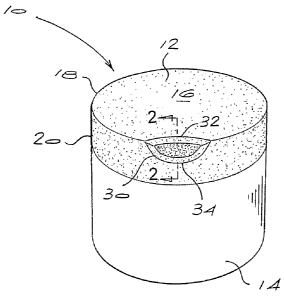
Referring to Figures 1 and 2 of the accompanying drawings, the cutting
element 10 has a polycrystalline diamond layer 12, bonded to a substrate
14. The polycrystalline diamond layer has an upper working surface 16
around which is a peripheral cutting edge 18 and a peripheral surface 20.
The polycrystalline diamond layer 12 has respective regions 22,24 lean in
catalysing material and a region 26 rich in catalysing material. The regions
22,24 lean in catalysing material extend respectively from the working
surface 16 and peripheral surface 20 into the polycrystalline diamond layer
12. The depth of each region, as it extends laterally away from the
respective surface 16,20, will typically be no more than 500 microns, and is


CA 02566597 2006-11-14
WO 2005/110648 PCT/IB2005/001276
-9-
preferably 30 to 400 microns, most preferably 60 to 350 microns. In
addition, the region 24 extends to a depth, from the working surface 16
towards the substrate 14, of at least half the overall thickness of the
polycrystalline diamond layer 12, but preferably stops short of the interface
region 28 by at least 500pm in order to prevent inadvertant leaching of the
interface region 28.

Typically, if the PCD edge is bevelled, the regions 22,24 lean in catalysing
material will generally follow the shape of this bevel and extend along the
length of the bevel. The balance of the polycrystalline diamond layer 12
extending to the cemented carbide substrate 14 is the region 26 rich in
catalysing material. In addition, the surfaces 16,20 of the PCD element may
be mechanically polished so as to achieve a low-friction surface or finish.

In use, as the PCD layer 12 contacts a substrate to be drilled, it develops a
wear scar 30 having a leading edge 32 and a trailing edge 34. By providing
respective regions 22,24 lean in catalysing material, as the wear scar 30
develops both the leading edge 32 and the trailing edge 34 are located in a
region lean in catalysing material. Thus the previously perceived
advantages of removing catalyst material from the working surface of a
PCD abrasive element are now extended to the trailing edge 34, further
improving the performance thereof in use. In the present embodiment, the
region 24 is in the form of a complete annular region lean in catalysing
material. In practise, typically only a few segments of the diamond layer 12
are used in the drilling operation. For instance, the insert may be rotated
through 90 when the wear scar 30 develops too large, thereby forming a
new wear scar. By repeating this operation, four wear scars could develop,
for example. It is therefore possible to leach only those portions of region
24 corresponding to the segments where the respective wear scars will
form, thereby forming a so-called interrupted annular region lean in
catalysing material.

Generally, the layer of polycrystalline diamond 12 will be produced and
bonded to the cemented carbide substrate 14 by methods known in the art.


CA 02566597 2006-11-14
WO 2005/110648 PCT/IB2005/001276
-10-
Thereafter, catalysing material is removed from the working surface 16 and
peripheral surface 20 of the particular embodiment using any one of a
number of known methods. One such method is the use of a hot mineral
acid leach, for example a hot hydrochloric acid leach. Typically, the
temperature of the acid will be about 110 C and the leaching times will be 3
to 60 hours. The area of the polycrystalline diamond layer which is
intended not to be leached and the carbide substrate will be suitably
masked with acid resistant material. This will also apply were an
interrupted region 24 is provided.

In producing the polycrystalline diamond abrasive elements described
above, a layer of diamond particles, optionally mixed with some catalysing
material, will be placed on a cemented carbide substrate. This unbonded
assembly is then subjected to elevated temperature and pressure
conditions to produce polycrystalline diamond of the diamond particles
bonded to the cemented carbide substrate. The conditions and steps
required to achieve this are well known in the art.

The diamond particles will preferably comprise a mix of diamond particles,
differing in average particle sizes. In one embodiment, the mix comprises
particles having five different average particle sizes as follows:

Average Particle Size Percent by mass
(in microns)
20 to 25 (preferably 22) 25 to 30 (preferably 28)
to 15 (preferably 12) 40 to 50 (preferably 44)
5 to 8 (preferably 6) 5 to 10 (preferably 7)
3 to 5 (preferably 4) 15 to 20 (preferably 16)
less than 4 (preferably 2) less than 8 (preferably 5)

In another embodiment, the polycrystalline diamond layer comprises two
layers differing in their mix of particles. The first layer, adjacent the
working
surface, has a mix of particles of the type described above. The second


CA 02566597 2006-11-14
WO 2005/110648 PCT/IB2005/001276
-11-
layer, located between the first layer and the substrate, is one in which (1)
the majority of the particles have an average particle size in the range 10 to
100 microns, and consists of at least three different average particle sizes
and (ii) at least 4 percent by mass of particles have an average particle size
of less than 10 microns. Both the diamond mixes for the first and second
layers may also contain admixed catalyst material.

Representative Drawing
A single figure which represents the drawing illustrating the invention.
Administrative Status

For a clearer understanding of the status of the application/patent presented on this page, the site Disclaimer , as well as the definitions for Patent , Administrative Status , Maintenance Fee  and Payment History  should be consulted.

Administrative Status

Title Date
Forecasted Issue Date 2011-11-08
(86) PCT Filing Date 2005-05-11
(87) PCT Publication Date 2005-11-24
(85) National Entry 2006-11-14
Examination Requested 2010-02-02
(45) Issued 2011-11-08
Deemed Expired 2020-08-31

Abandonment History

There is no abandonment history.

Payment History

Fee Type Anniversary Year Due Date Amount Paid Paid Date
Application Fee $400.00 2006-11-14
Maintenance Fee - Application - New Act 2 2007-05-11 $100.00 2006-11-14
Registration of a document - section 124 $100.00 2007-02-22
Maintenance Fee - Application - New Act 3 2008-05-12 $100.00 2008-03-04
Maintenance Fee - Application - New Act 4 2009-05-11 $100.00 2009-03-16
Request for Examination $800.00 2010-02-02
Maintenance Fee - Application - New Act 5 2010-05-11 $200.00 2010-04-27
Advance an application for a patent out of its routine order $500.00 2010-08-17
Registration of a document - section 124 $100.00 2010-08-18
Maintenance Fee - Application - New Act 6 2011-05-11 $200.00 2011-04-21
Final Fee $300.00 2011-08-22
Maintenance Fee - Patent - New Act 7 2012-05-11 $200.00 2012-04-17
Maintenance Fee - Patent - New Act 8 2013-05-13 $200.00 2013-04-10
Maintenance Fee - Patent - New Act 9 2014-05-12 $200.00 2014-04-09
Maintenance Fee - Patent - New Act 10 2015-05-11 $250.00 2015-04-15
Maintenance Fee - Patent - New Act 11 2016-05-11 $250.00 2016-04-20
Maintenance Fee - Patent - New Act 12 2017-05-11 $250.00 2017-04-19
Maintenance Fee - Patent - New Act 13 2018-05-11 $250.00 2018-04-18
Owners on Record

Note: Records showing the ownership history in alphabetical order.

Current Owners on Record
BAKER HUGHES INCORPORATED
Past Owners on Record
ACHILLES, ROY DERRICK
ELEMENT SIX (PRODUCTION) (PTY) LTD
ELEMENT SIX (PTY) LTD.
Past Owners that do not appear in the "Owners on Record" listing will appear in other documentation within the application.
Documents

To view selected files, please enter reCAPTCHA code :


To view images, click a link in the Document Description column. To download the documents, select one or more checkboxes in the first column and then click the "Download Selected in PDF format (Zip Archive)" or the "Download Selected as Single PDF" button.

List of published and non-published patent-specific documents on the CPD .

If you have any difficulty accessing content, you can call the Client Service Centre at 1-866-997-1936 or send them an e-mail at CIPO Client Service Centre.


Document
Description 
Date
(yyyy-mm-dd) 
Number of pages   Size of Image (KB) 
Cover Page 2011-10-04 2 42
Representative Drawing 2007-01-19 1 8
Cover Page 2007-01-22 1 38
Abstract 2006-11-14 1 60
Claims 2006-11-14 2 57
Drawings 2006-11-14 1 14
Description 2006-11-14 11 463
Description 2011-03-04 14 600
Claims 2011-03-04 13 511
Claims 2011-04-20 13 510
Prosecution-Amendment 2011-04-12 2 36
Correspondence 2007-01-17 1 26
Prosecution-Amendment 2010-09-14 2 36
PCT 2006-11-14 4 155
Assignment 2006-11-14 3 123
Assignment 2007-02-22 2 64
Prosecution-Amendment 2010-02-02 2 70
Correspondence 2011-08-22 2 62
Prosecution-Amendment 2010-08-17 2 75
Prosecution-Amendment 2010-08-26 1 11
Assignment 2010-08-18 15 537
Prosecution-Amendment 2010-09-15 2 81
Prosecution-Amendment 2011-03-04 20 822
Prosecution-Amendment 2011-04-20 4 169