Note: Descriptions are shown in the official language in which they were submitted.
CA 02569101 2012-10-16
100011 MRI BIOPSY APPARATUS INCORPORATING AN IMAGABLE
PENETRATING PORTION
100011 FIELD OF THE INVENTION
100031 The present invention relates, in general, to a method of imaging
assisted tissue
sampling and, more particularly, to an improved method for positioning a
biopsy probe with
respect to a magnetic resonance imaging (MRI) breast coil for acquiring
subcutaneous
biopsies and for removing lesions.
BACKGROUND OF THE INVENTION
100041 Recently, core biopsy devices have been combined with imaging
technology to
better target a lesion in breast tissues. One such commercially available
product is marketed
under the trademark name MAMMOTOMETm, by Ethicon Endo-Surgery, Inc. An
embodiment of such a device is described in U.S. Patent No. 5,526,822 issued
to Burbank, et
al., on June 18,1996. Its handle receives mechanical and electrical power as
well as vacuum
assist from a remotely positioned control module that is spaced away from the
high
magnetic field of a Magnetic Resonance Imaging (MRI) machine.
CA 02569101 2006-11-20
WO 2005/112778 PCT/US2005/017775
2
[0005] As seen from that reference, the instrument is a type of image-
guided,
percutaneous coring, breast biopsy instrument. It is vacuum-assisted, and some
of the
steps for retrieving the tissue samples have been automated. The physician
uses this
device to capture "actively" (using the vacuum) the tissue prior to severing
it from the
body. This allows the sampling of tissues of varying hardness. In addition, a
side
opening aperture is used, avoiding having to thrust into a lesion, which may
tend to push
the mass away, causing a track metastasis, or causing a hematoma that, with
residual
contrast agent circulating therein, may mimic enhancement in a suspicious
lesion. The
side aperture may be rotated about a longitudinal axis of the probe, thereby
allowing
multiple tissue samples without having to otherwise reposition the probe.
These features
allow for substantial sampling of large lesions and complete removal of small
ones.
[0006] In MRI, the presence of both the magnetic and RF fields used in the
imaging
process place several constraints on each instrument to be positioned or
manipulated
near or in the imaging region of the MRI system. The MRI system imposes a
strong
constant magnetic field (e.g, 1 Tesla) to align electrons of the atoms of the
body. Then a
magnetic gradient is applied to disturb these aligned electrons. As the
electrons return to
alignment, a weak RF signal is emitted that must be detected and interpreted.
Compatibility with such an environment requires that the instrument must be
essentially
non-ferromagnetic, so that it is not attracted by the magnetic field and thus
posing, which
would pose a safety problem. This consideration applies to any object that is
used near
(or that is inserted into or implanted within) the patient being imaged,
because the
magnetic field subjects such an object or implants, if ferro-magnetic, to
undesirable
forces and torques. In addition, an electrical instrument should be tolerant
of the static
and pulsed magnetic and RF fields in order to be operable in the presence of
these fields.
Further, an implant or instrument should not be unduly subject to induced
heating due to
eddy current from the applied RF field. Finally, the instrument should not
create
excessive imaging artifacts that obscure or distort the image of the target.
[0007] To address these constraints, MRI compatible biopsy instruments are
generally
assembled from non-ferrous materials; however, other materials that are MRI
imagable.
are sometimes used. In some instances, imagability relies upon the lack of an
MRI RE
return image to contrast with the image returned by adjacent tissue. Also,
ferromagnetic
CA 02569101 2012-10-19
3
particles or liquid lumens for holding aqueous paramagnetic ions. are
sometimes
incorporated.
100081 While these generally-known MRI biopsy devices provide MRI
compatibility and a
degree of imagability, further improvements would be desirable. More
particularly, a
significant need exists for an MRI compatible biopsy device enhances locating
a sampling
aperture in an MR' compatible penetrating portion, even in an MRI scan slice
that
obliquely passes through the probe.
BRIEF SUMMARY OF THE INVENTION
100091 The invention overcomes the above-noted and other deficiencies of
the prior art by
providing an obturator for use with a minimally invasive medical procedure
into human
breast tissue that uses a cannula formed of a magnetic resonance imaging (MRI)
compatible material that has a lateral opening proximate to a distal end and a
longitudinal
lumen sized to receive a core biopsy cutting member. In particular, the
obturator has a
shaft formed of an MRI compatible material that is sized for insertion into
the cannula in
lieu of the core biopsy cutting member. An MRI imagable recess formed in the
obturator
proximate to the lateral opening of the cannula is configured to receive an
MRI visible
material accentuating identification thereof.
10009a1 In an aspect, there is provided an apparatus for use with a
minimally invasive
medical procedure into human breast tissue the apparatus comprising:
a. a cannula formed of a magnetic resonance imaging (MRI)
compatible material, wherein the cannula comprises a lateral
opening proximate to a distal end and a longitudinal lumen sized to
receive a core biopsy cutting member;
CA 02569101 2012-10-19
3a
b. an obturator comprising a shaft formed of an MRI compatible
material and sized for insertion into the cannula in lieu of the core
biopsy cutting member;
c. a recess formed in the obturator proximate to the lateral opening of
the cannula and operably configured to receive an MRI visible
material to enhance local contrast to provide positive identification
of the lateral opening of the cannula; and
d. a plurality of MRI imageable apertures formed in the obturator and
longitudinally spaced proximally from the recess, each MRI
imageable aperture communicating with a lateral surface of the
obturator.
10009b1 In an aspect, there is provided an apparatus for use with a
minimally invasive
medical procedure into human breast tissue, the apparatus comprising:
a. a cannula comprising an open distal end, a lateral opening proximate to
the
open distal end, and a longitudinal lumen communicating with the lateral
opening and the open distal end, the lumen having a non-circular cross-
section; and
b. a obturator sized for insertion into the cannula, obturator having a
distal end
extending from the open distal end of the cannula when the obturator is
inserted fully into the cannula, and the obturator having a recess proximate
of the distal end of the obturator, the recess positioned along a portion of
the
length of the obturator to align with the lateral opening of the cannula when
the obturator is inserted fully into the cannula.
10009c1 In an aspect, there is provided an apparatus for use with a
minimally invasive
medical procedure into human breast tissue, the apparatus comprising:
CA 02569101 2012-10-19
3b
a. a cannula comprising an open distal end, a lateral opening proximate to
the
open distal end, and a longitudinal lumen communicating with the lateral
opening and the open distal end; and
b. an obturator sized for insertion into the cannula, the obturator having
an
open proximal end, a closed distal end, and a lateral recess disposed
proximate of the closed distal end, wherein the closed distal end of the
obturator is configured to extend from the open distal end of the cannula
when the obturator is inserted fully into the cannula, and wherein the lateral
recess of the obturator is disposed on along the length of the obturator such
that the lateral recess aligns with the lateral opening of the cannula when
the
obturator is inserted fully into the cannula; and
wherein the obturator comprises a lumen extending from a proximal end of
the obturator and communicating with the obturator recess.
10009d1 In an aspect, there is provided an apparatus for use with a
minimally invasive
medical procedure into human breast tissue, the apparatus comprising;
a. a hub;
b. a cannula extending distally from the hub, the cannula comprising an
open
distal end, a lateral opening proximate to the open distal end, and a
longitudinal lumen communicating with the lateral opening and the open
distal end; and
c. an obturator sized for insertion through the hub and into the cannula,
the
nonmetallic obturator having a distal end extending from the open distal end
of the cannula when the obturator is inserted fully into the cannula, and the
obturator having a recess proximate of the distal end of the obturator, the
recess positioned along the length of the obturator to align with the lateral
opening of the cannula when the obturator is inserted fully into the cannula;
and
CA 02569101 2012-10-19
,
3c
d. an alignment feature associated with the at least one of the hub and the
obturator for providing alignment of the obturator recess with the lateral
opening of the cannula.
10009e1
In an aspect, there is provided an apparatus for use with a minimally
invasive
medical procedure into human breast tissue, the apparatus comprising:
a. a cannula formed of a magnetic resonance imaging (MRI)
compatible material, wherein the cannula comprises a lateral
opening proximate to a distal end and a longitudinal lumen sized to
receive a core biopsy cutting member;
b. an obturator comprising a shaft formed of an MRI compatible
material and sized for insertion into the cannula in lieu of the core
biopsy cutting member, wherein the obturator comprises a non-
circular cross section; and
c. a recess formed in the obturator proximate to the lateral opening of
the cannula and operably configured to receive an MRI visible
material to enhance local contrast to provide positive identification
of the lateral opening of the cannula.
10009f)
In an aspect, there is provided an apparatus for use with a minimally
invasive
medical procedure into human breast tissue, the apparatus comprising:
a.
a cannula formed of a magnetic resonance imaging (MRI)
compatible material, wherein the cannula comprises a lateral
opening proximate to a distal end and a longitudinal lumen sized to
receive a core biopsy cutting member, wherein the cannula
comprises a proximal end;
CA 02569101 2012-10-19
=
3d
b. an obturator comprising a shaft formed of an MRI compatible
material and sized for insertion into the cannula in lieu of the core
biopsy cutting member, wherein the obturator comprises a proximal
end;
c. a recess formed in the obturator proximate to the lateral opening of
the cannula and operably configured to receive an MRI visible
material to enhance local contrast to provide positive identification
of the lateral opening of the cannula; and
d. a hub coupled to the proximal end of the obturator, wherein the hub
is configured to engage the proximal end of the cannula to align the
lateral opening of the cannula proximate to the recess of the
obturator.
(00101 The present invention shall be made apparent from the accompanying
drawings and
the description thereof
BRIEF DESCRIPTION OF THE FIGURES
1001i The accompanying drawings, which are incorporated in and constitute a
part of this
specification, illustrate embodiments of the invention, and, together with the
general
description of the invention given above, and the detailed description of the
embodiments
given below, serve to explain the principles of the present invention.
100121 FIGURE 1 is a perspective disassembled view of a Magnetic Resonance
Imaging
(MRI) compatible biopsy system incorporating a guided sleeve and obturator,
advantageously MRI compatible and imagable, and providing therapeutic
features;
CA 02569101 2006-11-20
WO 2005/112778 PCT/US2005/017775
4
[0013] FIGURE 2 is a disassembled perspective view of a guidance portion of
a
localization fixture and a disassembled MM biopsy device of the MRI compatible
biopsy
system of FIG. 1;
[0014] FIGURE 3 is a perspective view of the MM biopsy device of FIG. 2,
mounted on
the guidance portion of the localization fixture;
[0015] FIGURE 4 is a perspective disassembled view of an alternative
guidance portion,
including a cradle supporting a sleeve having open distal end and side
aperture, an
imaging obturator with a piercing tip, and a fluid communicating stylet that
is also used to
place a marker for the MM compatible biopsy system of FIG. 1;
[0016] FIGURE 5 is a perspective disassembled view of a further alternative
guidance
assembly supporting a sleeve with an imaging/marking obturator having a fluid
lumen
and piercing tip;
[0017] FIGURE 6 is a right side diagrammatic view in elevation taken in
longitudinal
cross section of the sleeve with an open distal end and lateral aperture and
introducer,
imaging obturator of FIG. 5 with the obturator having a dug-out marker recess;
[0018] FIGURE 7 is a right side diagrammatic view in elevation, taken in
longitudinal
cross section of a sleeve with a side aperture and piercing tip used with an
introducer,
imaging obturator having a dug-out marker recess for the MM compatible biopsy
system
of FIG. 1;
[0019] FIGURE 8 is a right side diagrammatic view in elevation taken in
longitudinal
cross section of a sleeve with a lateral aperture and open distal end used
with an
introducer, imaging obturator having a non-cylindrical cross section and
piercing tip for
the MM compatible biopsy system of FIG. 1;
[0020] FIGURE 9 is a right side diagrammatic view in elevation taken in
longitudinal
cross section of the sleeve of FIG. 7 with an introducer, imaging obturator
having a non-
cylindrical cross section for the MM compatible biopsy system of FIG. 1;
[0021] FIGURE 10 is a right side diagrammatic view in elevation taken in
longitudinal
cross section of a sleeve with an asymmetric piercing tip and lateral aperture
with an
imaging obturator;
CA 02569101 2006-11-20
WO 2005/112778 PCT/US2005/017775
[0022] FIGURE 11 is a front view in transverse cross section of a proximal
portion of the
imaging obturator of FIG. 10 taken along lines 11-11 to expose an X-shaped
cross section
thereof;
[0023] FIGURE 12 is a back view in transverse cross section of a distal
portion of the
imaging obturator of FIG. 10 taken along lines 12-12 depicting the X-shaped
cross
section shaping the prolapse of tissue into the side aperture of the sleeve;
[0024] FIGURE 13 is a front view in transverse cross section of a proximal
portion of an
alternate imaging obturator of FIG. 10, taken along lines 11-11 to expose a
ridged half-
cylinder cross section thereof;
[0025] FIGURE 14 is a back view in transverse cross section of a distal
portion of an
alternate obturator of FIG. 10, taken along lines 12-12 depicting the ridged
half-cylinder
section, shaping the prolapse of tissue into the side aperture of the sleeve;
[0026] FIGURE 15 is a right side view in elevation, taken in longitudinal
cross section of
an alternate imaging obturator, having an asymmetric piercing tip and having a
dug-out
recess capturing an MR1 visible insert;
[0027] FIGURE 16 is a right side view in elevation taken in longitudinal
cross section of
an alternate imaging obturator, having an asymmetric piercing tip and having
an internal,
proximally communicating cavity holding a distally positioned MRI visible
insert;
[0028] FIGURE 17 is a right side view in elevation taken in longitudinal
cross section of
an alternate imaging obturator, having an internal, proximally communicating
cavity
configured to draw body fluid into a dug-out recess;
[0029] FIGURE 18 is a right side view in elevation taken in longitudinal
cross section of
the alternate imagingmarker obturator of FIG. 17 after drawing tissue into the
side
aperture of the sleeve to present an MRI visible contour;
[0030] FIGURE 19 is a right side view in elevation, taken in longitudinal
cross section of
the alternate imagingmarker obturator of FIG. 17 with an MRI visible material
contained
within a sheath-covered lateral notch;
CA 02569101 2006-11-20
WO 2005/112778
PCT/US2005/017775
6
[0031] FIGURE 20 is a right side view in elevation taken in longitudinal
cross section of
an assembled imagingmarker obturator, including a solid stylet having a
lateral notch and
encompassed by a penetrating sheath with a molded, asymmetric piercing tip;
[0032] FIGURE 21 is a right side view in elevation, taken in longitudinal
cross section of
an obturator, having an open distal end and a lateral aperture with vacuum
assisted air
evacuation to allow a marker lumen to fill with bodily fluids to present an
MRI visible
material;
[0033] FIGURE 22 is a right side view in elevation, taken in longitudinal
cross section of
an obturator having a piercing distal end and a lateral aperture with vacuum
assisted air
evacuation to allow a marker lumen to fill with bodily fluids to present an
MRI visible
material;
[0034] FIGURE 23 is a right side view in elevation, taken in longitudinal
cross section of
an obturator having a closed, blunt distal end and a marker lumen containing
an MRI
visible material (e.g., gadolinium solution, aqueous solution) having an MRI
dark plug
(e.g., collagen, nonferrous metal, plastic) positioned and containing fluid
passages to
correspond to a side aperture of a sleeve;
[0035] FIGURE 24 is a right side view in elevation, taken in longitudinal
cross section of
an obturator having a piercing distal end and a marker lumen containing an MRI
visible
material (e.g., gadolinium solution, aqueous solution) having an MRI dark plug
(e.g.,
collagen, nonferrous metal, plastic) positioned and containing fluid leak
passages to
correspond to a side aperture of a sleeve;
[0036] FIGURE 25 is a right side view in elevation, taken in longitudinal
cross section of
an obturator having a piercing distal end and a marker lumen containing an MRI
visible
material (e.g., gadolinium solution, aqueous solution) having an MRI dark plug
(e.g.,
collagen, nonferrous metal, plastic) positioned and containing fluid passages
to
communicate with an obturator side aperture;
[0037] FIGURE 26 is a side view in elevation of a sleeve having a notch and
an open
distal end with an imaging obturator shown in phantom for the MRI compatible
biopsy
system of FIG. 1.
CA 02569101 2006-11-20
WO 2005/112778
PCT/US2005/017775
7
[0038] FIGURE 27 is a cross section view, taken along lines 27-27
perpendicular to a
longitudinal axis of the sleeve of FIG. 26;
[0039] FIGURE 28 is a side view in elevation of the obturator of FIG. 26
with an upper
portion, which slidingly engages longitudinally a bottom portion along a
dovetail joint,
proximally drawn for exposing a notch in the sleeve;
[0040] FIGURE 29 is a cross section view, taken along lines 29-29
perpendicular to a
longitudinal axis of the obturator of FIG. 28 showing an oval-shaped sleeve
lumen;
[0041] FIGURE 30 is a side view in elevation of a sleeve with an integral
sharp attached
to a shaft having a circular cutter lumen and an underlying vacuum lumen;
[0042] FIGURE 31 is a cross section view taken along line 31-31
perpendicular to a
longitudinal axis of the sleeve of FIG. 30 showing a circular cutter lumen and
underlying
vacuum lumen;
[0043] FIGURE 32 is a side view in elevation of the sleeve of FIG. 31, cut
away to
expose a rotatable obturator that selectively closes a notch in the sleeve;
[0044] FIGURE 33 is a cross section view taken along line 33-33
perpendicular to a
longitudinal axis of the sleeve of FIG. 32;
[0045] FIGURE 34 is a depiction of an MRI display with the selected imaging
slice
passing substantially along the longitudinal length of a coaxial sleeve and
obturator of
FIG. 28 with the obturator in its closed position to block the notch of the
sleeve;
[0046] FIGURE 35 is a depiction of an MRI display with the selected imaging
slice
passing perpendicularly through the longitudinal length of the coaxial sleeve
and
obturator of FIG. 34, taken along lines 35-35;
[0047] FIGURE 36 is a depiction of an MRI display with the selected imaging
slice
passing substantially along the longitudinal length of a coaxial sleeve and
obturator of
FIG. 28 with the obturator in its open position to open the notch of the
sleeve;
[0048] FIGURE 37 is a depiction of an MRI display with the selected imaging
slice
passing perpendicularly through the longitudinal length of the coaxial sleeve
and
obturator of FIG. 36, taken along lines 37-37;
CA 02569101 2006-11-20
WO 2005/112778 PCT/US2005/017775
8
[0049] FIGURE 38 is a right side view in elevation, taken in longitudinal
cross section of
a distal portion of an obturator having a lateral notch accentuated by an MRI
visible
marker and communicating with a marker deployment lumen;
[0050] FIGURE 39 is a right side view in elevation, taken in longitudinal
cross section of
a distal portion of an obturator having a lateral notch accentuated by
flanking marker
bands and communicating with an underlying vacuum lumen;
[0051] FIGURE 40 is a right side view in elevation, taken in longitudinal
cross section of
an obturator with a side notch with a deployment ramp and marker / tool lumen;
[0052] FIGURE 41 is a right side view in elevation, taken in longitudinal
cross section of
a core needle having an annular ring MRI visible marker about an open distal
end that
communicates with a longitudinal marker / tool lumen;
[0053] FIGURE 42 is a diagrammatic view of a process to produce polymide
for an MRI
biopsy device;
[0054] FIGURES 43A-43D are cross sectional views of a round, oval,
square/rectangular,
and complex -shaped sleeve;
[0055] FIGURE 44A is a front view of a perform sleeve placed within a
compression
fixture;
[0056] FIGURE 44B is a front view of the sleeve of FIG. 44A after lateral
compression
to form an oval cross sectional shape;
[0057] FIGURE 44C is a front view of the oval sleeve of FIG. 44B after
heating to form a
cohesive permanent shape;
[0058] FIGURE 45A is a front view of a perform round sleeve positioned in a
forming
fixture of a waisted oval mandrel inserted through the sleeve and the sleeve
placed
between compression plates having opposing pinching portions;
[0059] FIGURE 45B is a front view of the perform round sleeve after
compression and
heating of the forming fixture of the compression plates against the mandrel
with the
perform sleeve trapped therebetween to acquire a waisted oval shape;
CA 02569101 2006-11-20
WO 2005/112778
PCT/US2005/017775
9
[0060] FIGURE 45C is a front view of the waisted oval sleeve after release
from the
forming fixture of FIG. 45B;
[0061] FIGURE 45D is a front view of a forming fixture with compression
plates and
mandrel shaped to constrain the perform sleeve for compression and heating in
a full
circumference to form a waisted oval shape;
[0062] FIGURE 45E is a front view of the waisted oval shaped sleeve after
release from
the forming fixture of FIG. 45D;
[0063] FIGURE 46 is a perspective view of a sleeve with laser formed
proximal
mounting holes for overmolding and side aperture;
[0064] FIGURE 47A is a right side view in elevation through a longitudinal
cross section
of a proximal portion of a sleeve having laser formed through holes over
molded with a
sleeve hub;
[0065] FIGURE 47B is a right side view in elevation through a longitudinal
cross section
of a proximal portion of a sleeve having a laser formed relieved area over
molded to form
a sleeve hub;
[0066] FIGURE 48 is a top diagrammatic view of a dual point flat blade
attached in a slot
in a conic distal piercing tip of an obturator or sleeve;
[0067] FIGURE 49A is a top diagrammatic view of a primary/secondary conic
piercing
tip of an obturator or sleeve;
[0068] FIGURE 49B is a front view in elevation of the primary/secondary
conic piercing
tip of FIG. 49A;
[0069] FIGURE 50 is a geometric diagram of insertion torques for positive
angles for the
piercing tip of FIGS. 49A-49B;
[0070] FIGURE 51 is a geometric diagram of insertion torques for negative
angles for the
piercing tip of FIGS. 49A-49B;
[0071] FIGURE 52A is a perspective view of an alternate flat, triangular
cutting member
for a piercing portion of a sleeve or obturator;
CA 02569101 2006-11-20
WO 2005/112778
PCT/US2005/017775
[0072] FIGURE 52B is a top view of the alternate flat, triangular cutting
member of FIG.
52A;
[0073] FIGURE 53 is a left side view in elevation of an obturator with flat
bladed
piercing tip, lumen communicating between a lateral notch and fluid fitting on
a proximal
end with external engaging features for an obturator hub;
[0074] FIGURE 54 is a front view in elevation of the obturator of FIG. 53;
[0075] FIGURE 55 is a left side, view in elevation of a longitudinal cross
section of the
obturator of FIG. 54 taken along lines 55-55;
[0076] FIGURE 56 is a front view in elevation of the obturator of FIG. 53
taken in cross
section along lines 56-56 distal to a hub engaging portion;
[0077] FIGURE 57 is a front view in elevation of the obturator of FIG. 53
taken in cross
section along lines 57-57 across the hub engaging portion;
[0078] FIGURE 58 is a left side view in elevation of an obturator with a
flat piercing tip,
lumen communicating between a lateral notch and a proximal end and a
longitudinally
spaced vertical imaging wells of incrementatally varied diameters;
[0079] FIGURE 59 is a top view of the obturator of FIG. 58;
[0080] FIGURE 60 is an aft view of the obturator of FIG. 58 taken in cross
section along
lines 60-60 showing the piercing tip in phantom;
[0081] FIGURE 61 is a left side view in elevation of an obturator with flat
bladed
piercing tip, lumen communicating between a lateral notch and a proximal end,
and slat
imaging cavities of incremented cross sectional area;
[0082] FIGURE 62 is a top view of the obturator of FIG. 61;
[0083] FIGURE 63 is an aft view in elevation of the obturator of FIG. 61
taken in cross
section along lines 63-63 through a lateral notch showing the piercing tip in
phantom;
[0084] FIGURE 64 is a front view in elevation of the obturator of FIG. 61
taken in cross
section along lines 64-64 through a slat imaging cavity;
CA 02569101 2006-11-20
WO 2005/112778
PCT/US2005/017775
11
[0085] FIGURE 65 is a left side view in elevation of an obturator with a
flat piercing tip,
lumen communicating between a lateral notch and a proximal end, and an
alternative
series of slat imaging cavities;
[0086] FIGURE 66 is a top view of the obturator of FIG. 65;
[0087] FIGURE 67 is an aft view of the obturator of FIG. 65 taken in cross
section
through the lateral notch and showing the piercing tip in phantom;
[0088] FIGURE 68 is a front view in elevation of the obturator of FIG. 65
taken in cross
section through lines 68-68;
=
[0089] FIGURE 69 is an MRI image of a left side of an obturator having a
lateral notch
with 30 degree corners;
[0090] FIGURE 70 is an MRI image of a left side of an obturator having a
lateral notch
with 60 degree corners;
[0091] FIGURE 71 is an MRI image of a left side of an obturator having a
lateral notch
with canoe dugout;
[0092] FIGURE 72 is an MRI image of a left side of the obturator of FIG.
53;
[0093] FIGURE 73 is an MRI image of a left side of the obturator of FIG. 53
with a
lumen containing a soaked collagen plug;
[0094] FIGURE 74 is an MRI image of a left side of the obturator of FIG. 58
filled with
an aqueous gel; and
[0095] FIGURE 75 is an MRI image of a left side of the obturator of FIG. 61
filled with
gadolinium.
DETAILED DESCRIPTION OF THE INVENTION
[0096] Turning to the Drawings, wherein like numerals denote like
components
throughout the several views, in FIG. 1, a Magnetic Resonance Imaging (MRI)
compatible biopsy system 10 includes a guide that guides a sleeve and
introducer
obturator that are separate from the biopsy device itself and advantageously
incorporate
an improved piercing portion, MRI imaging marker, and fluid handling
capabilities.
CA 02569101 2006-11-20
WO 2005/112778
PCT/US2005/017775
12
Mounting provisions allow for precise penetration along a desired trajectory
without
overshooting.
[0097] The MRI compatible biopsy system 10 includes a control module 12
that typically
is placed outside of a shielded room containing an MRI machine (not shown) or
at least
spaced away to mitigate detrimental interaction with its strong magnetic field
and/or
sensitive radio frequency (RF) signal detection antennas. The control module
12 controls
and powers an MRI biopsy device 14 that is compatible for use in close
proximity to the
MRI machine. An example of an MRI biopsy device 14 is the afore-mentioned
MAMMOTOMETm instrument. The MRI biopsy device 14 is accurately positioned by a
localization fixture 16 that is attached to a breast coil 18, which in turn
supports a patient
(not shown). Examples of commercially available breast coils 18 include the
BIOPSY
BREAST COIL MODEL BBC by MRI DEVICES CORPORATION of Waukesha WI. A
guidance assembly 20, and, in particular, a sleeve 22, advantageously attaches
to the
localization fixture 16 to increase imaging and therapeutic flexibility and
accuracy in
conjunction with selective use of the MRI biopsy device 14 during particular
parts of the
procedure. The guidance assembly 20 may include one or more obturators 24 with
one
depicted that seals the sleeve 22 during insertion and during subsequent
portions of the
procedure in which the MRI biopsy device 14 is not inserted therein. A depth
stop 26 is
provided for use with the localization fixture 16 to advantageously prevent
over-insertion
of the sleeve 22, inadvertent retraction of the sleeve 22 and/or to enhance
accurate
placement of the sleeve 22 to at a desired location along the Z-Axis.
[0098] For convenience, herein a convention is used for locating a
suspicious lesion by
Cartesian coordinates within breast tissue referenced to the localization
fixture 16 and to
thereafter position an instrument (e.g., sleeve 22) to this location without
necessarily
continuously imaging the region. As will be described in greater detail below,
a
perforated barrier that is compressed along an outside side of the breast,
with respect to a
medial plane of the chest of the patient, defines an X-Y plane, with the X-
axis being
vertical (sagittal) with respect to a standing patient and which corresponds
to a left to
right axis as viewed by a clinician facing the externally exposed portion of
the
localization fixture 16. A fiduciary marker (not shown)), attached to or
positioned relative
to the localization fixture 16 proximate to the patient's skin, defines the
origin of this
plane. Perpendicular to this X-Y plane and extending toward the medial side of
the breast
CA 02569101 2006-11-20
WO 2005/112778
PCT/US2005/017775
13
is the Z-axis, which typically corresponds to the orientation and depth of
insertion of the
MRI biopsy device 14, although it should be appreciated that variations may
allow
insertion at an angle to this Z-axis. Thus, for clarity, the term Z-axis may
be used
interchangeably with "axis of penetration", although the latter may or may not
be
orthogonal to the spatial coordinates used to locate an insertion point on the
patient.
[0099] Separating the tracking rail, that supports a mount / depth stop
from a biopsy rail
that supports the weight of the biopsy device, advantageously reduces
interference
between the various components, allowing a sequence of operation wherein
certain
components may be selectively installed and removed without interfering with
other
components.
[00100] In use, the MRI compatible biopsy system 10 is prepared for use by
placing a
cable management spool 30 upon a cable management attachment saddle 32 that
projects
from a side of the control module 12. Wound upon the cable management spool 30
is a
paired electrical cable 34 and mechanical cable 36 for communicating control
signals and
cutter rotation/advancement motions respectively. In particular, electrical
and mechanical
cables 34, 36 each have one end connected to respective electrical and
mechanical ports
40, 42 in the control module 12 and another end connected to a holster 44 that
receives
the MRI biopsy device 14. An MRI docking cup 46, which may hold the holster 44
when
not in use, is hooked to the control module 12 by a docking station mounting
bracket 48.
[00101] An interface lock box 50, mounted to a wall, provides a tether 52
to a lockout port
54 on the control module 12. The tether 52 is advantageously, uniquely
terminated and of
short length to preclude inadvertent positioning of the control module 12 too
close to the
MRI machine. An in-line enclosure 56 may advantageously register the tether
52,
electrical cable 34 and mechanical cable 36 to their respective ports 54, 42,
44 on the
control module 12. A remote keypad 58 may be distally connected to the
electrical cable
34 to enhance clinician control of the MRI biopsy device 14, especially when
controls on
the MR1 biopsy device 14 itself are not readily accessible after insertion
into the
localization fixture 16.
[00102] Vacuum assist is provided by a first vacuum line 60 that connects
between the
control module 12 and an outlet port 62 of a vacuum canister 64 that catches
liquid and
solid debris. A tubing kit 66 completes the pneumatic communication between
the control
CA 02569101 2006-11-20
WO 2005/112778 PCT/US2005/017775
14
module 12 and the MRI biopsy device 14. In particular, a second vacuum line 68
is
connected to an inlet port 70 of the vacuum canister 64. The second vacuum
line 68
divides into two vacuum lines 72, 74 that are attached to the MRI biopsy
device 14. With
the MRI biopsy device 14 installed in the holster 44, the control module 12
performs a
functional check. Saline is manually injected into biopsy device 14 to serve
as a lubricant
and to assist in achieving a vacuum seal. The control module 12 actuates a
cutter
mechanism (not shown) in the MRI biopsy device 14, monitoring full travel.
[00103] The portion of the MRI compatible biopsy system 10 used near the
MRI machine
is also assembled. The generally known breast coil 18 is placed upon a gantry
of the MRI
machine, along with other body support' pads (not shown). The localization
fixture 16,
which is attached within a recess on either lateral side of the breast coil 18
to access a
patient's breast that is pendulously exposed therein, includes a horizontal
medial plate 80,
a reusable base assembly 82, a lateral assembly 84, and a positioning pedestal
86. The
localization fixture 16 is also assernbled with a disposable medial fence 90
and a lateral
window (or perforated plate) 92.
[00104] The base assembly 82 is placed within a selected lateral recess of
the breast coil
18. The medial fence 90 attaches to a medial edge of the medial plate 80,
aligned
vertically approximately along a longitudinal axis of the breast coil 18 under
an inner
edge of a selected breast aperture 94 that receives a patient's breast. With
the patient thus
positioned and the outer area of the breast sterilized, the lateral window 92
is downwardly
slid into a three-sided frame guide 96 of the lateral assembly 84, which in
turn is placed
upon the medical plate 80. The base assembly 82 and lateral assembly 84 are
moved with
respect to one another along the Z-axis to compress the patient's breast
between the
medial fence 90 and the lateral window 92. A mechanism formed between the
lateral
assembly 84, base assembly 82, and medial plate 80 maintains this compression.
[00105] Contrast agent may be injected into the patient to enhance the
imaging. The gantry
is advanced into the MRI machine bore to image the localization fixture 16 and
breast
tissue. The fiduciary marker on the lateral window 92 is located and
designated as the
origin of the X-Y-Z coordinates. Then a suspicious lesion is located within
the image and
a point thereon selected to determine its location relative to the origin. It
should be
appreciated that orienting the X-Y-Z axis of an initial scan may be
facilitated by having
CA 02569101 2006-11-20
WO 2005/112778
PCT/US2005/017775
the lateral window 92 formed of an imagable material, thus presenting an X-Y
plane in
addition to the origin point of the fiduciary marker. With the target location
determined,
the gantry is withdrawn from the MRI machine bore.
[00106] The positioning pedestal 86 is slidably engaged along the X-axis of
the lateral
assembly 84 and defines a vertical guide for positioning a single targeting
rail ("track")
98 at a selected Y-axis coordinate. The track 98 in turn provides a depth
guide along the
Z-axis for positioning the depth stop 26 and the holster 44 at a desired Z-
axis coordinate.
The depth stop 26 is latched onto the track 98. Thereafter, a marking
instrument (not
shown) may be inserted through the depth stop 26 to mark the insertion point
on the
breast. Thereafter, the depth stop 26 is moved out of the way. Anesthesia is
injected
superficially, followed by a scoring cut at the marked location and a
subsequent injection
of anesthesia more deeply into the scored cut. The depth stop 26 is then
repositioned on
the track 98 to the desired Z-axis coordinate reference.
[00107] The obturator 24 is inserted into the sleeve 22 and may be
positioned to close any
apertures of the sleeve 22 (side and/or distal end) to present a closed
surface to the breast
tissue. The obturator may also be shaped or formed to-enhance the visibility
of the
aperture location. One or the other of the obturator 24 and sleeve 22 presents
a sharp tip
(not shown) to penetrate breast tissue. For instance, if using a sleeve 22
having an open
end, an obturator may provide a sharp tip.
[00108] The obturator 24 is inserted into the sleeve 22 and the combination
is guided by
the track 98 to a proper orientation until an accurate depth is reached as set
by the depth
stop 26. Once fully inserted, the depth stop 26 prevents over-insertion. The
sleeve 22
advantageously latches to the track 98 and/or the depth stop 26 to prevent
inadvertent
retraction, such as when the obturator 24 is withdrawn, and pressure is
received from the
breast tissue or later when a probe 100 of the MRI biopsy device 14 is
withdrawn from
the sleeve 22.
[00109] The gantry is moved into the MRI machine bore and the patient is
imaged again to
confirm placement of the sleeve 22 with respect to the suspicious lesion.
Advantageously,
imagable materials of the sleeve 22 and/or obturator 24, perhaps comprising or
including
marker material, enhance the ability to confirm the location of the sleeve 22
and its sleeve
side aperture 102 as positioned for subsequent biopsy samples.
CA 02569101 2006-11-20
WO 2005/112778
PCT/US2005/017775
16
[00110] The patient is removed from the MRI machine by retracting the
gantry and the
holstered MRI biopsy device 14 is brought to the localization fixture 16. A
protective cap
(not shown) is removed from the probe 100 of the MRI biopsy device 14 and the
obturator 24 is removed from the sleeve 22. Mounting of the holster 44 to the
track 98 is
shown in FIGS. 2 and 3, wherein the holster 44 and MRI biopsy device 14
combination
slide onto the track 98 that has been positioned at a certain location with
respect to the
pedestal 86 and lateral assembly 84. Features of the sleeve 22 and probe 100
may
advantageously visually and mechanically orient a probe side aperture 104 of
the probe
100 with the sleeve side aperture 102, as well as forming a gas seal.
Advantageously, the
holster 44 and/or the probe 100 may latch onto the track 98 or sleeve 22 to
confirm full
insertion and prevent over-insertion and inadvertent retraction. The holster
44 allows an
MRI biopsy device 14, intended for handheld use, to have sufficient support in
its
attachment to the localization fixture 16 to accurately maintain its position
and to avoid or
minimize loads carried by the probe 100.
[00111] Thereafter, the MRI compatible biopsy system 10 may take tissue
samples by
activating a cutter mechanism in conjunction with vacuum assist, withdrawing
the cutter
and withdrawing a tissue sample, the latter perhaps also with vacuum assist.
The probe
100 / sleeve 22 combination is capable of manual, or perhaps automatic,
rotation to a
desired angle with respect to their longitudinal axis for additional samples
or additional
samples may be taken at the current orientation by further resorting to vacuum
assist. The
cutter is then advanced to close the probe side aperture 104 and the holster
44 is
withdrawn from the localization fixture 16, thereby removing the probe 100
from the
sleeve 22.
[00112] Additional steps or combinations of steps may be performed at this
point, such as
using the probe 100, a specialized obturator 24 (e.g., stylet), or merely the
sleeve 22 to
guide various agents to the surgical site of the biopsy. Examples include
draining fluids,
inserting anesthetic agents, inserting hemostatic agents, insuffiating with
pneumatic
pressure and inserting a marker for subsequently locating the site of the
biopsy, or other
diagnostic or therapeutic procedures.
[00113] The patient is then typically drawn back into the MRI machine bore
for reimaging
to confirm removal of at least a portion of the suspicious lesion and possibly
placement of
CA 02569101 2006-11-20
WO 2005/112778 PCT/US2005/017775
17
a marker. During this reimaging, the sleeve 22 is sealed with the obturator or
stylet 24.
Thereafter, the localization fixture 16 is removed, the patient is bandaged
and removed
from the gantry, and the disposable portions of the MRI compatible biopsy
system 10 are
disposed of as medical waste.
[00114] With particular reference to FIGS. 2-3, the single targeting rail
98 facilitates
sequential mounting of separate components. First, the depth stop 26, then the
sleeve 22
(as in FIG. 1), and then the biopsy tool 14 is slid onto the single targeting
rail 98.
Alternatively as depicted in FIGS. 2-3, the single targeting rail 98 may
receive the depth
stop 26 and then an MRI biopsy device 14 is used without a separate sleeve 22.
The
maximum depth of penetration into the patient's breast is preset by the
location of the
depth stop 26 on the single targeting rail 98. An engagement mechanism between
the
holster 44 and the single targeting rail 98 (not shown) and/or an engagement
mechanism
formed by a catch, depicted as an upwardly projecting pin 110, on an upper
rail-gripping
arm 112 of the depth stop 26 and a downwardly spring-biased rocker latch 114
that snaps
onto the upwardly projecting pin 110, preventing inadvertent retraction of the
MRI biopsy
device 14. The holster 44 may be disengaged by downward pressure on a proximal
actuating arm 116 of the rocker latch 114.
[00115] The single targeting rail 98 may be longitudinally sized to extend
proximally
ufficiently so that the MRI biopsy device 14 engages the single targeting rail
98 prior to
the probe 100 contacting the patient's skin. The single targeting rail 98 is
also sized to not
extend proximally to the extent that it would preclude use in a closed bore
MRI machine
(not shown). Such an MRI compatible biopsy system 10 is believed to minimize
the
procedure turn-around time to less than 45 minutes as described above.
However, despite
the expeditious turn-around, a radiologist may position the probe 100
accurately to within
2 mm (5 mm maximum) of the lesion center. Further, the radiologist may
maximize
access to both breasts (left or right) during a procedure (both sides of the
table) with
minimal repositioning of the patient. Further, a minimal amount of force is
needed to
penetrate tissue, such as less than 4 lbs. Although the depth stop 26 serves
to prevent
overshooting, features for repositioning the depth stop 26 prior to further
insertion of the
probe 100 allow clinical flexibility in targeting another location.
CA 02569101 2006-11-20
WO 2005/112778 PCT/US2005/017775
18
[00116] In FIG. 4, an alternative guidance assembly 200 for the MRI
compatible biopsy
system 10 incorporates a cradle 202 that attaches to a targeting rail 204 and
provides a
biopsy rail 206 for supporting the MRI biopsy device, both rails 204, 206
aligned to the Z
axis. The targeting rail 204 is attached to the positioning pillar 86 (not
shown in FIG. 4)
and is vertically adjusted to a desired Y-position. A circular attachment
point 208 may
form a rotational engagement to the positional pedestal 86 to allow an angled
targeting
guide.
[00117] A lateral face 210 of the targeting rail 204 includes an upper
flange 212 and a
lower flange 214, each having ant-shaped cross section for slidingly receiving
a sleeve
mount 216. Vertical rows of laterally projecting ridges 218 in each flange
212, 214 serve
as a locking surface for the sleeve mount 216. Between the flanges 212, 214, a
side
channel 220 is recessed therein. The sleeve mount 216 guides a sleeve 222 by
having its
sleeve hub 224 proximally received in a hub receptacle 225 of the sleeve mount
216 and
is distally positioned and constrained by a depth stop 226.
[00118] The depth stop 226 includes a slide member 228 that engages the
side channel
220. A depth stop housing 230 attaches thereto, terminating in a reticule 232.
A locking
lever 234 is vertically pinned within a distally open recess (not shown),
defined in the
depth stop 226 with a lateral portion 236 spring biased away therefrom such
that distally
projecting feet 238 pivot against and engage the ridges 218, especially
against a proximal
movement. Depressing the lateral portion 236 proximally against the distally
open recess
of the depth stop housing 230 releases the distally projecting feet 238 to
allow
repositioning the depth stop 226 distally.
[00119] An axis of penetration of the biopsy device 10 is aligned with the
axes defined by
the targeting rail 204 and the biopsy rail 206, which are laterally and
vertically
orthogonally offset therefrom, respectively. Extending a horizontal plane from
the
targeting rail 204 and extending a vertical plane from the biopsy rail 206
intersect at a
common centerline that is the axis of penetration. Having the biopsy rail 206
vertically
aligned and parallel to the axis of penetration advantageously provides
support for the
weight of the biopsy device 14 with a minimum of torsion loads that may
otherwise
create deflections of an inserted distal end. Thereby, even for a relatively
heavy and
elongated device, positioning and maintaining its distal end is achievable
within 5 mm,
CA 02569101 2006-11-20
WO 2005/112778 PCT/US2005/017775
19
and even 2 mm, of a desired insertion point. Thereby, a "hands free" procedure
may be
performed, avoiding the inconvenience or the impracticability of penetration
in the
illustrative version may be replaced by one vertically displaced above the
axis of
penetration. In particular, having a cradle that may be engaged to either side
of the
targeting rail 204 would provide further vertical symmetry and would allow the
operator
to take full advantage of the space afforded by the breast coil 18.
[00120] While a "hands free" capability is advantageous for a single
insertion / multiple
sample biopsy device, it should be appreciated that such penetration guidance
with a
preset depth stop as described herein has application to even light-weight
biopsy devices
that employ a core needle biopsy with a single insertion per single sample. In
particular,
correct placement need not be conditional on continuous imaging. Over
penetration
during insertion and inadvertent displacement is avoided when hands are free.
[00121] A bottom dovetail channel 240 in the targeting rail 204 receives a
top dovetail
extension 242 on the cradle 202, which is slid therein. It should be
appreciated that
mounting is shown herein on the right side of the positioning pedestal 86 when
viewed
proximally, but that the guidance assembly 200 advantageously comprises
symmetric
parts that allow mounting and use on either side of the positioning pedestal
86 to increase
flexibility in positioning the probe 100. Thus, a horizontal base 244 of the
cradle 202
forms the biopsy rail 206 as a biopsy guide channel 246 flanked by a first and
second pair
of monocle receptacles 248, 250 so that a pair of locking hooks 252 on a
monocle 254
may be inserted in either pair of monocle receptacles 248, 250, depending on
which is
closer to the patient. Rather than mounting the cradle 202 to the targeting
rail 204 as
depicted, the cradle may be directly attached to the positioning pedestal 86
(not shown).
The cradle 202 is mechanically robust and can support the gross weight of the
MRI
biopsy device 14. Since the MRI biopsy device 14 does not share the cradle
202, the
cradle 202 may be optimized to support the MRI biopsy device 14 when either
shallow or
deep lesions need to be accessed.
[00122] A guide bushing 256 inserted in a monocle reticule 258 guides a
marking
instrument and/or a scoring scalpel (not shown) as an initial step in locating
and preparing
an insertion point. The monocle 254 may be removed thereafter or left in place
to guide
the sleeve 222 in addition to the reticule 232 of the depth stop 226, the
latter which may
CA 02569101 2006-11-20
WO 2005/112778 PCT/US2005/017775
also hold a guide bushing 260 for guiding the sleeve 222. Removing the guide
bushings
256, 260 allows for the reticules 258, 232 of the monocle 254 and depth stop
226 to guide
a larger component, such as a fiducial 262 used for locating a suspicious
lesion relative to
the guidance assembly 200.
[00123] The alignment of the sleeve 222 is maintained by first passing
through the hub
receptacle 225 of the sleeve mount 216, which receives the sleeve hub 224. In
the
illustrative version, the sleeve 222 has an open ended shaft 266 for receiving
an
introducer obturator 268 that includes a piercing tip (e.g., flat blade) 270
at a distal end of
solid obturator shaft 272. A beveled recess 276 into the solid obturator shaft
272 is
aligned with a sleeve side aperture 278 of the sleeve 222, and thus ultimately
of the probe
100 (FIGS. 1-3). The materials of the obturator 268 may be selected to aid in
locating the
sleeve side aperture 276 of the sleeve 222, which otherwise may be more
difficult to
visualize and locate in an MRI scan slice.
[00124] The sleeve hub 224 has its proximal cylindrical edge 280 attached
to a guidance
thumbwheel 282 that proximally extends from the hub receptacle 225 of the
sleeve mount
216 for rotating the sleeve 222 to position its sleeve side aperture 278 with
reference to a
visual mark, depicted as a locking slot 284, on the thumbwheel 282
corresponding
thereto. The thumbwheel 282 includes a central through hole 286 sealed by a
wiper seal
288 and a duckbill seal 290 trapped between the thumbwheel 282 and the
proximal
cylindrical edge 280iof the sleeve hub 224. Thus, insertion of the obturator
268, which
includes a locking tab 292 that enters the locking slot 284, closes the
central through hole
286 and forms a dynamic seal against the wiper seal 288.
[00125] After removing the obturator 268, a stylet 298 may be inserted into
the sleeve 222
so that a proximally presented hose nib 300 of the stylet 298 may be used to
insufflate the
surgical site or used for other purposes such as draining bodily fluids or
inserting
therapeutic or diagnostic agents through a stylet shaft 302 of the stylet 298
to a stylet side
aperture 304 that is aligned with the side aperture 278 of the sleeve 222. The
stylet 298
also includes a locking tab 306.
[00126] The sleeve mount 216 includes a downwardly spring-biased rocker
latch 308 that
snaps onto a ramped catch 310 on the depth stop 226, preventing inadvertent
retraction of
the sleeve 222. The sleeve mount 216 may be disengaged by downward pressure on
a
CA 02569101 2006-11-20
WO 2005/112778 PCT/US2005/017775
21
proximal actuating arm 312 of the rocker latch 308. An upwardly spring-based
rocker
latch 314, attached to the bottom of the sleeve mount 216, similarly engages
the depth
stop 226. Thus, after the depth stop 226 is set on the targeting rail 204 to a
desired depth
of insertion, the sleeve mount 216 may be distally advanced without
overshooting and
subsequently may be held in place when removing implements therefrom such as
the
obturator 268, stylet 298, and MRI biopsy device 14.
[00127] In FIG. 5, a further alternative guidance assembly 400 for the MRI
compatible
biopsy system 10 includes a cradle 402 that engages a bottom channel 403 of a
primary
targeting rail 404. To provide additional guidance to the MRI biopsy device 14
of FIGS.
1-3, a secondary targeting rail 406 includes a lateral channel 408 that is
guided along a
longitudinal guide tab 410 of the primary targeting rail 404. When fully
engaged thereon,
a pawl 412, pivoting under urging of a pawl spring 414 about a vertical pawl
pin 416 in a
lateral window 418 proximally positioned in the secondary targeting rail 406,
drops into a
proximal detent 420 proximally positioned on the primary targeting rail 404.
[00128] A sleeve 422 includes a hollow shaft (or cannula) 423 that is
proximally attached
to a cylindrical hub 424 and has a lateral aperture 426 proximate to an open
distal end
428. The cylindrical hub 424 has an exteriorly presented thumbwheel 430 for
rotating the
lateral aperture 426. The cylindrical hub 424 has an interior recess 432 that
encompasses
a duckbill seal 434, wiper seal 436 and a seal retainer 438 to provide a fluid
seal when the
shaft 423 is empty and to seal to an inserted introducer obturator 440.
[00129] The introducer 440 advantageously incorporates a number of
components with
corresponding features. A hollow shaft 442 includes a fluid lumen 444 that
communicates
between a side opening 446 and a proximal port 448. The hollow shaft 442 is
longitudinally sized to extend a piercing tip 449, when fully engaged, out of
the distal end
428 of the sleeve 422. An obturator thumbwheel cap 450 encompasses the
proximal port
448 and includes a locking feature 452, which includes a visible angle
indicator 454, that
engages the sleeve thumbwheel 430 to ensure that the side opening 446 is
registered to
the lateral aperture 426 in the sleeve 422. An obturator seal cap 456 may be
engaged
proximally into the obturator thumbwheel cap 450 to close the fluid lumen 444.
The
obturator seal cap 456 includes a locking feature 458 that includes a visible
angle
CA 02569101 2006-11-20
WO 2005/112778 PCT/US2005/017775
22
indicator 460 that corresponds with the visible angle indicator 454 on the
obturator
thumbwheel cap 430.
[00130] The sleeve 422 is guided, during penetration of tissue, by a sleeve
mount 460
having a sleeve hub 462 that receives the cylindrical hub 424 of the sleeve
422. The
sleeve mount 460 has a lateral sleeve hub channel 464 that slides along top
and bottom
guide flanges 466, 468 of the secondary targeting rail 406, each having an
aligned and
recess ridged, ratcheting surface 470 that interacts with a respective top and
bottom
ratcheting feature 472, 474 on respective top and bottom rail lock rocker
latches 476, 478
that are engaged by respective top and bottom latch pins 480, 482 in
respective sides of
the sleeve mount 460. The ratcheting features 472, 474 are proximally ramped
such as to
allow distal movement. Distal portions of each rail lock rocker latches 478,
480 are biased
away from the sleeve mount 460 by respective rail lock compression springs
484, 486 to
bias the ratcheting features 472, 474 into contact with the ridges surfaces
470 of the guide
flanges 466, 468. Simultaneous depression of the rail lock rocker latches 476,
478 allow
the sleeve mount 460 to be drawn proximally, withdrawing any sleeve 422
supported
therein, until the sleeve mount 460 reaches a proximal end of the secondary
targeting rail
406, whereupon the sleeve mount 460 rotates the pawl 412 clockwise (as viewed
from the
top) and is thus engaged to the secondary targeting rail 406 as the secondary
targeting rail
406 is unlocked from the primary targeting rail 404, causing removal therefrom
with
continued proximal movement.
[00131] Before mounting the secondary targeting rail 406 onto the primary
targeting rail
404 in the first place, the sleeve mount 460 is advantageously adjustably
positioned on
the secondary targeting rail 406 to set a desired depth of penetration. In
particular, a depth
guide 490 is formed by a crescent-shaped depth indicator 492 having a lateral
channel
496 shaped to engage the top and bottom guide flanges 466, 468. Forward ramped
surfaces 498 on the top and bottom of the lateral channel 496 are positioned
to engage the
ridged ratcheting surfaces 470 on the secondary targeting rail 406, allowing
assembly by
inserting the depth indicator 492 from a distal end of the secondary targeting
rail 406.
Frictional engagement thereafter resists further proximal movement and
strongly opposes
any distal movement, especially from a depth lead screw 500 of the depth guide
490,
whose distal end 502 rotates within an outboard hole 504 in the depth
indicator 492 and
whose proximal end deflects laterally as a depth actuator lever 505 is used to
rotate and
CA 02569101 2012-10-16
23
longitudinally position the depth lead screw 500 therein. A mid portion of the
depth lead
screw 500 is received in a longitudinal through hole 506 formed in the sleeve
mount 460
outboard to its lateral channel 408. For coarse depth adjustment, outer lead
threads 507 on
the depth lead screw 500 selectively engage the sleeve mount 460 until top and
bottom
coarse adjust buttons 508, 510 are inwardly depressed into the sleeve mount
460,
compressing respective top and bottom coarse adjust compression springs 512,
514. Each
coarse adjust button 508, 510 includes a respective vertically elongate
aperture 516, 518
whose inward surface presents a worm gear segment 520, 522 to engage the outer
lead
threads 507 on the depth lead screw 500 when urged into engagement by relaxed
coarse
adjust compression screws 512, 514.
[00132] In two U.S. Patent Applications entitled "AN MRI COMPATIBLE BIOPSY
DEVICE WITH DETACHABLE PROBE', to Hibner et al., SeriaLln the above-referenced
U.S. Pat. Appin. Ser. No. 10/170,535, filed on 23 April 2002, and published on
23
October 2003 as Pub. No. US 2003/0199753, and entitled "MRI BIOPSY DEVICE",
Ser.
No. 11/076,612, filed 10 March 2005, a detachable probe (or sleeve) is
described that
has a number of advantages, such as allowing MRI procedures to be performed
with the
probe remaining inserted during reimaging. In FIGS. 1-5, a separate sleeve and
obturator
capability provides even additional clinical flexibility. It should be
appreciated, that
various combinations of features may be selected for specific applications or
preferences.
Having a side aperture in a sleeve, corresponding to a sample-taking side
aperture in the
biopsy device, is often desirable. For instance, an open ended probe or biopsy
needle that
is inserted by necessity into a suspicious lesion may create hematomas that
fill with
residual contrast agent making it difficult to perform further imaging studies
at that site.
For another, piercing a suspicious lesion may pose a risk of track metastasis.
Further, the
tip of such a needle or probe may be difficult to image with respect to the
suspicious
lesion to accurately locate the latter, being essentially a point.
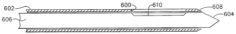
[001331 By contrast, in FIG. 6, a side aperture 600 of a sleeve 602 may be
positioned
beside a suspicious lesion so that a piercing tip 604 need not pass through
the suspicious
lesion. Locating this side aperture 602 in an MRI scan slice would seem to be
easier in
that the side aperture 600 defines a line that more readily allows orienting
an imaging
slice along its length with a geometric reference that readily shows from what
direction
CA 02569101 2006-11-20
WO 2005/112778 PCT/US2005/017775
24
tissue may be drawn into the side aperture 600 for biopsying. However, slices
that are not
ideally oriented or that pass through MRI compatible materials that may form
the sleeve
602 may still complicate accurate and expedient identification of the side
aperture 600.
To assist in this identification, an obturator 606 assists during introduction
of the sleeve
602 by substantially or completely blocking the side aperture 600 so that
tissue does not
prolapse into the side aperture 600 and impede insertion and/or cause tissue
trauma.
[00134] In some applications, it is further desirable to have a distal
opening 608 in the
sleeve 602. The obturator 606 thus advantageously includes the piercing tip
604 that
extends distally out of the distal opening 608 in the sleeve 602. The
obturator 606 further
has a lateral recess (e.g., notch, bevel, canoe dug-out) 610 aligned with the
side aperture
600 in the sleeve 602 when the obturator 606 is fully inserted therein. Being
radially
asymmetric, this lateral recess 610 provides a rapidly acquired and
interpreted reference
for locating the side aperture 600.
[00135] In FIG. 7, a side aperture 620 is formed in a sleeve 622 that has a
closed distal end
628 that forms or supports a piercing tip 624. An obturator 626 serves to
shape the
prolapse of tissue into the side aperture 600 during introduction and includes
a lateral
recess (e.g., notch, bevel, canoe dug-out) 630 aligned with the side aperture
620 in the
sleeve 622 when the obturator 626 is fully inserted therein.
[00136] In FIG. 8, an obturator 646 includes a piercing tip 644 that
extends out of the
distal opening 608 in the sleeve 602 of FIG. 6. The obturator 646 creates a
distinctive
cross section by having an upper longitudinal portion 649 and a lower
longitudinal
portion 651. The upper longitudinal portion 649 is shaped to control the
prolapse of tissue
into the side aperture 600 as well as present a readily located reference for
an MRI scan
slice.
[00137] In FIG. 9, the sleeve 622 of FIG. 7, with the closed distal end 628
formed into or
supporting the piercing tip 624, is shown having its side aperture 620 closed
during
introduction by an obturator 656 having a distinctive cross section showing an
upper
longitudinal portion 649 and a lower longitudinal portion 651. The upper
longitudinal
portion 649 has a cross sectional profile that is designed to shape the
prolapse of tissue
into the side aperture 600 as well as present a readily located reference for
an MRI scan
slice.
CA 02569101 2006-11-20
WO 2005/112778 PCT/US2005/017775
[00138] In FIG. 10, a sleeve 702 has a side aperture 700 and a closed
distal end 708 which
are formed into an asymmetric piercing tip 704 that encompasses an obturator
706. The
obturator 706 has a continuous profile formed by an upper longitudinal portion
709 and a
lower longitudinal portion 711 that create a distinctive cross section, such
as an X-shape
as depicted in FIGS. 11-12. Alternatively, the obturator 706 may have a
distinctive cross
section such as an upward longitudinal spine 715 attached to a lower
longitudinal half-
cylinder 717. It should be appreciated that the prolapse of tissue at the side
aperture
provides an MRI image return whereas in other portions of the obturator, the
air spaces
between the sleeve 702 and the obturator 706 appear similarly dark.
[00139] In FIG. 15, an obturator 806 includes a lateral notch 810 proximate
to a piercing
tip 804. Rather than relying upon tissue prolapsing under forces of gravity,
palpation or
vacuum assist, an MR1 visible insert 807 (e.g., an aqueous gel such as KY
JELLY by
JOHNSON & JOHNSON) may advantageously have sufficient stiffness to remain in
place and to prevent prolapse of tissue into a side aperture of a sleeve (not
shown in FIG.
15). In FIG. 16, instead of being laterally inserted, an obturator 826 may
include a
proximally accessed marker lumen 827 through which a marker insert 829 may be
inserted proximate to a distal piercing tip 824.
[00140] As an alternative to an added MRI visible material, in FIG. 17, an
obturator 846
includes a vacuum lumen 848 that communicates with a lateral notch 850 to draw
in
sufficient bodily fluids 851 to present an MRI visible image of the side
aperture of the
sleeve (not shown). In FIG. 18, the obturator 846 employs vacuum assist
through the
vacuum lumen 848 to prolapse tissue 853 into the lateral notch 850 to present
an MRI
visible image. In FIG. 19, the obturator 846 further includes a thin sheath
855 that is slid
overtop of the lateral notch 850 to capture an MRI visible material (e.g.,
aqueous fluid,
gadolinium solution, etc.) 857.
[00141] In FIG. 20, an obturator 876 includes a solid stylet insert 879
substantially
encompassed by a cylindrical sheath 877, except for over a lateral notch 881
formed in
the solid stylet insert 879. The cylindrical sheath 877 is distally attached
to a ceramic
asymmetric piercing tip 874.
[00142] In FIG. 21, an obturator 899 has an open distal end 894 and a
lateral aperture 890
with vacuum assisted air evacuation proximally from a marker lumen 893 formed
therein,
CA 02569101 2006-11-20
WO 2005/112778 PCT/US2005/017775
26
allowing the marker lumen 893 to fill with bodily fluids to present an MRI
visible
material.
[00143] In FIG. 22, an obturator 906 has a piercing distal end 0904 and a
lateral aperture
0900 with vacuum assisted air evacuation to allow a marker lumen 903 to fill
with bodily
fluids to present an MRI visible material.
[00144] In FIG. 23, an obturator 916 has a closed, blunt distal end 914 and
a marker lumen
918 containing an MRI visible material (e.g., gadolinium solution, aqueous
solution) 911.
An MRI dark plug 913 (e.g., collagen, nonferrous metal, plastic) is positioned
to
correspond to a side aperture of a sleeve (not shown in FIG. 23). The MRI dark
plug 913
contains longitudinal fluid leak passages 915 to allow MRI bright images to be
formed to
each side of the side aperture within the marker lumen 918.
[00145] In FIG. 24, an obturator 926 has a piercing distal end 924 and a
marker lumen 928
containing an MRI visible material (e.g., gadolinium solution, aqueous
solution) 921. An
MRI dark plug 928 (e.g., collagen, nonferrous metal, plastic), 923 is
positioned to
correspond to a side aperture of a sleeve (not shown in FIG. 24). The MRI dark
plug 923
contains longitudinal fluid leak passages 925 to allow MRI bright images to be
formed to
each side of the side aperture within the marker lumen 928.
[00146] In FIG. 25, an obturator 936 has a piercing distal end 934 and a
marker lumen 938
containing an MRI visible material (e.g., gadolinium solution, aqueous
solution) 931. A
side aperture 930 communicates with the marker lumen 938 via fluid leak
passages 935
formed in an MRI dark plug (e.g., collagen, nonferrous metal, plastic), 933
otherwise
blocking the marker lumen 938.
[00147] In FIGS. 26-37, further illustrative versions of the shape of a
sleeve and obturator
are depicted that advantageously enhance the ability to locate suspicious
lesions and to
confirm proper placement of the side aperture thereof prior to taking biopsy
samples by
presenting a closed shape during penetration that may be changed to a shape
that
corresponds to a relieved area where samples will be taken, this shape visibly
solid so as
to be readily recognizable even when viewed from various angles of imaging
slices.
[00148] This feature addresses drawbacks from relying upon the probe for
imaging.
Having a metallic substance in the imaging field may cause an artifact (local
blooming)
CA 02569101 2006-11-20
WO 2005/112778 PCT/US2005/017775
27
that may obscure the tissue of interest, such as attempting to use the biopsy
probe itself to
obturate the sleeve. Removing the probe during imaging and relying upon only
the sleeve
allows another imaging challenge to occur as an imaging slice through the
hollow sleeve
22 may pose difficulties in identifying the side aperture. Often, the MRI
compatible
material selected gives no MRI return image, just as an air-filled void
present across a
side aperture thus presenting no return.
[00149] In FIGS. 26-27, an MRI compatible biopsy system 1210 includes a
sleeve 1222
having a notch 1202 that corresponds to the location and size of the probe
side aperture of
the probe of the MRI biopsy device (not shown in FIG. 26). Moreover, the depth
of the
notch 1202 may be deeper than the probe side aperture in some instances to
accentuate
this location on the sleeve 1222 for imaging purposes.
[00150] An obturator 1224, shown in phantom in FIG. 26 in its "closed
position"
substantially blocking the notch 1202 of the sleeve 1222, may be
advantageously formed
of a thermoplastic as described with a distally presented ceramic bladed
portion 1220 that
extends through an open distal end 1221 of the sleeve 1222. Ceramic materials
perform
well in an MRI environment and hold a sharpened edge. With the notch 1202
closed by
the co-axially inserted obturator 1224, the sleeve 1222 may be inserted into
breast tissue.
[00151] In FIGS. 28-29, the obturator 1224 depicted advantageously includes
a
longitudinally bifurcated design as shown in FIGS. 28-29 wherein the lower
portion 1223
includes a dovetail channel 1225 down its length that slidingly engages a
dovetail tab
1227 extending down from an upper portion 1229 of the obturator 1224. The
ceramic
bladed portion 1220 is attached only to the lower portion 1223. As shown in
FIG. 28, the
upper portion 1229 may be proximally moved with the lower portion 1223 fully
distally
inserted into the sleeve 1222 to thereby open the notch 1202 of the sleeve
1222. Since the
obturator 1224 is solid, during the 3-4 mm image slices taken by the MRI
machine, the
lower portion 1223 of the obturator 1222 fills in the notch 1202 so that its
location may
be readily ascertained. This two-piece obturator 1224 advantageously
accommodates
sleeve lumens with complex cross sectional shapes, such as the depicted oval-
shaped
sleeve 1222 (FIG. 27).
[00152] In FIGS. 30-31, a sleeve 1322 includes an integral sharp 1320
distally attached to
its shaft 1319 that defines a circular cutter lumen 1321 and an underlying
vacuum lumen
CA 02569101 2006-11-20
WO 2005/112778 PCT/US2005/017775
28
1323. In FIGS. 32-33, a round obturator 1324 is generally rod-shaped for
insertion into
the cutter lumen 1321 but with a notch recess 1325 formed corresponding to a
notch 1302
of the sleeve 1322. Insofar as the round obturator 1324 is rotatable within
the cutter
lumen 1323, the notch recess 1325 may be selectively presented to open the
notch 1302 in
the sleeve 1322 or rotate about half a revolution to close the notch 1302.
[00153] The resulting effect in an MRI image scan is illustrated in FIGS.
34-35 wherein
selectively closing the notch 1302 in the sleeve 1322 with the obturator 1324
presents a
solid image but with little indication of where the notch 1302 is oriented. In
FIGS. 36-37,
with the obturator 1324 rotated to open the notch 1302, it is readily apparent
where the
notch 1302 is oriented.
[00154] The sleeve may be formed advantageously of a polymeric material,
either
homogenous or a composite, that is strong yet with thin walls so that the
overall outer
diameter need not be significantly larger than known biopsy probes, thereby
being
minimally invasive. The strength and small cross sectional area minimizes the
size of the
opening through the skin and thus typically avoids the need for sutures to
close, reduces
the force required to insert the probe, and minimizes trauma to breast tissue
penetrated
enroute to a suspicious lesion. The strength and rigidity advantageously
maintain an open
lumen for subsequent biopsy and other procedures therethrough. In addition,
the sleeve is
advantageously formed from materials that are biologically compatible to the
patient and
MRI compatible. Generally, the material thus does not create significant
imaging artifacts
that would obscure tissue images proximate to the sleeve 22.
[00155] Examples of polymeric materials that may be used, although not an
all inclusive
list, include polyimide, polyetherimides (e.g., ULTEMe resin by GE PLASTICS),
thermoplastic liquid crystal polymers (LCP) (e.g., VECTRA by CELANESE AG),
polyethylether ketones (e.g., PEEKTM by VITREX), polyamide, polycarbonate
(e.g.,
MAKROLON by BAYER POLYMERS), polysulfone, polyethersulfone,
polyphenylsulfone (e.g., RADEL by ROWLAND TECHNOLOGIES), and nylon and
nylon copolymers.
[00156] In FIG. 38, a piercing member (e.g., probe, multi-function
obturator) 1700 has
piercing tip 1702 as described below with regard to FIGS. 77-80B. A lateral
notch 1704 is
accentuated by an underlying MRI visible marker 1706 and communicates with a
lumen
CA 02569101 2006-11-20
WO 2005/112778 PCT/US2005/017775
29
1708 that may be used for aspiration, hemostasis, introduction of anesthesia
or
pharmacological compound, and/or a marking material. Leading and trailing
edges 1710,
1712 of the lateral notch 1704 are rounded so as to avoid trauma to tissue
during insertion
and retraction.
[00157] In FIG. 39, an alternate piercing member 1730 has a pair of MRI
visible markers
1735, 1736 that flank a lateral notch 1734 with a lower lumen 1738 aligned to
terminate
below the lateral notch 1734 and to communicate thereto via holes 1740.
Thereby,
imagability and fluid introduction / extraction is facilitated by the piercing
member 1730.
[00158] In FIG. 40, a combination of the features of FIGS. 55-56 is shown
with a further
alternate piercing member 1760 having a pair of MRI visible markers 1765, 1766
that
flank a lateral notch 1764. A marker lumen 1768 is aligned to enter a trailing
edge 1770
of the lateral notch 1764 with a leading edge 1772 of the lateral notch 1764
ramped to
eject a tool such as an inserted marker deployment tool 1769. A lower lumen
1771
terminates below the lateral notch 1764 and communicates thereto via holes
1775 for
insufflation during marker deployment or for transferal of fluids.
[00159] In FIG-. 41, a core needle 1800 having a lumen 1802 aligned to a
longitudinal
centerline thereof communicates to an open distal end 1804 for deploying core
biopsy
tools, a marker tool, wire for localization, an ablation device, etc. An
imagable marker
1806 advantageously surrounds the open distal end 1804 to assist in proper
placement of
the core needle 1800.
[00160] In FIG. 42, a polyimide process may be used to form this material
wherein a film
is formed from solution. A standard practice is to coat continuous wire by
passing wire
from a spool, through a polyimide coating solution through a furnace to a take-
up spool.
The wire usually goes through multiple processes to build up the coating
thickness. The
inline furnace or heating element drives off the solvent and causes partial
cross-linking of
the polyimide. Full cross-linking occurs usually when the desired coating
thickness has
been achieved. The full cross-linking temperature occurs at a much higher
temperature
than the temperature used during coating.
[00161] To create the free standing polyimide tube, the wire is then
removed. For example,
lengths of the coated wire may be cut with the wire pulled or drawn from both
ends to
CA 02569101 2006-11-20
WO 2005/112778 PCT/US2005/017775
stretch it, thereby reducing its outer diameter until separated from the
coating, then
withdrawing the wire. Alternatively, an easily chemical etched material may be
used for
the wire. For instance, a cooper wire may be dissolved by a persulfate
complexing
solution leaving behind a free standing polyimide tube.
[00162] Further, to create more complex cross sectional shapes (FIG. 72A-
72D) (e.g.,
oval, etc.) the polyimide tube may be placed in a form prior to a final cross-
linking heat
step. In addition, a mandrel may be inserted through the polyimide tube to
further define
the shape, especially in cooperation with compressing outer forms, such as
depicted in a
sequence of FIGS. 44A-44C for an oval and in a sequence of FIGS. 45A-45E for a
waisted oval.
[00163] In FIGS. 46, 47A-47B, follow-on processes to create a side aperture
at its distal
end and/or mounting holes at its proximal end may then be formed. For
instance, laser
cutting by an eximer or YAG laser may form desired perforations. Further, an
eximer
laser may not be used to form through holes but also reliefs sufficient to
create enough
mechanical interference with over-molded parts to ensure assembly integrity
during
normal loading and tension. Full perforations may be used to allow an over-
molded part,
such as proximal end mounting mechanisms, to flow through the holes before
hardening.
[00164] To achieve holes in the tube of FIG. 43, several methods may be
employed. For
instance, an eximer or YAG laser machine may create the perforations (FIG.
47A). The
eximer laser may also be programmed to create not only through holes, but also
reliefs.
Reliefs may be substituted to create sufficient mechanical interference with
an
overmolded part to ensure assembly integrity during normal loading and tension
(FIG.
47B). As another example, a punch or die-cut process may be integrated into
the forming
mold. The parts may be cut, trimmed and punched followed by heat treatment in
the same
form.
[00165] The forming molds advantageously should be both hard and have high
thermal
conductivity. Steel, while hard, has low thermal conductivity. Copper and
brass, by
contrast, have high thermal conductivity, but are softer. An alloy of hardened
aluminum
may be a suitable material for the forming molds with steel inserts for
punching holes.
CA 02569101 2006-11-20
WO 2005/112778 PCT/US2005/017775
31
[00166] A sheath may also be formed from a braided composite. Individual
fibers of the
braid may be wound on an initial layer of polyimide and then sealed in a layer
of
polyimide. The braid may be of an MRI compatible ceramic fiber, such as NEXTEL
by
3M.
[00167] Portions of the sleeve and/or obturator may be formed from
materials chosen for
their imagability, either dark or bright. Under most standard MRI scan
sequences used to
image breast tissue for possible cancer, known engineering plastics appear
dark or have
low contrast, which may cause problems when identifying such components for
localizing
and diagnostic purposes. Consequently, in addition to considerations described
above
when forming a sleeve of sufficient strength and MRI compatibility, it may be
advantageous to substitute or augment material that is bright to an MRI
machine but that
does not create a significant artifact. In addition or as an alternative, an
overmold or coat
or insert material that appears bright to an MRI machine may be formed over
structural
"dark" material. In addition or as an additional alternative, a "dark"
material chosen for
strength or other reasons may be overmolded or coated or inserted with
materials that
absorb a contrast enhanced or bright fluid. In addition or as yet another
alternative, a
composite or multilayered material may be formed with some layers chosen for
properties
such as strength and others chosen for their characteristic of being visible
to the MRI
machine.
[00168] Particular patterns of marker bands, for instance, may be placed
inferior to the
side aperture of the sleeve, or in spaced rings proximal to or distal to the
side aperture
about the sleeve. As an example, Dy203 or Fe203 may be mixed with an ink and
then
printed onto portions of the sleeve 22 or used to fill recessed grooves on the
obturator 24
or stylet. Such patterns may also be created by dispersing Dy203 or Fe203 as
filler into a
thermoplastic so that isit may be applied to the sleeve 24 and/or obturator by
reflow or
thermal bonding. Yet another approach is to insert mold Dy203 or Fe203 into
the device,
such as by loading a molded/extruded component plastic (e.g., PEEK, ULTEM) and
attach (e.g., over mold a ring of 30% Dy203 in PEEK).
[00169] As yet a further alternative, regions of material may be capable of
being infused or
hydrated with a water based solution and/or a contrast agent (e.g., gadolinium
chelate)
that would thus appear bright when imaged. As yet another alternative, regions
of
CA 02569101 2006-11-20
WO 2005/112778 PCT/US2005/017775
32
material, such as infusion or hydration, may occur immediately before use or
such
material may be pre-hydrated and aseptically packaged.
[00170] In particular, certain polymers that appear bright to an MRI
machine may be
selected to include synthetic water soluable polymers that have high alcohol
or carboxilic
acid functionality. For example, cellulose derivatives include carboxymethyl
cellulose,
ethyl cellulose, hydroxyethyl cellulose, carboxymethyl hydroxyethyl cellulose,
ethylhydroxyethyl cellulose, and methyl cellulose. As another example,
acrylates include
polyacrylic acid salts and polyacrylamide. For yet another example, other
artificial
materials include polyvinyl alcohol (PVA), polyvinyl methyl ether,
polyvinylpyrrolidone
(PVP), and poly(ethylene) oxide (PEO). As yet a further example, natural
products and
derivatives include cornstarch, gelatin, dextrins, alginates, casien, collagen
(e.g., bovine,
etc.) and natural gums (e.g., xanthum, tragacanth, karaya, etc.). As yet an
additional
example, biopolymers include polylactic acid, di-lactide-co-glycolide (PLG)
(i.e., as an
example of lactide isomers (D, L, DL) (MP = 225-230 C)), polycaprolactone (MP
= 60
C), lactates and gluconates, polydioxanone, polyglactin (i.e., suture
materials).
[00171] Other polymers that appear bright to an MRI machine include
silicone based
materials such as siloxanes functionalized with hydroxyl (-OH) groups and
carboxylic
acid groups and such as silicones (i.e., both fluid and gum rubbers).
[00172] In an illustrative version when making polymeric materials image
without
excessive artifact in MRI, dysprosium oxide (Dy203) or hermatite (Fe203) was
dispersed
as a filler in a thermoplastic carrier that can be thermoformed (e.g.,
extruded, molded,
etc.). A marker thus formed, when integrated into a device such as the sleeve
22 or
obturator 24, improves device visibility under MRI (e.g., gradient echo EPI,
flash, real-
time true FISP). In particular, Dy203 (35%) was dispersed in Rilsan
Polyamides (75%)
ATOFINA Chemicals, Inc. This combination was extruded into thin-walled (i.e.,
0.002
inch) tubing, which was quite visible using Flash. Further, Flash appears to
create the best
visibility for susceptibility devices (includes Dy203 and Fe203), EPI was less
visible, and
real-time true FISP was not visible.
[00173] Other polymers that appear bright to an MRI machine include
hydrophilic
polymer and polymeric foams such as urethane foams that rapidly absorb
moisture when
adding hydrophilic block-copolymer segments are added into the urethane
backbone or
CA 02569101 2006-11-20
WO 2005/112778 PCT/US2005/017775
33
use surface functionalization such as that effected by plasma oxidation or
chemical
oxidation. Similarly, other polymers may be foamed such as starch with linear
low
density polyethylene, expanded polytetrafluoroethylene (PTFE), or other
materials (e.g.,
polyimides, polyolefins, polystyrenes, polyesters, nylons, acrylics,
acrylates,
polycarbonates, melamines, polyvinylchloride, polyvinylacetate).
[00174] As implementations wherein aqueous based solutions are infused or
hydrated into
such materials, such solutions include gadolinium based compounds for Ti
enhancement
in solution including diethylene triamenepentaacetic acid (DTPA), gadoteridol
(GD-HP-
DO3A) (nonionic), gadodiamide (GD-DTPA-BMA) (nonionic), and GdDOTA (ionic).
Such solutions also include iron-based solutions for T2 enhancement such as
Feridex
(super paramagnetic agent).
[00175] Accentuating the side aperture 102 of the sleeve 22 has been
discussed above as in
the choice of materials or shaping of the obturator that selectively closes
the side aperture
102. It is also mentioned above that specific regions of the sleeve 22 may be
accentuated.
With regard to the latter, marking the side aperture 102 with material that is
bright under
MRI imaging may be accomplished with commercially available contrast agents to
leverage existing capital equipment and supply channels. Examples of such
contrast
agents are gadolinium (Gd+3) (e.g., MAGNEVISTO (gadopentetate dimeglumine) by
BERLEX); iron (Fe+3) (e.g., FERIDEX IV (ferumoxides injectable solution); and
manganese (Mn+2) MnDPDP (e.g., TESLASCANTm Mangafodipir by AMERSHAM
HEALTH). A matrix of a polymer may swell in the presence of water to create a
contained, hydrated environment for the contrast agent. These polymers would
be
permeable to water, but have limited permeability of the contrast agent
molecules! The
contrast agents may be chemically bound to the matrix to reduce or limit their
migration
out of the matrix. Examples of polymers suitable for such a matrix include
hydrogels,
urethane acrylates with hydrophilic blocks, latex paints/emulsions, coatings
loaded with
hydrophilic particulate such as silica particles and particle aglomerates.
[00176] A void within an obturator may include a vent and a septum.
Contrast agent may
be injected through the septum with air vented through the vent. Hydrophilic
foam or
cellulose material (e.g., cotton) within the void may be used to better retain
the contrast
CA 02569101 2006-11-20
WO 2005/112778 PCT/US2005/017775
34
agent. Alternatively, contrast chelate may be preloaded onto the hydrophilic
foam or
cellulose material and hydrated during the procedure.
[00177] As an alternative or an addition to materials that are bright under
MM, active
marker band technologies may be incorporated to illuminate a side or distal
aperture in
the sleeve 22. Examples of active illumination used in different applications
are described
in U.S. Pat. Nos. 5,211,165; 5,307,808; 5,318,025; 5,437,277; 5,443,066;
5,445,150;
5,715,822; 5,882,305 and 6,289,233. Coils are formed proximate to the sampling
aperture, such as side aperture 102 with electrical connections formed along
the length of
the sleeve 22. Polyimide is a particularly good material choice for forming a
substrate for
such coils and electrical connections because of significant development of
technology
and processes to form thin film electronic circuits on polyimide. Electrical
isolation may
be achieved with overcoats of another layer of polyimide. An inductive coil
about the
base of the sleeve 22 that is in electrical communication with these marker
bands would
allow RF coupling to these coals and provides RF isolation for the patient.
Alternatively,
a dedicated integrated circuit and power source (e.g., battery, capacitor) may
be integrated
into the sleeve 22 to eliminate the need for external excitation. These marker
band coils
may be in parallel or serial or separately excited. As another alternative,
two coils may be
serially arranged but with a center tap.
[00178] In some applications, it may be desirable to incorporate
thermistors or
thermocouples that may be monitored for an unacceptable temperature rise
(e.g.) 4 C) for
automatic shutdown. As a further alternative, optical converters may be
incorporated into
the sleeve so that light fibers may communicate a signal in and out.
[00179] Similar considerations are applicable to the piercing portion of
the sleeve or
obturator; however, the needs for piercing tissue may lead to other choices.
As an
introduction, metallic components used for MM safe medical devices must be
biocompatible and not interact with the strong magnetic fields used during MM
imaging.
Standard 300 and 400 series stainless steels are ubiquitous in medical device
design.
These materials combine the features of corrosion resistance,
biocompatibility, hardness
and tensile properties. These materials are primarily ferrous. The 300 series
materials
have less interaction with magnetic fields than the 400 series materials, but
have lower
hardness properties, which limits their utility for sharp edges for cutting
and/or
CA 02569101 2006-11-20
WO 2005/112778
PCT/US2005/017775
penetrating tissue. All 300 and 400 series materials have significant
concentrations of
iron, which limits their utility for MRI imaging applications.
[00180] Iron Alloys: There is at least one ferrous, austenitic alloy, which
remains non-
magnetic even after severe forming operations, Super Alloy Nitronic. Other
related
materials include Carpenter 22Cr-13Ni-5Mn, HPA 50, XM-19. Alloy 316 is also
relatively non-magnetic, but becomes more magnetic as it is work hardened. The
alloy
compositions are as follows:
CA 02569101 2006-11-20
WO 2005/112778 PCT/US2005/017775
36
TABLE 1 Steel Composition Range (%)
Element Nitronic 50 316L Ideal
Carbon 0.06 max 0.03 max 0.06 max
Manganese 4-6 2.0 2-6
Phosphorus 0.04 max 0.045 max 0.045 max
Sulfur 0.03 max 0.03 max 0.03 max
Silicon 1.0 max 1.0 max 1.0 max
Chromium 20.5-23.5 16-18 16-24
Nickel 11.5-13.5 10-14 10-14
Molybdenum 1.5-3 2-3 1-3
Copper
Cobalt 0.1-0.3 0.3 max
Titanium
Columbium 0.1-0.3 0.3 max
Aluminum
Tantalum
Vanadium 0.1-0.3 0.3 max
Tungsten
Boron
Nitrogen 0.2-0.4 0.4 max
Iron Balance Balance Balance
[00181] The ideal range is that range into which iron based alloys need to
fall to have
minimal magnetic properties.
[00182] Cobalt Alloys: Cobalt alloys are an excellent alternative. These
alloys are hard
and do not interact strongly with the magnetic fields. Examples of such alloys
include L-
605 and MP-35. Cobalt alloys are optimized for either wear resistance, high
temperature
use and/or corrosion resistance. For breast biopsy tools, the wear resistance
and corrosion
resistance properties are of greatest interest. The primary alloying element
to provide
these properties is the addition of chromium (US 873,745). Molybdenum and
tungsten are
outstanding strengthening agents. The addition of carbon improves the wear
resistance
significantly. The addition of up to 2.4% carbon results in the formation of
carbides. An
example of this alloy is the trade name, Stellite. An alternate method for
improving wear
is the addition of the combination of molybdenum and silicon. An example of
this alloy is
the trade name Tribaloy. This alloy has been deposited successfully as a thin
film.
CA 02569101 2006-11-20
WO 2005/112778 PCT/US2005/017775
37
[00183] The addition of nickel was found to improve the high temperature
performance.
An example of this alloy is Stellite 21 with approximately 2.5% nickel. Later
alloys such
as the X-40 and L-605 have increasing nickel content to around 10%. In general
alloys
with the following composition ranges are optimum for Co based, high tensile
strength,
high hardness materials:
TABLE 2 Composition Range (%)
Element L-605 MP-35 CCM Ideal
Carbon 0.05-0.15 0.025 max 0.1 max 2.4 max
Manganese 1-2 0.15 max 1 max 0-2
Phosphorus 0.03 max 0.015 max 0.2 max
Sulfur 0.03 max 0.01 max 0.05 max
Silicon 0.4 max 0.15 max 1 max 0-2
Chromium 19-21 19-21 26-30 19-35
Nickel 9-11 33-37 1 max 0-40
Molybdenum 9-11 5-7 0-15
Copper 0-1
Cobalt Balance Balance Balance
Titanium 1 max 0-2
Columbium/Niobium 0-1
Aluminum 0-1
Columbium+Tantalum 0-1
Vanadium r 0-1
_
Tungsten 14-16 0-20
Boron 0.01 0-0.05
Nitrogen 0.25 0.25 max
max
Iron 3 max 1 max 0.75 5 max
max
[00184] Nickel Based Alloys: Nickel-Chromium-Molybdenum alloys are another
approach to hard, non-magnetic metal alloys. Some members of this alloy class
have
greater than 5% iron (Inconel 600) and nickel based alloys even without iron
can have
significant magnetic properties. The composition and processing of the alloy
is key to its
. magnetic and physical properties. Some alloys such as Inconel 625, have
Rockwell
hardness exceeding 95Rb.
CA 02569101 2006-11-20
WO 2005/112778 PCT/US2005/017775
38
TABLE 3 Composition Range (%)
Element Inconel 600 Inconel M252 Ideal
X750
Carbon 0.08 0.1 0.1 2 max
Manganese 0.5 1.0 1.0 0-2
Phosphorus 0.2 max
Sulfur 0.05 max
Silicon .25 0.5 0.7 0-2
Chromium 15.5 15. 19 10-20
Nickel 76 72 53.5 Balance
Molybdenum 10 0-15
Copper 0.25 0-1
Cobalt 1.0 10
Titanium 2.5 2.5 0-2
Columbitun/Niobium 0-1
Aluminum 0.7 0.75 0-2
Columbium+Tantalum 0-1
Vanadium 0-1
Tungsten 0-2
Boron 0-0.05
Nitrogen 0.25 max
Iron 8 7 2 10 max
[00185] Composite Approaches: Soft metals, such as titanium or fully
annealed 316 SS
have appropriate magnetic properties, but have poor hardness and thus poor
cutting
ability. These materials can be locally hardened at the cutting or penetrating
surface by
the follow processes: (1) Brazing, welding, or joining a hard material edge to
the soft
metal; (2) Vapor deposition (chemical, vacuum, etc) of a hard material such a
titanium
nitride; (3) Ion beam implantation; (4) Localized heat/work hardening via
laser or
frictional heating; (5) Or a combination of the above methods.
[00186] Non-Metallic Materials Options: Other non-metallic materials useful
for creating
sharp, cutting surfaces include the following amorphous/ceramic materials: (1)
Alumina;
(2) Zirconia (including yttria stabilized); (3) Silica. Single crystal
materials include: (1)
Silicon; (2) Germanium; (3) Carbon in the diamond form; (4) Aluminum in the
sapphire
form; (5) Ruby. The single crystal cutting edges may be created using the
single crystal
properties of the materials. Preferential etches, such as alcohol-KOH on 1,0,0
silicon
wafers, can be used too pattern precise angles and thus sharp edges.
CA 02569101 2006-11-20
WO 2005/112778 PCT/US2005/017775
39
[00187] Penetrating Member Geometries: The blade geometry is important in
the
optimization of the force to penetrate tissue. The early pyramidal design on
trocars has
recently been superceded by flat blade designs. The theory of point and
cutting angles
date back to Augur bits in 1800's. Cutting theories have always been studied,
developed
and refined for wear issues, etc., in recent years. The key factor that
governs this
optimization is the geometry at the tip as torque and thrust force (the amount
surgeon
pushes the trocar) is fixed for a given diameter of blade. The majority
(almost 90%) of
penetration forces is controlled by the tip as it separates the layers of
tissue. Using lower
penetration forces is beneficial as this causes less pain. There is 120 degree
motion of
torque in both direction while inserting the blade. The thrust force with
which the blade is
pushed is not measured. An assumption may be made that the trocars are pushed
at
around 5 lbs. The cutting blade is the major element of the tip, which
separates (cuts) the
tissue. In the current design (FIG. 48) there is sharp cone angle of 30 to 35
degrees with a
flat blade perpendicular to the surface. This invention explores to optimize
the
optimization of the tip design with offset cutting edges with a cutting angle
and a
secondary flat point angle at the center, as depicted in FIGS. 49A-49B.
[00188] Definitions: Dynamic cutting angle (adyn): The angle measured in a
plane through
a point on the cutting edge and perpendicular to the horizontal line that
passes that point
and intercepts with the drill center axis, between the rake face and normal
line of that
plane which contains both the cutting edge and the cutting velocity vector.
The cutting
velocity vector is the vector sum of the rotary cutting velocity vector and
feed velocity
vector. This is the cutting angle that may be used in separating tissue
layers, with the
geometry for positive angles depicted in FIG. 50 and for negative angles
depicted in FIG-.
51.
[00189] As explained above at any given point in the cutting blade there
are two velocity
vectors. In the current design a = 0 as the blade is perpendicular to the
cutting edge.
Assume the cutting edge of the blade is divided into number of small elements
(N). Each
element is assumed to experience orthogonal cutting. The method of calculating
dynamic
rake angle at any instant and spatial position on the cutting edge can be
developed based
of geometric factors. Torque at each instant can be determined by the
following equation:
N
;own = E [Fp, Fn(f(ad(0,woc(i))x r(i))1
CA 02569101 2006-11-20
WO 2005/112778 PCT/US2005/017775
Where ad (Dynamic Cutting Angle), and r(i) (radius of each element from the
axis of the
drill) is varying for each element on the cutting edge.
[00190] The difference between the current design and proposed design is
that width of
cutting edge (WOC) change, cutting angles may be steeper (range from 40 to 60
degrees)
This is a converse problem of cutting as given lin-lb torque and X lbs thrust.
What is the
best geometry at the tip to get lower penetration force. This can be
analytically developed
and tested in the wet lab.
Problem statement is: Ttotal= constant ¨ Reduce Fõ based of geometry.
This is possible with offset cutting edge and making more aggressive cutting
angles from
40 to 60 degrees.
[00191] The cutting edge can also have multiple blades like 4 to increase
the WOC. The
cutting edge shall not be sharp to avoid ploughing. It may have a 5 thousand
radius to
optimize penetration forces. The flat blade can be further optimized as
follows as depicted
in FIGS. 52A-52B.
[00192] In FIGS. 53-57, an obturator 3000 incorporates a flat blade 3002
onto a hollow
shaft 3004 that provides a multi-function lumen 3006. In FIG. 54, the flat
blade 3002 is
attached within a vertical slot 3008 formed between two distal ramped
triangular supports
3010, 3012. A proximal end 3014 of the hollow shaft 3004 provides a pressure
fitting
3016 for using the lumen 3006 for pneumatic or fluid transfers to an imagable
side notch
3018 proximate to the flat blade 3002. In FIGS. 53, 55, exterior engagement
features on
the proximal end 3014 include a circumferential raised ring 3020 proximal to a
circumferential ring slot 3022. In FIG. 55, a vent hole 3024 through an
opposite lateral
side to the imagable side notch 3018 allows equalization of pressure within a
sleeve or the
use of a vacuum lumen in the sleeve (not shown in FIGS. 53-57). In FIGS. 56,
57, a top
guide slot 3026 passes longitudinally down the proximal portion 3014 of the
hollow shaft
3004 so that engagement with a sleeve may be keyed to align the imagable side
notch
3018 with a side aperture in the sleeve. In FIGS. 53, 55, rounded leading and
trailing
edges 3028, 3030 of the imagable side notch 3018 minimize tissue trauma.
Alternatively,
the top guide slot 3026 may allow visual indexing so that confirmation may be
made that
the imagable side notch 3018 is rotated out of alignment with a side aperture
during
penetration to prevent tissue entering the image side notch 3018. Thereafter,
the imagable
CA 02569101 2006-11-20
WO 2005/112778 PCT/US2005/017775
41
side notch 3018 may be rotated into alignment for imaging confirmation and/or
use of the
multi-function lumen 3006.
[00193] In FIGS. 58-60, an obturator 3100 incorporates a flat blade 3102
onto a solid shaft
3104. In FIG. 59, the flat blade 3102 is attached within a vertical slot 3108
formed
between two distal ramped triangular supports 3110, 3112. An imagable side
notch 3118
proximate to the flat blade 3102 is positioned to correspond with a side
aperture of a
subsequently inserted biopsy device (not shown in FIGS. 58-60). In FIGS. 58-
59, rounded
leading and trailing edges 3128, 3130 of the imagable side notch 3118 minimize
tissue
trauma. With particular reference to FIG. 60, a trough ("canoe") recess 3132
is formed
into the imagable side notch 3118 to further accentuate imability. The solid
shaft 3104
has a cross sectional egg shape to correspond to probes including a
cylindrical cutter tube
with a narrower underslung "air scoop" shaped vacuum lumen. In FIGS. 58-59,
longitudinally spaced imaging cavities, depicted as cylindrical vertical wells
3140, 3142,
3144, 3146, have decreasing diameters moving proximally to the trough (canoe)
recess
3132 to further accentuate the imagable side notch 3118.
[00194] In FIGS. 61-64, an obturator 3200 incorporates a flat blade 3202
onto a solid shaft
3204. In FIG. 62, the flat blade 3202 is attached within a vertical slot 3208
formed
between two distal ramped triangular supports 3210, 3212. Returning to FIGS.
61-63, an
imagable side notch 3218 proximate to the flat blade 3202 is positioned to
correspond
with a side aperture of a subsequently inserted biopsy device (not shown in
FIGS. 61-64).
In FIGS. 61-62, rounded leading and trailing edges 3228, 3230 of the imagable
side notch
3218 minimize tissue trauma. In FIGS. 61-63, a trough ("canoe") recess 3232 is
formed
into the imagable side notch 3218 to further accentuate imability. The solid
shaft 3204
has a cross sectional eliptical shape to correspond to probes including a
cylindrical cutter
tube with an underslung "air scoop" shaped vacuum lumen. In FIGS. 61-62 and
64,
longitudinally spaced imaging cavities, depicted as longitudinal slats 3240,
3242, 3244
moving proximally to the trough (canoe) recess 3232 to further accentuate the
imagable
side notch 3218. Each slat 3240-3244 communicates to the top of the hollow
shaft 3208
through respective distal and proximal ports 3246, 3247 for filling with a
fluid while
venting trapped air. With particular reference to FIG. 64, the distal
longitudinal slat 3240
has a cylindrical cross section. The middle longitudinal slat 3242 has a
cylindrical cross
section that corresponds to a lower portion of the distal longitudinal slat
3240. The
CA 02569101 2006-11-20
WO 2005/112778 PCT/US2005/017775
42
proximal longitudinal slat 3244 has a cylindrical cross section that is
laterally narrower
than the other longitudinal slats 3240, 3244 and the same vertical height but
slightly
upwardly offset from the middle longitudinal slat 3242.
[00195] In FIGS. 65-68, an obturator 3300 incorporates a flat blade 3302
onto a solid shaft
3304. In FIG. 66, the flat blade 3302 is attached within a vertical slot 3308
formed
between two distal ramped triangular supports 3310, 3312. Returning to FIGS.
65-67, an
imagable side notch 3318 proximate to the flat blade 3302 is positioned to
correspond
with a side aperture of a subsequently inserted biopsy device (not shown in
FIGS. 65-68).
In FIGS. 65-66, rounded leading and trailing edges 3328, 3330 of the imagable
side notch
3318 minimize tissue trauma. In FIGS. 65-67, a trough ("canoe") recess 3332 is
formed
into the imagable side notch 3318 to further accentuate imability. The solid
shaft 3304
has a cross sectional egg shape to correspond to probes including a
cylindrical cutter tube
with a narrower underslung "air scoop" shaped vacuum lumen. In FIGS. 65-66 and
68,
longitudinally spaced imaging cavities, depicted as longitudinal slats 3340,
3342, 3344
moving proximally to the trough (canoe) recess 3332 to further accentuate the
imagable
side notch 3318. Each slat 3340-3344 communicates to the top of the hollow
shaft 3308
through respective distal and proximal ports 3346, 3347 for filling with a
fluid while
venting trapped air. With particular reference to FIG. 68, the distal
longitudinal slat 3340
has a vertically-aligned cylindrical cross section. The middle longitudinal
slat 3342 has a
circular cross section vertically top aligned with the distal longitudinal
slat 3340 and
having a diameter less than the vertical height but larger than the lateral
width of same.
The proximal longitudinal slat 3344 has a circular cross section having the
same diameter
as the lateral width of the distal longitudinal slat 3340 and vertically
bottom aligned with
the middle longitudinal slat 3342.
[001961 In FIGS. 69-75, confirmation was obtained that sufficient imaging
contrast was
obtained with a "dark" MRI compatible materials for an obturator shaft used
with MRI
compatible sharp tips overmolded with high modulus, thermoplastic engineering
resins
such as PEEK, Radel, or Liquid Crystal Polymers (LCPs) such as VECTRA.
"Bright"
viscoelastic materials and/or water obsorbent/containing polymers at
appropriate places
made locating a side aperture of a catmula (e.g., detached probe of a core
biopsy device or
sleeve sized to receive the probe of a core biopsy device).
CA 02569101 2006-11-20
WO 2005/112778 PCT/US2005/017775
43
[00197] In FIG. 69, an MRI image of a left side of an obturator having a
lateral notch with
30 degree corners shows that sufficient contrast against tissue may be
obtained with an
MRI slice passing through the lateral notch.
[00198] In FIG. 70, a similar result is provided with a more gradual
transition of an
obturator with 60 degree corners.
[00199] In FIG. 71, an MRI image of a left side of an obturator having a
lateral notch with
a canoe dugout.
[00200] In FIG. 72, an MRI image of a left side of the obturator of FIG. 53
with a lumen
therein is filled with aqueous fluid.
[00201] In FIG. 73, an MRI image of a left side of the obturator of FIG. 53
shows insertion
of a water soaked collagen plug into the lumen.
[00202] In FIG. 74, an MRI image of a left side of the obturator of FIG. 58
is filled with an
aqueous gel (e.g., KY JELLY available from JOHNSON & JOHNSON).
[00203] In FIG. 75, an MRI image of a left side of the obturator of FIG. 61
has slats filled
with gadolinium.
[00204] It would be desirable to have disposable fiducial instruments that
advantageously
are fillable by the end user and may even be disposable. Thereby, clinical
flexibility is
enhanced by allowing the empty fiducial instrument to have extended shelf
life,
simplified sterilization processes, simplified storage (e.g., broader
temperature range),
and reduced packaging requirements. In addition, the end user may select a
contrast agent
or other imagable material.
[00205] While the present invention has been illustrated by description of
several
embodiments and while the illustrative embodiments have been described in
considerable
detail, it is not the intention of the applicant to restrict or in any way
limit the scope of the
appended claims to such detail. Additional advantages and modifications may
readily
appear to those skilled in the art. For example, other imaging modalities may
benefit from
aspects of the present invention.
[00206] As another example, various shapes of imagable apertures may be
incorporated
into a lateral surface proximal to where a side aperture of a cannula is
positioned. For
CA 02569101 2006-11-20
WO 2005/112778 PCT/US2005/017775
44
instance, instead of cylindrical wells, wells having other cross sectional
shapes may be
incorporated (e.g., triangular, oval, square, rectangular, octagonal, etc.).
[00207] As another example, rather than a biopsy device based upon lateral
lumen vacuum
assisted biopsy with an asymmetric needle, applications consistent with
aspects of the
invention may include an axisymmetric needle with vacuum assistance provided
circumferentially, coaxially or medially. Further, in addition to
accommodating the
axisymmetric MAMMOTOME lateral lumen, an obturator may also be shaped to
accommodate a cylindrically symmetric design.
[00208] What is claimed is: