Note: Descriptions are shown in the official language in which they were submitted.
CA 02582751 2007-03-21
SECONDARY LOCK FOR A DOWNHOLE TOOL
BACKGROUND OF INVENTION
Field of the Invention
The invention relates generally to methods and apparatus for drilling and
completing
well bores. More specifically, the invention relates to methods and apparatus
for an
secondary lock for a downhole tool.
Background Art
In the drilling, completing, or reworking of oil wells, a great variety of
downhole
tools are used. For example, but not by way of limitation, it is often
desirable to seal tubing
or other pipe in the casing of a well, such as when it is desired to pump
cement or other slurry
down the tubing and force the cement or slurry around the annulus of the
tubing or out into a
formation. In some instances, perforations in the well in one section need to
be isolated from
perforations in a second section of the well. Typically, the wellbore is lined
with tubular or
casing to strengthen the sides of the borehole and isolate the interior of the
casing from the
earthen walls therearound. In order to access production fluid in a formation
adjacent the
wellbore, the casing is perforated, allowing the production fluid to enter the
wellbore and be
retrieved at the surface of the well. In other situations, there may be a need
to isolate the
bottom of the well from the wellhead. It then becomes necessary to seal the
tubing with
respect to the well casing to prevent the fluid pressure of the slurry from
lifting the tubing out
of the well or for otherwise isolating specific zones in which a wellbore has
been placed. In
other situations, there may be a need to create a pressure seal in the
wellbore allowing fluid
pressure to be applied to the wellbore to treat the isolated formation with
pressurized fluids or
solids. Downhole tools, referred to as packers and bridge plugs, are designed
for the
aforementioned general purposes, and are well known in the art of producing
oil and gas.
Traditional packers include a sealing element having anti-extrusion rings on
both
upper and lower ends and a series of slips above and/or below the sealing
element. Typically,
a setting tool would be run with the packer to set the packer. The setting may
be
accomplished hydraulically due to relative movement created by the setting
tool when
subjected to applied pressure. This relative movement causes the slips to move
up cones and
extend into the surrounding tubular. At the same time, the sealing element may
be
2
CA 02582751 2007-03-21
compressed into sealing contact with the surrounding tubular. The set may be
held by a body
lock ring, which may prevent reversal of the relative movement.
Conventional bridge plugs are mechanical devices including an anchoring
mechanism
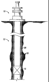
and compressive set resilient packoff seals. FIG. I shows a section view of a
well 10 with a
wellbore 12 having a bridge plug 15 disposed within a wellbore casing 20. The
bridge plug
15 is typically attached to a setting tool and run into the hole on wire line
or tubing (not
shown), and then actuated with, for example, a pyrotechnic or hydraulic
system. As
illustrated in FIG. 1, the wellbore is sealed above and below the bridge plug
so that oil
migrating into the wellbore through perforations 23 will be directed to the
surface of the well.
FIG. 2 is a partial cross sectional view of a typical bridge plug 50. The
bridge plug 50
generally includes a body portion 80, a sealing member 52 to seal an annular
area between
the bridge plug 50 and the inside wall of casing (not shown) therearound and
frangible slips
56, 61. The sealing member 52 is disposed between an upper retaining portion,
or cone, 55
and a lower retaining portion, or cone, 60. In operation, axial forces are
applied to frangible
slip 56 while the body 80 and frangible slip 61 are held in a fixed position.
As the slip 56
moves down in relation to the body 80 and slip 61, the sealing member 52 is
actuated, and the
frangible slips 56, 61 are driven up cones 55, 60. In the bridge plug of FIG.
2, the frangible
slips 56, 61 are "uni-directional" and are most effective against axial forces
applied to the
bridge plug in a single direction. The movement of the cones and slips also
axially compress
and radially expand the sealing member 52, thereby forcing the sealing portion
radially
outward from the plug to contact the inner surface of the wellbore casing. The
compressed
sealing member 52 provides a fluid seal to prevent the movement of fluids
across the bridge
plug.
In the past, downhole tools, including compression-set packers and bridge
plugs with
locking features, have been used to seal against the inside of the well casing
or wellbore. In
such downhole tools, slips are mechanically actuated to anchor the tool to the
casing wall (or
to the uncased wellbore). The elastomeric sealing element may then be
energized by
compressing the elastomeric sealing element between upper and lower cones. A
lock ring
having a ratchet system is often used to prevent the cones from slipping away
from the seal
energizing position.
It has been found that downhole tools may leak at high pressures unless they
include a
means for increasing the seal energization, such as a pressure responsive self-
energizing
3
CA 02582751 2007-03-21
feature. Leakage occurs because even when a high setting force is used to set
the downhole
tool seals, once the setting force is removed, the ratchet system of the lock
ring will retreat
slightly before being arrested by the locking effect created when the sets of
ratchet teeth mate
firmly at the respective bases and apexes of each. This may cause a loosening
of the seal.
Downhole tools are also particularly prone to leak if fluid pressures on the
packers are cycled
from one direction to the other.
There have been several suggested solutions in the past to the general problem
of
pressure-deactivation of well packers. Each of these proposed solutions
attempts to increase
the seal energizing force when fluid pressure is applied, in some cases from
annulus pressure
above or below the packer, and in at least one case from pressure applied
through the central
bore of the inner mandrel. An example of one such system system is disclosed
in U.S. Pat.
No. 4,224,987, issued Sept. 30, 1980, to Allen. Allen discloses a well packer
using a
combination of an upper movable sleeve and inner mandrel movement, to increase
seal
element energization from annulus pressure applied from above, and a movable
piston to
increase seal element energization from annulus pressure applied from below.
An upper shoe
and sleeve are slidably retained on the inner mandrel in engagement with the
seal elements,
and are responsive to fluid pressure applied from above. The upper shoe and
sleeve move
down in response to such pressure, further compressing the packer elements.
From below,
annulus pressure acts upwardly on a telescoping piston, forcing it further
into engagement
with the packer seals. Thus, the Allen device uses movable shoes/pistons both
above and
below the seal elements, and requires a plurality of moving sleeves, pistons,
and other parts
both above and below the seal elements in order to effect the disclosed self-
energizing of the
seals. The Allen seal elements are actuated in such a way that the movable
sleeves/pistons
which effect the increased energization engage the seal elements across only a
part of their
diameters and may cause extrusion of the elastomeric members around them at
the upper and
lower extremities of the stack of seal elements. Such extrusion around the
sleeves and
pistons may cause uneven stresses in or even damage to the seal elements, and
could lead to
seal failure.
Another approach to self-energization of a well packer due to pressure applied
from
both above and below the packer is disclosed in U.S. Pat. No. 3,459,261,
issued Aug. 5, 1969,
to Cochran. The Cochran device discloses a floating sleeve on which the seal
element is
mounted, the floating sleeve being slidable between abutments and responsive
to fluid
pressure applied from above and below the packer to increase the endwise
compression of the
4
CA 02582751 2007-03-21
seal. Like the Allen device, the Cochran packer thus has movable sleeves both
above and
below the seal element. The sliding sleeve of Cochran, however, must remain
free to move
up and down in order to effect self-energizing. Accordingly, in the event of
pressure cycling,
the sleeve may become stuck or may be prevented from moving fully or properly
in one
direction or the other to energize the seal.
Another approach to increasing seal energization is disclosed in U.S. Pat. No.
4,423,777, issued Jan. 3, 1984, to Mullins. The Mullins patent discloses a
pressure chamber
within a packer with dual-acting pistons, one piston setting the slips and the
other piston
compressing the seal elements. In the event that the seal elements begin to
loosen, for
example through extrusion, the Mullins patent discloses pressuring up through
the central
bore of the tool to the pressure chamber therewithin, thereby forcing the
upper piston further
into engagement with the seal elements and increasing the energization
thereof.
Accordingly, there exists a need for a bridge plug which may effectively seal
a
wellbore and remain effective when subjected to pressures from above or below
while in use.
Additionally, there exists a need to effectively self-energize a seal on a
downhole tool and
maintain the energization of the seal when subjected to pressures from above
or below the
downhole tool.
SUMMARY OF INVENTION
In one aspect, the present invention relates to a downhole tool that includes
a mandrel,
a sealing element disposed around the mandrel, an upper cone disposed above
the sealing
element and a lower cone disposed below the sealing element, an upper slip
assembly
disposed above the upper cone and a lower slip assembly disposed below the
sealing element,
at least one lock ring configured to maintain energization of the sealing
element when the
downhole tool is set, and a secondary lock that couples the upper cone with
the at least one
lock ring.
In another aspect, the present invention relates to a method of increasing
pack-off
force of a downhole tool, the method including setting the downhole tool, the
downhole tool
including a mandrel, a sealing element, a lock ring, and a cone, and
energizing further the
sealing element by applying a differential pressure to the downhole tool.
In another aspect, the present invention relates to a method of retrofitting a
downhole
tool to reduce leakage of a seal, the method including providing a secondary
lock disposed
CA 02582751 2009-01-14
around a mandrel, the secondary lock including at least one arm having an
axial portion
extending downwardly therefrom and a threaded portion, and assembling the
secondary
lock to the downhole tool, the assembling including engaging the threaded
portion of the
secondary lock to a threaded surface of an upper cone disposed around the
mandrel of the
downhole tool.
According to one aspect of the present invention there is provided a downhole
tool
comprising: a mandrel; a sealing element disposed around the mandrel; an upper
cone
disposed above the sealing element and a lower cone disposed below the sealing
element;
an upper slip assembly disposed above the upper cone and a lower slip assembly
disposed
below the lower cone; at least one lock ring configured to maintain
energization of the
sealing element when the downhole tool is set; and a secondary lock that
couples the upper
cone with the at least one lock ring.
According to a further aspect of the present invention there is provided a
method of
increas:ing pack-off force of a downhole tool, the method comprising: setting
the downhole
tool, the downhole tool comprising a mandrel, a sealing element, a lock ring,
and a cone;
coupling the lock ring to the cone with a secondary lock; and energizing
further the sealing
element by applying a differential pressure to the downhole tool.
According to another aspect of the present invention there is provided a
method of
retrofitting a downhole tool to reduce leakage of a seal, the method
comprising: providing
a secondary lock disposed around a mandrel, the secondary lock comprising at
least one
arm cornprising an axial portion extending downwardly therefrom and a threaded
portion;
and assembling the secondary lock to the downhole tool, the assembling
comprising
engaging the threaded portion of the secondary lock to a threaded surface of
an upper cone
disposed around the mandrel of the downhole tool.
Other aspects and advantages of the invention will be apparent from the
following
description and the appended claims.
BRIEF DESCRIPTION OF DRAWINGS
FIG. 1 is a section view of a wellbore with a bridge plug disposed therein.
FIG. 2 is a partial cross sectional view of a prior art bridge plug.
6
CA 02582751 2009-01-14
FIG. 3 shows a partial cross sectional view of a downhole tool before setting
in
accordance with an embodiment of the invention.
FIG. 4 shows a partial cross sectional view of a downhole tool during setting
in
accordance with and embodiment of the invention.
FIG. 5 shows a partial cross sectional view of a set downhole tool in
accordance
with an embodiment of the invention.
FIG. 6 shows a secondary lock in accordance with an embodiment of the
invention.
FIG. 7 shows a top view of the secondary lock of FIG. 6 in accordance with an
embodiment of the invention.
FIG. 8 shows a detail view of a threaded portion of the secondary lock of FIG.
6 in
accordance with an embodiment of the invention.
FIG. 9 shows a mandrel for a downhole tool in accordance with an embodiment of
the invention.
FIG. 10 shows an upper cone in accordance with an embodiment of the invention.
FIG. 11 shows a detailed view of a threaded surface of the upper cone of FIG.
10
in accordance with an embodiment of the invention.
FIG. 12 shows a partial cross sectional view of a downhole tool in accordance
with
an embodiment of the invention.
6a
CA 02582751 2007-03-21
FIG. 13 shows a partial cross sectional view of a downhole tool in accordance
with an
embodiment of the invention.
DETAILED DESCRIPTION
In one aspect, embodiments of the invention relate to a downhole tool for
sealing
tubing or other pipe in a casing of a well. In particular, disclosed
embodiments disclose a
downhole tool, for example, a bridge plug or a packer, having a secondary lock
to prevent
leakage of fluids around the set downhole tool. Leakage often occurs when high
pressure,
that is pressure greater than the setting force, is applied to the downhole
tool. Embodiments
of the present invention may provide a more efficient and leak-resistant
downhole tool for
sealing tubing or pipe. Additionally, embodiments of the present invention may
reduce
loosening of the seal formed between the downhole tool and the tubing or pipe.
Further,
embodiments of the present invention may provide a method of further
energizing a sealing
element of a downhole tool after the downhole tool is set. Further still,
embodiments of the
present invention may provide a method of retrofitting a typical downhole tool
with a
secondary lock to reduce leakage of the seal.
Fig. 3 shows a partial section view of downhole tool 300 in accordance with an
embodiment of the invention. As used herein, a downhole tool may refer to a
packer, a
bridge plug, a whipstock packer, an anchor, or any other tool known in the art
with a latching
and sealing profile. The downhole tool 300 includes a central mandrel 304
having a center
axis 302 about which most of the other components are mounted. In one
embodiment, the
outside diameter of the mandrel 304 may comprise a threaded portion 374. An
upper slip
assembly 306 and a lower slip assembly 308 are provided adjacent an upper cone
310 and a
lower cone 312, respectively. The upper cone 310 may be held in place on the
mandrel 304
by any means known in the art, for example, by one or more shear screws
disposed through
hole 314. An upper axial locking apparatus, or upper lock ring, 316 may be
disposed
between the mandrel 304 and a gage ring 320. A lower axial locking apparatus,
or lower lock
ring, 318 may be disposed between the mandrel 304 and the lower cone 312. The
upper and
lower lock rings 316, 318 comprise lock ring threaded portions 372, 376
configured to
engage the threaded portion 374 of the mandrel 304. In one embodiment, the
lock ring
threaded portions 372, 376 and the threaded portion 374 of the mandrel may be
buttress
threads. One of ordinary skill in the art will appreciate that other threads
or ratcheting
profiles may be used. The upper and lower lock rings 316, 318 may prevent
axial movement
7
CA 02582751 2007-03-21
of the upper and lower slip assemblies 306, 308 and the upper and lower cones
310, 312 once
the downhole tool has been set. An upper backup mechanism 324 is disposed
around the
mandrel 304 below the upper cone 310 and above a sealing element 322. The
sealing
element 322 may be formed of any material known in the art, for example,
elastomer or
rubber. A lower backup mechanism 326 is disposed around the mandrel 304 above
the lower
cone 312 and below the sealing element 322. The upper and lower backup
mechanisms 324,
326 may include a plurality of backup rings. The backup rings may include, for
example, a
segmented backup ring, a frangible backup ring, a non-frangible backup ring, a
sacrificial
backup ring, and/or a solid backup ring, as disclosed in U.S. Publication
2005/0189103,
assigned to the assignee of the present invention, and incorporated herein by
reference in its
entirety.
In one embodiment, the downhole tool 300 further includes a secondary lock 350
that
couples the upper lock ring 316 with the upper cone 310 to prevent movement of
the upper
slip assembly 306 and may further energize the sealing element 322. In one
embodiment, the
secondary lock 350 couples the gage ring 320 with the upper cone 310, thereby
coupling the
upper lock ring 316 with the upper cone 310. In another embodiment, the
secondary lock 350
may be integrally formed with the gage ring 320. In yet another embodiment,
the secondary
lock 350 may be formed separately.
In the embodiment shown in Figs. 3-5, the secondary lock 350 includes at least
one
arm 336 disposed radially inside the gage ring 320 and extending axially
downward along the
mandrel 304. In this embodiment, as shown in Fig. 6, the at least one arm 336
includes an
extended portion 338, an axial portion 340, and a threaded portion 342. At
least one arm 336,
or a plurality of arms, as shown in Figs. 6 and 7, may be cut from a ring at
pre-selected
locations around the circumference of the ring. Referring back to Figs. 3-5,
the extended
portion 338 of the at least one arm 336 may be disposed in a groove 360 formed
on an inside
diameter of the gage ring 320. The axial portion 340 of the at least one arm
336 is disposed
in at least one corresponding axial groove 352 formed on an outside diameter
354 of the
mandrel 304, as shown in Fig. 9. In one embodiment, the outside diameter 354
of the
mandrel 304 may be threaded, for example with a thread axially biased in one
direction with,
for example, a buttress thread. One of ordinary skill in the art will
appreciate that other
threads or ratcheting profiles may be used. The axial portion 340 of the at
least one arm 336
extends axially downward D within the at least one groove 352 along the
mandrel 304. In
this embodiment, the at least one arm 336 is disposed radially inward of the
upper slip
8
CA 02582751 2007-03-21
assembly 306. The threaded portion 342 of the at least one arm 336 may be
configured to
threadedly engage a threaded surface 344 on an inside diameter of the upper
cone 310, shown
in greater detail in Figs 10 and 11.
Fig. 8 shows a detail view of the portion labeled `8' in Fig. 6 of the
threaded portion
342 of the at least one arm 336. In this embodiment, the threaded portion 342
of the at least
one arm 336 includes threads axially biased in one direction, for example,
buttress threads.
That is, the threaded portion 342 is configured so that the at least one arm
336 may move
downward (indicated as D in Fig. 3) when engaged with the threaded surface 344
of the
upper cone 310, or the upper cone 310 may move upward (U, Fig. 5) over the
threaded
portion 342. However, when engaged, movement between the upper cone 310 and
the
threaded portion 342 in the opposite direction, that is, downward D movement
of the upper
cone 310 and upward U movement of the threaded portion 342, is limited to less
than or
equal to one pitch, indicated at P of Fig. 8, of the threaded portion 342.
In another embodiment, the secondary lock 350 includes at least one arm 365
integrally formed radially inside the gage ring 320 and extending axially
downward D along
the mandrel 304, as shown in Fig. 12. In this embodiment, the at least one arm
365
comprises an axial portion 340, and a threaded portion 342. A plurality of
arms may be
integrally formed at pre-selected locations around the circumference of the
gage ring 320.
The axial portion 340 of the at least one arm 365 is disposed in at least one
corresponding
axial groove 352 formed on an outside diameter 354 of the mandrel 304, as
shown in Fig. 9.
In one embodiment, the outside diameter 354 of the mandrel 304 may be
threaded, for
example with a buttress thread. One of ordinary skill in the art will
appreciate that other
threads or ratcheting profiles may be used. The axial portion 340 of the at
least one arm 365
extends axially downward D within the at least one groove 352 along the
mandrel 304. In
this embodiment, the at least one arm 365 is disposed radially inward of the
upper slip
assembly 306. The threaded portion 342 of the at least one arm 365 may be
configured to
engage a threaded surface 344 on an inside diameter of the upper cone 310, for
example with
corresponding axially biased threads, as shown in greater detail in Figs 10
and 11.
Alternatively, the secondary lock 350 may include at least one arm 368 formed
radially outside the gage ring 320 extending axially downward D, as shown in
Fig. 13. In this
embodiment, the at least one arm 368 may be integrally or separately formed
with the gage
ring 320. The at least one arm 368 includes an axial portion 340, and a
threaded portion 342.
A plurality of arms may be integrally formed or separately coupled at pre-
selected locations
9
CA 02582751 2007-03-21
around the circumference of the ring. The upper slip assembly 324 may be
formed with at
least one corresponding axial groove (not shown) to accommodate the at least
one arm 368 of
the secondary lock 350 when the upper slip assembly is expanded radially
outward. The
axial portion 340 of the at least one arm 368 extends axially downward D and
the threaded
portion 342 of the at least one arm 368 may be configured to engage a threaded
surface 370
on an outside diameter of the upper cone 310 with, for example, axially biased
threads. One
of ordinary skill in the art will appreciate that other threads or ratcheting
profiles may be
used.
Operation
In one embodiment, to set the downhole tool 300, as shown in Figs. 4 and 5,
pressure
is applied from above the downhole tool 300. The downhole tool 300 may be set
by wireline,
hydraulically on coil tubing, or conventional drill string. In this
embodiment, a setting tool
pulls upwardly on the mandrel 304, thereby shearing a shear screw (not shown)
disposed in
the hole 314. The upper and lower cones 310, 312 are moved downward (D) along
the
mandrel 304, radially expanding upper and lower backup mechanisms 324, 326.
The gage
ring 320 moves downward D, thereby moving upper slip assembly 306 downward D
along
tapered surface 328 of the upper cone 310. The upper slip assembly 306 is
configured to
break as the upper slip assembly 306 moves along tapered surface 328 of the
upper cone 310,
thereby radially outwardly extending the slip assembly 306. The upper slip
assembly 306
radially outwardly extends the slip teeth 325 into contact with the inner wall
332 of the
casing. As the gage ring 320 moves downward D, the at least one arm 336 of the
secondary
lock 350 moves downward D and the threaded portion 342 of the at least one arm
336
engages the threaded surface 344 of the upper cone 310, thereby preventing the
gage ring 320
and the upper lock ring 316 from separating from the upper cone 310. A tapered
surface 330
of the lower cone 312 moves the lower slip assembly 308 radially outward and
into contact
with the inner wall 332 of the casing. The sealing element 322 is compressed
between the
upper cone 310 and upper backup mechanism 324 and the lower cone 312 and lower
backup
mechanism 326, thereby radially extending the sealing element 322 into contact
with an inner
wall 332 of the casing. The sealing element 322 is then said to be energized
and creates a
seal between sections or zones of the casing or tubing. Once set, energization
of the sealing
element 322 is maintained by a lock ring 316, which mechanically retains a
pack-off force in
the sealing element 322 of the downhole tool 300. As used herein, pack-off
force refers to
CA 02582751 2007-03-21
the resultant force of the sealing element of the downhole tool when in
contact with the
casing or wellbore.
As shown in Fig. 5, differential pressure may move mandrel 302 within the
downhole
tool 300. For example, in the event pressure is applied from below the set
downhole tool
300, the mandrel 304 may move upward U while the upper cone 310 and upper slip
assembly
306 remain stationary. Typically, as the mandrel 304 moves upward, the upper
cone 310 and
the upper lock ring 316 may slightly separate. To maintain energization of
sealing element
322 and further energize the sealing element 322 when pressure from below the
set downhole
tool 300 is applied, the secondary lock 350 may be configured to couple the
upper lock ring
316, disposed in the gage ring 320, and the upper cone 310.
In this embodiment, separation of the upper lock ring 316 and the upper cone
310 is
limited by engagement of threaded surface 344 of the upper cone 310 and the
threaded
portion 342 of the at least one arm 336 of the secondary lock 350. As shown in
Figs. 8 and
11, the threads of the threaded portion 342 of the at least one arm 336 and
the threaded
surface 344 of the upper cone 310 are configured so that when engaged, the
gage ring 310
and the upper lock ring 316, disposed therein, may move in only one direction.
In one
embodiment, the at least one arm 336 may be configured to move downward D
along the
upper cone 310. In this embodiment, movement between the upper cone 310 and
the
threaded portion 342 of the at least one arm 336 in the opposite direction,
that is, upward (U)
movement of the threaded portion 342, is limited to less than or equal to one
pitch (indicated
at P of Fig. 8) of the threaded portion 342. Accordingly, coupling of the gage
ring 320 and
the upper lock ring 316 with the upper cone 310 is maintained.
In one embodiment shown in Fig. 5, mandrel 304 may move upward due to, for
example, differential pressure. A threaded portion 374 of the mandrel 304 and
a lock ring
threaded portion 372 are configured so that the mandrel 304 may move upward U
through the
upper lock ring 316, but is limited to less than or equal to one pitch of the
upper lock ring
threaded portion 372 in a downward D direction. In one embodiment, a threaded
portion 374
on the outside diameter of the mandrel 304 and the upper lock ring threaded
portion 372 may
be buttress threads. One of ordinary skill in the art will appreciate that
other threads or
ratcheting profiles may be used. As discussed above, the secondary lock 350
limits the
upward U movement of the upper lock ring 316 to less than or equal one pitch
of the threaded
portion 340 of the at least one arm 336 of the secondary lock 350.
Accordingly, as the
mandrel 304 moves upward, the threaded portion 374 of the mandrel 304 ratchets
upward
aI
CA 02582751 2007-03-21
through the upper lock ring threaded portion 372 (shown in more detail in Fig.
12), thereby
further energizing the sealing element 322. In the event differential pressure
is reduced,
downward movement of the mandrel 304 is limited to less than or equal to one
pitch of the
upper lock ring threaded portion 372. By coupling the upper cone 310 and the
upper lock
ring 316, the secondary lock 350 allows the increased pack-off force due to
the upward U
movement of the mandrel 304 to be retained in the sealing element 322 of the
downhole tool
300.
In one example, the pack-off force of a set downhole tool 300 (shown in Fig.
5) may
be approximately 35,000 lbs after setting the downhole tool 300. When pressure
is applied
from below the downhole tool 300, the mandrel 304 ratchets upward U through
the upper
lock ring 316 coupled to the upper cone 310 by the secondary lock 350, thereby
increasing
the pack-off force of the downhole tool to approximately 125,000 lbs.
Accordingly, the
sealing element 322 of the downhole tool 300 is said to be further energized.
Because the
mandrel 304 is limited from moving downward by the engagement of the threaded
portion
374 of the mandrel 304 and the upper lock ring threaded portion 372, the
increased pack-off
force of the downhole tool 300 is retained. One of ordinary skill in the art
will appreciate that
the pack-off force of the set downhole tool may vary depending on the downhole
tool, the
pressure applied, and the wellbore or casing in which the downhole tool is
disposed.
Additionally, one of ordinary skill in the art will appreciate that the
increased pack-off force
of the further energized sealing element of the downhole tool may vary
depending on the
downhole tool, the differential pressure, and the wellbore or casing in which
the downhole
tool is disposed.
Retrofittin~
A typical downhole tool may be retrofitted to reduce the amount of leakage of
a
sealing element in accordance with embodiments of the invention. In one
embodiment, a
typical downhole tool may be retrofitted to reduce leakage of the seal by
providing a
secondary lock formed in accordance with embodiments of the invention, as
described above.
In one embodiment, the secondary lock includes at least one arm having an
axial portion and
a threaded portion. In this embodiment, the secondary lock may be assembled to
the
downhole tool by engaging the threaded portion of the secondary lock to a
threaded surface
of the upper cone.
12
CA 02582751 2007-03-21
In one embodiment, as shown in Figs. 3-5, providing a secondary lock 350
comprises
forming the at least one arm 336 separately, wherein the at least one arm 336
further
comprises an extended portion 340 configured to engage a groove 360 on the
inside diameter
of the gage ring 320. In this embodiment, the at least one arm 336 of the
secondary lock 350
may be disposed along the mandrel 304. A groove 352 may be formed on an
outside
diameter of the mandrel 304 to accommodate the axial portion 340 of the at
least one arm
336. Alternatively, as shown in Fig. 12, the at least one arm 365 may be
integrally formed
with the gage ring 320.
In another embodiment, as shown in Fig. 13, providing a secondary lock 350
includes
integrally or separately forming at least one arm 368 coupled to the outside
diameter of the
gage ring 320. In this embodiment, the axial portion 340 of the at least one
arm 368 extends
downwardly, and a threaded portion 342 engages an outside diameter of the
upper cone 310.
In this embodiment, corresponding axial grooves may be formed in the upper
slip assembly
configured to receive the at least one arm 368 when the upper slip assembly is
in an expanded
position.
Advantageously, the present invention provides for a downhole tool that
efficiently
and effectively seals a tubing or casing in a wellbore. Further, embodiments
of the invention
provide a downhole tool that may reduce leakage of the seal formed between the
tool and a
casing wall. Further still, embodiments of the invention provide a method for
retrofitting a
downhole tool to reduce leakage of the seal formed between the tool and the
casing.
While the invention has been described with respect to a limited number of
embodiments, those skilled in the art, having benefit of this disclosure, will
appreciate that
other embodiments may be devised which do not depart from the scope of the
invention as
disclosed herein. Accordingly, the scope of the invention should be limited
only by the
attached claims.
13