Note: Descriptions are shown in the official language in which they were submitted.
CA 02584508 2007-04-25
METHOD AND APPARATUS FOR PRODUCING SINGLE-WALL
CARBON NANOTUBES
The present invention relates to improvements in the field of carbon
nanotube production. More particularly, the invention relates to an improved
method and apparatus for producing single-wall carbon nanotubes.
Carbon nanotubes are available either as multi-wall or single-wall
nanotubes. Multi-wall carbon nanotubes have exceptional properties such as
io excellent electrical and thermal conductor, and are as strong as diamond.
They
have applications in numerous fields such as storage of hydrogen (C. Liu, Y.Y.
Fan, M. Liu, H. T. Cong, H.M. Cheng, M.S. Dresselhaus, Science 286 (1999),
1127; M.S. Dresselhaus, K.A Williams, P.C. Eklund, MRS Bull. (1999), 45) or
other gases, adsorption heat pumps, materials reinforcement or nanoelectronics
(M. Menon, D. Srivastava, Phy. Rev. Lett. 79 (1997), 4453). Single-wall
carbon nanotubes, on the other hand, possess properties that are significantly
superior to those of multi-wall nanotubes. However, single-wall carbon
nanotubes are available only in small quantities since known methods of
production do not produce more than few g/day of these nanotubes. For any
industrial application such as storage or material reinforcement, the amount
of
single-wall carbon nanotubes produced must be at least a few kilograms per
day.
Nowadays, the most popular methods for producing single-wall carbon
nanotubes are laser ablation, electric arc and chemical vapor deposition
(CVD).
The two first methods are based on the same principal: local evaporation of a
graphite target enriched with a metal catalyst and subsequent condensation of
the vapor to form nanotubes (A.A. Puretzky, D.B. Geohegan, S.J. Pennycook,
Appi. Phys. A 70 (2000), 153). US patent No. 6,183,714 discloses a method of
making ropes of single-wall carbon nanotubes using laser pulsing of a vapor
-1-
CA 02584508 2007-04-25
containing carbon and one or more Group VIII transition metals. US patent No.
5,424,054 discloses a process for producing hollow carbon fibers having wall
consisting essentially of a single layer of carbon atoms using an electric
arc.
The process involves contacting carbon vapor with cobalt vapor under specific
conditions, and is thus limited to the use of cobalt vapor.
Although the above methods are relatively efficient for the
transformation of carbon into nanotubes, they have inherent drawbacks. The
vaporisation of graphite is not energetically advantageous since 717 kJ are
1 o required to evaporate one mole of carbon. Therefore, the production of
single-
wall carbon nanotubes via laser ablation and electric arc consume a lot of
energy for small quantities of nanotubes produced. Moreover, these processes
are non-continuous since they must be stopped for renewing the source of
carbon once the graphite has been consumed.
In the CVD method as well as in the other two methods described
above, the metal catalyst plays a key role in the synthesis of the nanotubes.
For
example, in the CVD method, the carbon-containing gas is decomposed by the
particles of metal catalyst on which the nanotubes form. The CVD method
suffers from a major drawback since the encapsulation of the catalyst
particles
by carbon stops the growth of the nanotubes (R.E. Smalley et al. Chem. Phys.
Lett. 296 (1998), 195). In addition, due to the non-selectivity of the method,
nanotubes having two, three or multi-walls are obtained at the same time as
the
single-wall nanotubes.
A promising method for the production of single-wall carbon nanotubes
involves the use of a plasma torch for decomposing a mixture of carbon-
containing substance and a metal catalyst and then condensing the mixture to
obtain single-wall carbon nanotubes. This method has been recently described
3o by O. Smiljanic, B.L. Stansfield, J.-P. Dodelet, A. Serventi, S. Desilets,
in
-2-
CA 02584508 2007-04-25
Chem. Phys. Lett. 356 (2002), 189 and showed encouraging results. Such a
method, however, has an important drawback since a premature extinction of
the plasma torch occurs due to a rapid formation of carbon deposit in the
torch.
This method is therefore non-continuous and requires removal of the carbon
deposit. Thus, large quantities of single-wall carbon nanotubes cannot be
produced.
It is therefore an object of the present invention to overcome the above
drawbacks and to provide a method and apparatus for the continuous
1 o production of single-wall carbon nanotubes in large quantities.
According to a first aspect of the invention, there is provided a method
for producing single-wall carbon nanotubes, comprising the steps of:
a) providing a plasma torch having a plasma tube with a plasma-
discharging end;
b) feeding an inert gas through the plasma tube to form a primary
plasma;
c) contacting a carbon-containing substance and a metal catalyst with
the primary plasma at the plasma-discharging end of the plasma tube, to form a
secondary plasma containing atoms or molecules of carbon and atoms of metal
catalyst; and
d) condensing the atoms or molecules of carbon and the atoms of metal
catalyst to form single-wall carbon nanotubes.
According to a second aspect of the invention, there is provided a
method for producing single-wall carbon nanotubes, comprising the steps of:
a) providing a plasma torch having a plasma tube with a plasma-
discharging end;
b) feeding an inert gas and an inorganic metal catalyst through the
plasma tube to form a primary plasma containing the atoms of metal catalyst;
-3-
CA 02584508 2007-04-25
c) contacting a carbon-containing substance with the primary plasma at
the plasma-discharging end of said plasma tube, to form a secondary plasma
containing atoms or molecules of carbon and the atoms of metal catalyst; and
d) condensing the atoms or molecules of carbon and the atoms of metal
catalyst to form single-wall carbon nanotubes.
Applicant has found quite surprisingly that by feeding the carbon-
containing substance separately from the inert gas used to generate the
primary
plasma so that the carbon-containing substance contacts the primary plasma at
io the plasma-discharging end of the plasma tube to form the aforesaid
secondary
plasma, there is no undesirable formation of carbon deposit adjacent the
plasma-discharging end of the plasma tube. Thus, no premature extinction of
the plasma torch.
In the method according to the first aspect of the invention, step (c) can
be carried out by separately directing the carbon-containing substance and the
metal catalyst towards the primary plasma. Preferably, the carbon-containing
substance is in liquid or gaseous phase and the carbon-containing substance in
liquid or gaseous phase flows along a helical path prior to contacting the
primary plasma. More preferably, the carbon-containing substance in liquid or
gaseous phase is in admixture with a carrier gas. It is also possible to use a
carbon-containing substance in solid phase, in admixture with a carrier gas,
and
cause the mixture to flow along a helical path prior to contacting the primary
plasma. When use is made of a metal catalyst in liquid or gaseous phase, such
a
metal catalyst preferably flows along a helical path prior to contacting the
primary plasma. The metal catalyst in liquid or gaseous phase can be in
admixture with a carrier gas. It is also possible to use a metal catalyst in
solid
phase, in admixture with a carrier gas, and cause the mixture to flow along a
helical path prior to contacting the primary plasma.
-4-
CA 02584508 2007-04-25
Step (c) of the method according to the first aspect of the invention can
also be carried out by directing a mixture of the carbon-containing substance
and the metal catalyst towards the primary plasma. Preferably, the carbon-
containing substance and the metal catalyst are in liquid or gaseous phase and
the latter two flow along a helical path prior to contacting the primary
plasma.
More preferably, the carbon-containing substance and the metal catalyst in
liquid or gaseous phase are in admixture with a carrier gas. It is also
possible to
use the carbon-containing substance and the metal catalyst in solid phase, in
admixture with a carrier gas, and cause the mixture to flow along a helical
path
t o prior to contacting the primary plasma.
The metal catalyst used in the method according to the first aspect of the
invention is preferably an organometallic complex. Examples of suitable
organometallic complex include those comprising at least one metal selected
from the group consisting of Mo, Fe, Ru, Co, Rh, Ir, Ni, Pd, Pt, Y, La, Hf, V
and Ta; the metal of the organometallic complex is preferably iron. It is also
possible to use an inorganic metal catalyst consisting of an inorganic metal
complex or of at least one metal in metallic form. Preferably, the inorganic
metal complex comprises at least one metal selected from the group consisting
of Mo, Fe, Ru, Co, Rh, Ir, Ni, Pd, Pt, Y, La, Hf, V and Ta, and the metal in
metallic form is selected from the same group. More preferably, the metal in
metallic form is iron.
In the method according to the first aspect of the invention, it is possible
to use the inert gas in admixture with an inorganic metal catalyst which may
be
the same or different than the one used in step (c).
In the method according to the second aspect of the invention, step (c)
can be carried out by directing the carbon-containing substance towards the
primary plasma. Preferably, the carbon-containing substance is in liquid or
-5-
CA 02584508 2007-04-25
gaseous phase and the carbon-containing substance in liquid or gaseous phase
flows along a helical path prior to contacting the primary plasma. More
preferably, the carbon-containing substance in liquid or gaseous phase is in
admixture with a carrier gas. It is also possible, to use a carbon-containing
substance in solid phase, in admixture with a carrier gas, and cause the
mixture
to flow along a helical path prior to contacting the primary plasma.
The inorganic metal catalyst used in the method according to the second
aspect of the invention can be an inorganic metal complex or at least one
metal
io in metallic form. Preferably, the inorganic metal complex comprises at
least
one metal selected from the group consisting of Mo, Fe, Ru, Co, Rh, Ir, Ni,
Pd,
Pt, Y, La, Hf, V and Ta, and the metal in metallic form is selected from the
same group. More preferably, the metal in metallic form is iron.
The carbon-containing substance used in the method according to the
first or the second aspect of the invention can be a carbon-containing gas, a
carbon-containing liquid or a carbon-containing solid. It is also possible to
use
a mixture of a carbon-containing gas and a carbon-containing liquid, a mixture
of a carbon-containing gas and a carbon-containing solid, a mixture of a
carbon-containing liquid and a carbon-containing solid or a mixture of a
carbon-containing gas, a carbon-containing liquid and a carbon-containing
solid. Preferably, the carbon-containing gas is a C]-C4 hydrocarbon such as
methane, ethane, ethylene, acetylene, propane, propene, cyclopropane, allene,
propyne, butane, 2-methylpropane, 1-butene, 2-butene, 2-methylpropene,
cyclobutane, methylcyclopropane, 1-butyne, 2-butyne, cyclobutene, 1,2-
butadiene, 1,3-butadiene or 1-buten-3-yne or a mixture thereof. The carbon-
containing liquid is preferably a C5-Cl7 hydrocarbon such as pentane, hexane,
cyclohexane, heptane, benzene, toluene, xylene or styrene or a mixture
thereof.
The carbon-containing solid can be graphite, carbon black, norbomylene,
-6-
CA 02584508 2007-04-25
naphthalene, anthracene, phenanthrene, polyethylene, polypropylene, or
polystyrene or a mixture thereof. Graphite is preferred.
The inert gas used in the method according to the first or second aspect
of the invention can be helium, neon, argon, krypton, xenon or radon or a
mixture thereof. Argon is preferred. A cooling inert gas is preferably
injected
downstream of the secondary plasma; the cooling inert gas can be helium,
neon, argon, krypton, xenon or radon or a mixture thereof. The aforementioned
carrier gas can be helium, neon, argon, krypton, xenon, radon, hydrogen or
i o hydrogen sulfide or a mixture thereof. Argon is preferably used as carrier
gas.
According to a preferred embodiment, the metal catalyst and the carbon-
containing substance are used in a molar ratio between 0.01 and 0.06, and more
preferably in a molar ratio of about 0.02.
Step (d) of the method according to the first or second aspect of the
invention is preferably carried out to provide a temperature gradient
permitting
gradual condensation of the atoms or molecules of carbon and the atoms of
metal catalyst. Preferably, the temperature gradient is provided by directing
the
2o atoms or molecules of carbon and the atoms of metal catalyst through an
oven
disposed downstream of the plasma tube in spaced relation thereto, the oven
being heated at a predetermined temperature. The predetermined temperature is
preferably comprised between 500 and 1800 C, a temperature of about 900 C
is preferred.
The present invention also provides, in a third aspect thereof, an
apparatus for carrying out a method according to the aforementioned first
aspect. Such an apparatus comprises a plasma torch having a plasma tube for
receiving an inert gas so as to form a primary plasma, the plasma tube having
a
plasma-discharging end and feed means for directing a carbon-containing
- 7 -
CA 02584508 2007-04-25
substance and a metal catalyst towards the primary plasma so that the carbon-
containing substance and the metal catalyst contact the primary plasma at the
plasma-discharging end of the plasma tube, to thereby form a secondary plasma
containing atoms or molecules of carbon and the atoms of metal catalyst. The
apparatus further includes condensing means for condensing the atoms or
molecules of carbon and the atoms of metal catalyst to form single-wall carbon
nanotubes.
The present invention further provides, in a fourth aspect thereof, an
io apparatus for carrying out a method according to the aforementioned second
aspect. Such an apparatus comprises a plasma torch having a plasma tube for
receiving an inert gas and an inorganic metal catalyst so as to form a primary
plasma containing atoms of metal catalyst, the plasma tube having a plasma-
discharging end and feed means for directing a carbon-containing substance
towards the primary plasma so that the carbon-containing substance contacts
the primary plasma at the plasma-discharging end of the plasma tube, to
thereby form a secondary plasma containing atoms or molecules of carbon and
the atoms of metal catalyst. The apparatus also includes condensing means for
condensing the atoms or molecules of carbon and the atoms of metal catalyst to
form single-wall carbon nanotubes.
In the apparatus according to the third aspect of the invention, the feed
means preferably comprise a first conduit for directing the carbon-containing
substance towards the primary plasma and a second conduit for directing the
metal catalyst towards the primary plasma. Preferably, the first and second
conduits each have a discharge end disposed adjacent the plasma-discharging
end of the plasma tube. Alternatively, the feed means can comprise a single
conduit for directing a mixture of the carbon-containing substance and the
metal catalyst towards the primary plasma. In such a case, the single conduit
preferably has a discharge end disposed adjacent the plasma-discharging end of
-8-
CA 02584508 2007-04-25
the plasma tube. In a particularly preferred embodiment, the single conduit is
disposed inside the plasma tube and extends coaxially thereof.
In the apparatus according to the fourth aspect of the invention, the feed
means preferably comprises a single conduit for directing the carbon-
containing substance towards the primary plasma. Preferably, the conduit has a
discharge end disposed adjacent the plasma-discharging end of the plasma
tube. In a particularly preferred embodiment, the conduit is disposed inside
the
plasma tube and extends coaxially thereof.
In the apparatus according to the third or fourth aspect of the invention,
the condensing means preferably comprise an oven disposed downstream of the
plasma tube in spaced relation thereto, and a heat source for heating the oven
to
provide a temperature gradient permitting gradual condensation of the atoms or
molecules of carbon and the atoms of metal catalyst. Preferably, a heat-
resistant tubular member having a plasma-receiving end extends through the
oven with the plasma-receiving end disposed upstream of the plasma-
discharging end of the plasma tube. Injection means are provided for injecting
a cooling inert gas into the tubular member, downstream of the secondary
plasma; the cooling inert gas assists in providing the temperature gradient.
The
heat-resistant tubular member can be made of quartz or boron nitride.
Where the apparatus according to the third or fourth aspect of the
invention has the aforementioned conduit disposed inside the plasma tube and
extending coaxially thereof, the apparatus preferably includes a further heat-
resistant tubular member disposed about the plasma tube and extending
coaxially thereof, and means for injecting a further inert gas between the
plasma tube and the tubular member to prevent undesirable formation of
carbon deposit adjacent the plasma-discharging end of the plasma tube.
-9-
CA 02584508 2007-04-25
Further features and advantages of the invention will become more
readily apparent from the following description of preferred embodiments as
illustrated by way of examples in the appended drawings wherein:
Figure 1 is a schematic, sectional elevation view of an apparatus for
producing
single-wall carbon nanotubes, according to a first preferred embodiment of the
invention;
Figure 2 is a schematic, sectional elevation view of an apparatus for
producing
to single-wall carbon nanotubes, according to a second preferred embodiment of
the invention; and
Figure 3 is a schematic, sectional elevation view of an apparatus for
producing
single-wall carbon nanotubes, according to a third preferred embodiment of the
invention.
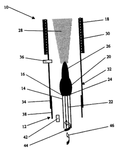
Referring first to Figure 1, there is shown an apparatus 10 for producing
single-wall carbon nanotubes, which comprises a plasma torch 12 having a
plasma tube 14 with a plasma-discharging end 16, and an oven 18 disposed
2o downstream of the plasma tube 14 in spaced relation thereto. The plasma
tube
14 is adapted to receive an inert gas for activation by electromagnetic
radiation
generated from a source (not shown) so as to form a primary plasma 20. A feed
conduit 22 having a discharge end 24 is arranged inside the plasma tube 14 and
extends coaxially thereof. The discharge end 24 of the feed conduit 22 is
disposed adjacent the plasma discharging end 16 of the plasma tube 14. The
feed conduit 22 serves to direct a carbon-containing substance, such as a
carbon-containing gas, and a metal catalyst towards the primary plasma 20 so
that the carbon-containing substance and the metal catalyst contact the
primary
plasma 20 at the plasma-discharging end 16 of the plasma tube 14, whereby to
form a secondary plasma 26 containing atoms or molecules of carbon and the
-10-
CA 02584508 2007-04-25
atoms of metal catalyst. The carbon-containing gas is preferably ethylene or
methane.
The oven 18 serves to condense the atoms or molecules of carbon and
atoms of metal catalyst to form single-wall carbon nanotubes 28. A heat source
30 is provided for heating the oven 18 to generate a temperature gradient
permitting gradual condensation of the atoms or molecules of carbon and the
atoms of metal catalyst. A heat-resistant tubular member 32 having a plasma-
receiving end 34 extends through the oven 18, the plasma-receiving end 34
io being disposed upstream of the plasma-discharging end 16 of the plasma tube
14. The apparatus further includes a gas injector 36 for injecting a cooling
inert
gas into the tubular member 32, downstream of the secondary plasma 26. The
cooling inert gas assists in providing the temperature gradient. Another heat-
resistant tubular member 38 is disposed about the plasma tube 14 and extends
coaxially thereof, the tubular member 38 being fixed to the tubular member 32
and supporting same. Another gas injector 42 is provided for injecting a
further
inert gas between the plasma tube 14 and the tubular member 38 to prevent
undesirable formation of carbon deposit adjacent the plasma-discharging end
16 of said plasma tube 14.
The inert gas flows through the plasma tube 14 along a helical path
represented by the arrow 44. Similarly, the carbon-containing gas and the
metal
catalyst, optionally in admixture with a carrier gas, flow through the feed
conduit 22 along a helical path represented by the arrow 46. The metal
catalyst
which is fed through the conduit 22 can be either an organometallic complex
such as ferrocene, or an inorganic metal catalyst such as iron. Instead of
feeding the metal catalyst through the conduit 22, it is possible to feed only
the
carbon-containing gas through the conduit 22 and to feed the metal catalyst in
admixture with the inert gas through the plasma tube 14. In such a case, the
metal catalyst must be an inorganic metal catalyst to prevent undesirable
-11-
CA 02584508 2007-04-25
formation of carbon deposit adjacent the plasma-discharging end 16 of the
plasma tube 14. It is also possible to feed the inert gas and an inorganic
metal
catalyst through the plasma tube 14 and to feed the carbon-containing gas in
admixture with an organometallic complex or an inorganic metal catalyst
through the conduit 22.
Figure 2 illustrates another apparatus 48 for producing single-wall
carbon nanotubes, which comprises a plasma torch 50 having a plasma tube 52
with a plasma-discharging end 54, and an oven 56 disposed downstream of the
io plasma tube 52 in spaced relation thereto. The plasma tube 52 is adapted to
receive an inert gas for activation by electromagnetic radiation generated
from
a source (not shown) so as to form a primary plasma 58. A feed conduit 60
having a discharge end 62 disposed adjacent the plasma-discharging end 54 of
the plasma tube 52 is provided for directing a carbon-containing substance,
such as a carbon-containing gas, and a metal catalyst towards the primary
plasma 58. The carbon-containing substance and the metal catalyst discharged
from the feed conduit 60 contact the primary plasma 58 at the plasma-
discharging end 54 of the plasma tube 52, thereby forming a secondary plasma
64 containing atoms or molecules of carbon and the atoms of metal catalyst.
2o The carbon-containing gas is preferably ethylene or methane. Although only
one feed conduit 60 is shown in Figure 2, it is possible to have a plurality
of
such conduits disposed symmetrically about the plasma tube 52.
The oven 56 serves to condense the atoms or molecules of carbon and
the atoms of metal catalyst to form single-wall carbon nanotubes 66. A heat
source 68 is provided for heating the oven 56 to generate a temperature
gradient permitting gradual condensation of the atoms or molecules of carbon
and the atoms of metal catalyst. A heat-resistant tubular member 70 having a
plasma-receiving end 72 extends through the oven 56, the plasma-receiving
3o end 72 being disposed upstream of the plasma-discharging end 54 of the
- 12-
CA 02584508 2007-04-25
plasma tube 52. The apparatus further includes a gas injector 74 for injecting
a
cooling inert gas into the tubular member 70, downstream of the secondary
plasma 64. The cooling inert gas assists in providing the temperature
gradient.
The inert gas flows through the plasma tube 52 along a helical path
represented by the arrow 76. Similarly, the carbon-containing gas and the
metal
catalyst, optionally in admixture with a carrier gas, flow through the conduit
60
along a helical path represented by the arrow 78. The metal catalyst which is
fed through the conduit 60 can be either an organometallic complex such as
i o ferrocene, or an inorganic metal catalyst such as iron. Instead of feeding
the
metal catalyst through the conduit 60, it is possible to feed only the carbon-
containing gas through the conduit 60 and to feed the metal catalyst in
admixture with the inert gas through the plasma tube 52. In such a case, the
metal catalyst must be an inorganic metal catalyst to prevent undesirable
formation of carbon deposit adjacent the plasma-discharging end 54 of the
plasma tube 52. It is also possible to feed the inert gas and an inorganic
metal
catalyst through the plasma tube 52 and to feed the carbon-containing gas in
admixture with an organometallic complex or an inorganic metal catalyst
through the conduit 60.
The apparatus 48' illustrated in Figure 3 is similar to the apparatus 48
shown in Figure 2, with the exception that an additional feed conduit 60' is
provided, the feed conduits 60 and 60' being arranged on either side of the
plasma tube 52. The conduit 60' has a discharge end 62' disposed adjacent the
plasma-discharging end 54 of the plasma tube 52 and serves the same purpose
as the feed conduit 60. The carbon-containing gas and the metal catalyst,
optionally in admixture with a carrier gas, flow through the conduit 60' along
a
helical path represented by the arrow 78'. Although two feed conduits 60 and
60' are shown in Figure 3, it is possible to have a plurality of such conduits
3o disposed symmetrically about the plasma tube 52. Instead of feeding the
metal
-13-
CA 02584508 2007-04-25
catalyst through the conduits 60 and 60', it is possible to feed only the
carbon-
containing gas through the conduits 60 and 60' and to feed the metal catalyst
in
admixture with the inert gas through the plasma tube 52. In such a case, the
metal catalyst must be an inorganic metal catalyst to prevent undesirable
s formation of carbon deposit adjacent the plasma-discharging end 54 of the
plasma tube 52. It is also possible to feed the inert gas and an inorganic
metal
catalyst through the plasma tube 52 and to feed the carbon-containing gas in
admixture with an organometallic complex or an inorganic metal catalyst
through the conduits 60 and 60'.
-14-