Note: Descriptions are shown in the official language in which they were submitted.
CA 02589047 2012-03-08
ADAPTIVE SCANNING OF MATERIALS
USING NUCLEAR RESONANCE FLUORESCENCE IMAGING
Background
This invention relates to nonintrusive scanning for materials (such as, for
example,
detection of explosives, nuclear materials, or contraband at airports,
seaports, or other
transportation terminals), and more particularly, to a method and apparatus
for adaptive
scanning using nuclear resonance fluorescence.
There are many requirements that scanning methods may desirably meet. First,
it
may be desirable that the measurements be reliable in detecting threats or
contraband with
a high probability of detection (DP) and a low probability of obtaining a
false positive (FP).
Further, it may be desirable that a scanning method operate as rapidly as
possible while
having a high rate of detection and a low rate of false positive events. Also,
the searches
may desirably be non-intrusive and non-destructive. Since the articles to be
examined may
be sizeable (such as shipping containers), the use of penetrating radiation is
attractive;
however, the radiation should preferably not leave the scanned article
radioactive. The
capability to image a target may also be of value. An adaptive method for
optimally
achieving these goals using Nuclear Resonance Fluorescence Imaging (NRFI) is
presented
here.
Summary
Disclosed herein are methods and apparatus for detecting one or more nuclear
species of interest in a target sample by adaptive scanning using nuclear
resonance
fluorescence. Also disclosed herein are methods and apparatus for adaptive
noninvasive
scanning of a target sample for detection of contraband, threats such as
explosives or
nuclear material, or other materials.
In one exemplary embodiment, a method for detecting a species in a target
sample,
may comprise illuminating the target sample with photons from a source;
detecting a signal
- 1 -
CA 02589047 2007-05-24
WO 2005/081017
PCT/US2004/039043
in at least one energy channel; determining a scan evaluation parameter using
the signal
detected in the at least one energy channel; determining whether the scan
evaluation
parameter meets a detection efficiency criterion; adjusting one or more system
parameters
such that the scan evaluation parameter meets the detection efficiency
criterion; and
comparing the signal in at least one energy channel to a predetermined species
detection
criterion to identify a species detection event. In another exemplary
embodiment,
determining the scan evaluation parameter using the detected signal may
further comprise
determining a background contribution to the signal in the at least one energy
channel. In
still another exemplary embodiment determining the scan evaluation parameter
using the
detected signal may further comprise determining the signal-to-noise ratio in
the at least
one energy channel. In still another exemplary embodiment, detecting a signal
in at least
one energy channel may further comprise detecting photons scattered from the
at least a
portion of the target sample in the at least one energy channel. In still
another exemplary
embodiment, detecting a signal in at least one energy channel may further
comprise
detecting photons transmitted through the target sample and scattered from at
least one
reference scatterer.
In another exemplary embodiment, a method for conducting a scan of a target
sample for a potential threat may comprise providing a source of photons
incident upon the
target sample; measuring an energy spectrum of photons scattered from the
target sample;
computing at least one scan evaluation parameter using the energy spectrum of
photons
scattered from the target sample; determining whether a threat has been
detected using the
measured energy spectrum of photons scattered from the target sample. If a
threat has been
detected, the method may further comprise determining whether the at least one
scan
evaluation parameter meets a detection efficiency criterion. If the scan
evaluation parameter
does not meet the detection efficiency criterion, the method may further
comprise adjusting
one or more system parameters and repeating the steps of measuring the energy
spectrum of
scattered photons, computing a scan evaluation parameter, determining whether
a threat has
been detected, and determining whether the scan evaluation parameter meets the
detection
efficiency criterion. If the at least one scan evaluation parameter meets the
detection
efficiency criterion, the method may further comprise identifying a positive
threat detection
event.
In still another exemplary embodiment, the scan evaluation parameter may
comprise
a detection probability and the detection efficiency criterion may comprise
the detection
- 2 -
CA 02589047 2007-05-24
WO 2005/081017 PCT/US2004/039043
probability exceeding a minimum desired detection probability. In still
another exemplary
embodiment, the scan evaluation parameter may comprise a probability of
obtaining a false
positive result, and the detection efficiency criterion may comprise the
probability of
obtaining a false positive result being less than a maximum desired
probability of obtaining
a false positive result. In still another exemplary embodiment, the scan
evaluation
parameter may comprise a detection probability and a probability of obtaining
a false
positive result, and the detection efficiency criterion may comprise the
detection probability
exceeding a minimum desired detection probability and the probability of
obtaining a false
positive result being less than a maximum desired probability of obtaining a
false positive
result.
In another exemplary embodiment, a method for conducting a scan of a target
sample for a potential threat may comprise providing a source of photons
incident upon the
target sample, such that at least some photons are transmitted through the
sample; allowing
at least some of the photons transmitted through the sample to scatter from at
least one
reference scatterer; measuring an energy spectrum of photons scattered from
the at least one
reference scatterer; computing at least one scan evaluation parameter using
the energy
spectrum of photons scattered from the at least one reference scatterer;
determining whether
a threat has been detected using the measured energy spectrum of photons
scattered from
the reference scatterer. If a threat has been detected, the method may further
comprise
determining whether the at least one scan evaluation parameter meets a
detection efficiency
criterion. If the at least one scan evaluation parameter does not meet the
detection
efficiency criterion, the method may further comprise adjusting one or more
system
parameters and repeating the steps of computing a scan evaluation parameter,
determining
whether a threat has been detected, and determining whether the scan
evaluation parameter
meets a detection efficiency criterion. If the at least one scan evaluation
parameter meets
the detection efficiency criterion, the method may further comprise
identifying a positive
threat detection event. In still another exemplary embodiment, the scan
evaluation
parameter may comprise a detection probability and the detection efficiency
criterion may
comprise the detection probability exceeding a minimum desired detection
probability. In
still another exemplary embodiment, the scan evaluation parameter may comprise
a
probability of obtaining a false positive result, and the detection efficiency
criterion may
comprise the probability of obtaining a false positive result being less than
a maximum
desired probability of obtaining a false positive result. In still another
exemplary
- 3 -
CA 02589047 2007-05-24
WO 2005/081017 PCT/US2004/039043
embodiment, the scan evaluation parameter may comprise a detection probability
and a
probability of obtaining a false positive result, and the detection efficiency
criterion may
comprise the detection probability exceeding a minimum desired detection
probability and
the probability of obtaining a false positive result being less than a maximum
desired
probability of obtaining a false positive result.
In another exemplary embodiment, a method for detecting a potential threat in
a
target sample may comprise providing a source of photons; illuminating the
target sample
with photons from the source; providing at least one photon detector to
measure an intensity
of photons scattered from at least a portion the target sample in at least one
energy channel;
determining a nominal background signal in each of the at least one energy
channels of
interest; computing a signal-to-noise ratio in each of the at least one energy
channels of
interest; adjusting one or more system parameters to improve the signal-
to-noise ratio
of the data collected in at least one of the at least one energy channels of
interest; and
identifying a threat detection event if the intensity of photons detected in
at least one of the
at least one energy channels of interest meets predetermined threat detection
criteria. In
further exemplary embodiments, the step of adjusting one or more system
parameters may
further comprise one or more of the following: altering an effective dwell
time of the
photons in a region of the target sample; inserting a filter into the source
of photons, the
filter comprising one or more nuclear species to absorb photons having
selected energies or
energy regions; where the photon source comprises a bremsstrahlung target
struck by a
beam of electrons, altering the energy of the electron beam; altering the
intensity and/or
collimation of the source of photons; altering the collimation of one or more
photon
detectors; inserting a filter in front of one or more photon detectors, the
filter comprising
one or more nuclear species to absorb photons having energies falling into
selected energy
regions; altering the angle at which one or more of the photon detectors views
the target
sample; and/or altering the spot area of the photon beam where it is incident
on the target
sample.
In another exemplary embodiment, a method for detecting a potential threat in
a
target sample may comprise providing a source of photons; illuminating the
target sample
with photons from the source; providing at least one photon detector to
measure an intensity
of photons scattered from at least a portion the target sample in at least one
energy channel;
providing a transmission detector for measuring an intensity of photons
transmitted through
the target sample as a function of a position on the target sample at which
the photons
- 4 -
CA 02589047 2007-05-24
WO 2005/081017 PCT/US2004/039043
illuminate the target sample; identifying at least one region of interest for
further scanning
using the intensity of photons transmitted through the target sample as a
function of a
position on the target sample at which the photons illuminate the target
sample; determining
a nominal background signal of photons scattered from at least one of the at
least one
regions of interest into each of the at least one energy channels of interest;
computing a
signal-to-noise ratio in each of the at least one energy channels of interest;
adjusting one or
more system parameters to improve the signal-to-noise ratio and/or the
statistical precision
in at least one of the at least one energy channels of interest; and
identifying a threat
detection event if the intensity of photons detected in at least one of the at
least one energy
channels of interest meets a predetermined threat detection criterion. In a
further exemplary
embodiment, the transmission detector may comprise an X-ray imager. In still
further
exemplary embodiments, the step of adjusting one or more system parameters may
further
comprise one or more of the following: altering an effective dwell time of the
photons in a
region of the target sample; inserting a filter into the source of photons,
the filter
comprising one or more nuclear species to absorb photons having selected
energies or
energy regions; where the photon source comprises a bremsstrahlung target
struck by a
beam of electrons, altering the energy of the electron beam; altering the
intensity and/or
collimation of the source of photons; altering the collimation of one or more
photon
detectors; inserting a filter in front of one or more photon detectors, the
filter comprising
one or more nuclear species to absorb photons having energies falling into
selected energy
regions; altering the angle at which one or more of the photon detectors views
the target
sample; and/or altering the spot area of the photon beam where it is incident
on the target
sample.
In another exemplary embodiment, a method for detecting a potential threat in
a
target sample may comprise providing a source of photons; illuminating the
target sample
with photons from the source; providing at least one reference scatterer, the
reference
scatterer comprising at least one nuclear species of interest; allowing
photons transmitted
through the target sample to scatter from the at least one reference
scatterer; providing at
least one photon detector to measure an intensity of photons scattered from
the at least one
reference scatterer in at least one energy channel; determining a nominal
background signal
in each of the at least one energy channels of interest; computing a signal-to-
noise ratio in
each of the at least one energy channels of interest; adjusting one or more
system
parameters to improve the signal-to-noise ratio in at least one of the at
least one energy
- 5 -
CA 02589047 2007-05-24
WO 2005/081017
PCT/US2004/039043
channels of interest; and identifying a threat detection event if the
intensity of photons
detected in at least one of the at least one energy channels of interest meets
a predetermined
threat detection criterion. In further exemplary embodiments, the step of
adjusting one or
more system parameters may further comprise one or more of the following:
altering an
effective dwell time of the photons in a region of the target sample;
inserting a filter into the
source of photons, the filter comprising one or more nuclear species to absorb
photons
having selected energies or energy regions; where the photon source comprises
a
bremsstrahlung target struck by a beam of electrons, altering the energy of
the electron
beam; altering the intensity and/or collimation of the source of photons;
altering the
collimation of one or more photon detectors; inserting a filter in front of
one or more
photon detectors, the filter comprising one or more nuclear species to absorb
photons
having energies falling into selecte,d energy regions; altering the angle at
which one or more
of the photon detectors views the target sample; and/or altering the spot area
of the photon
beam where it is incident on the target sample.
In another exemplary embodiment, a method for detecting a potential threat in
a
target sample may comprise providing a source of photons; illuminating the
target sample
with photons from the source; providing a transmission detector for measuring
an intensity
of photons transmitted through the target sample as a function of a position
on the target
sample at which the photons illuminate the target sample; identifying at least
one region of
interest for further scanning using the intensity of photons transmitted
through the target
sample as a function of a position on the target sample at which the photons
illuminate the
target sample; providing at least one reference scatterer, the reference
scatterer comprising
at least one nuclear species of interest; allowing photons transmitted through
the at least one
region of interest of the target sample to scatter from the at least one
reference scatterer;
providing at least one photon detector to measure an intensity of photons
scattered from the
at least one reference scatterer in at least one energy channel; determining a
nominal
background signal in each of the at least one energy channels of interest;
computing a
signal-to-noise ratio in each of the at least one energy channels of interest;
adjusting one or
more system parameters to improve the signal-to-noise ratio in at least one of
the at least
one energy channels of interest; and identifying a threat detection event if
the intensity of
photons detected in at least one of the at least one energy channels of
interest meets a
predetermined threat detection criterion. In a further exemplary embodiment,
the
transmission detector may comprise an X-ray imager. In still further exemplary
- 6 -
CA 02589047 2007-05-24
WO 2005/081017 PCT/US2004/039043
embodiments, the step of adjusting one or more system parameters may further
comprise
one or more of the following: altering an effective dwell time of the photons
in a region of
the target sample; inserting a filter into the source of photons, the filter
comprising one or
more nuclear species to absorb photons having selected energies or energy
regions; where
the photon source comprises a bremsstrahlung target struck by a beam of
electrons, altering
the energy of the electron beam; altering the intensity and/or collimation of
the source of
photons; altering the collimation of one or more photon detectors; inserting a
filter in front
of one or more photon detectors, the filter comprising one or more nuclear
species to absorb
photons having energies falling into selected energy regions; altering the
angle at which one
or more of the photon detectors views the target sample; and/or altering the
spot area of the
photon beam where it is incident on the target sample.
In another exemplary embodiment, a method for detecting a potential threat in
a
target sample may comprise providing a source of photons; illuminating the
target sample
with photons from the source; providing at least one reference scatterer, the
reference
scatterer comprising at least one nuclear species of interest; allowing
photons transmitted
through the target sample to scatter from the at least one reference
scatterer; providing at
least one reference-photon detector to measure an intensity of photons
scattered from the at
least one reference scatterer in at least one reference-photon energy channel
as a function of
a position on the target sample at which the photons illuminate the target
sample; using the
intensity of photons measured by the reference-photon detector in each of the
at least one
reference-photon energy channels of interest to identify at least one region
of interest for
further scanning; providing at least one scattered-photon detector to measure
an intensity of
photons scattered from a region of interest in the target sample in at least
one scattered-
photon energy channel; determining a nominal background signal of photons
measured by
the at least one scattered-photon detector in each of the at least one
scattered-photon energy
channels of interest; computing a signal-to-noise ratio in each of the at
least one scattered-
photon energy channels of interest; adjusting one or more system parameters to
improve the
signal-to-noise ratio and/or the statistical precision in at least one of the
at least one
scattered-photon energy channels of interest; and identifying a threat
detection event if the
intensity of photons detected in at least one of the at least one scattered-
photon energy
channels of interest meets a predetermined threat detection criterion. In
further exemplary
embodiments, the step of adjusting one or more system parameters may further
comprise
one or more of the following: altering an effective dwell time of the photons
in a region of
- 7 -
CA 02589047 2007-05-24
WO 2005/081017 PCT/US2004/039043
the target sample; inserting a filter into the source of photons, the filter
comprising one or
more nuclear species to absorb photons having selected energies or energy
regions; where
the photon source comprises a bremsstrahlung target struck by a beam of
electrons, altering
the energy of the electron beam; altering the intensity and/or collimation of
the source of
photons; altering the collimation of one or more photon detectors; inserting a
filter in front
of one or more photon detectors, the filter comprising one or more nuclear
species to absorb
photons having energies falling into selected energy regions; altering the
angle at which one
or more of the photon detectors views the target sample; and/or altering the
spot area of the
photon beam where it is incident on the target sample.
In another exemplary embodiment, a method for conducting a scan of a target
sample for a potential threat may comprise providing a source of photons
incident upon the
target sample such that some photons are scattered from the sample and some
photons are
transmitted through the sample; measuring an intensity of photons transmitted
through at
least a portion of the target sample; and using the measured intensity of
photons transmitted
through the at least a portion of the target sample to identify at least one
region of interest
for further study. In a further embodiment, the method may further comprise
undertaking
the following steps for at least one of the identified regions of interest:
measuring an energy
spectrum of photons scattered from the region of interest; using the energy
spectrum of
photons scattered from the region of interest to compute a detection
probability and a
probability of obtaining a false positive result; and using the measured
energy spectrum of
photons scattered from the region of interest to determine whether a threat
has been
detected. If a threat has not been detected, the method may further comprise
determining
whether the detection probability meets or exceeds a predetermined desired
detection
probability. If the detection probability meets or exceeds the predetermined
desired
detection probability, the method may further comprise ending the scan for the
region of
interest. If the detection probability does not meet or exceed the
predetermined desired
detection probability, the method may further comprise adjusting one or more
system
parameters and repeating the steps of measuring an energy spectrum of photons
scattered
from the region of interest; using the energy spectrum of photons scattered
from the region
of interest to compute a detection probability and a probability of obtaining
a false positive
result; and using the measured energy spectrum of photons scattered from the
region of
interest to determine whether a threat has been detected. If a threat has been
detected, the
method may further comprise determining whether the probability that the
threat detection
- 8 -
CA 02589047 2007-05-24
WO 2005/081017 PCT/US2004/039043
is a false positive signal exceeds a predetermined desired probability of
obtaining a false
positive result. If the probability that the threat detection is a false
positive signal meets or
exceeds the predetermined desired probability of obtaining a false positive
result, the
method may further comprise adjusting one or more system parameters and
repeating the
steps of measuring an energy spectrum of photons scattered from the region of
interest;
using the energy spectrum of photons scattered from the region of interest to
compute a
detection probability and a probability of obtaining a false positive result;
and using the
measured energy spectrum of photons scattered from the region of interest to
determine
whether a threat has been detected. If the probability that the threat
detection is a false
positive signal does not meet or exceed the predetermined desired probability
of obtaining a
false positive result, the method may further comprise identifying a positive
threat detection
event.
Brief Description of the Drawings
These and other features and advantages of the method of adaptive scanning of
materials using nuclear resonance fluorescence disclosed herein will be more
fully
understood by reference to the following detailed description, in conjunction
with the
attached drawings. The drawings illustrate principles of the apparatus
disclosed herein, and
are not to scale.
Figure 1 is a schematic illustration of an embodiment of a system that may be
used
for adaptive scanning of materials using nuclear resonance fluorescence;
Figure 2 illustrates NRF spectra of 48Ti and 27A1 made with bremsstrahlung
photon
beams generated with electron beams at 4.1 MeV and 11 MeV;
Figure 3 illustrates NRF spectra of 209Bi and 208Pb made with bremsstrahlung
photon beams generated with electron beams at 2.72 MeV; and
Figure 4 illustrates typical Receiver Operator Characteristic (ROC) curves for
three
signal-to-noise ratios, calculated for a signal of 30 counts (Figure 4a) and a
signal of 42
counts (Figure 4b); and
Figure 5 is a flow chart illustrating an exemplary embodiment of an adaptive
scanning method.
- 9 -
CA 02589047 2012-03-08
Detailed Description of Exemplary Embodiments
To provide an overall understanding, certain illustrative embodiments will now
be
described; however, it will be understood by one of ordinary skill in the art
that the devices
and methods described herein can be adapted and modified to provide devices
and methods
for other suitable applications and that other additions and modifications can
be made
without departing from the scope of the systems described herein.
Unless otherwise specified, the illustrated embodiments can be understood as
providing exemplary features of varying detail of certain embodiments, and
therefore,
unless otherwise specified, features, components, modules, and/or aspects of
the
illustrations can be otherwise combined, specified, interchanged, and/or
rearranged without
departing from the disclosed devices or methods. Additionally, the shapes and
sizes of
components are also exemplary, and unless otherwise specified, can be altered
without
affecting the disclosed devices or methods.
A beam of photons having a continuous energy spectrum incident on a target can
excite nuclear resonances or states in the target which subsequently
fluoresce. The
resulting emission spectra are uniquely tied to the specific isotopes
contained in the target.
When detected by systems of detectors or detector arrays capable of resolving
spatial
information, these spectra allow for a measurement of the spatial distribution
of isotopes
contained in the irradiated volume.
Some exemplary systems for employing resonant scattering measurements (also
called nuclear resonance fluorescence or NRF) in nonintrusive scanning
applications are
discussed in U. S. Patent No. 5,115, 459, Explosives Detection Using Resonance
Fluorescence of Bremsstrahlung Radiation, and U. S. Patent No. 5,420, 905,
Detection of
Explosives and Other Materials Using Resonance Fluorescence, Resonance
Absorption,
and Other Electromagnetic Processes with Bremsstrahlung Radiation.
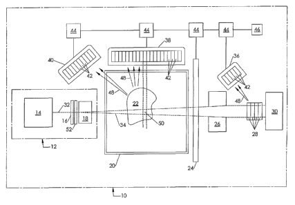
A schematic diagram of an exemplary embodiment of a nuclear resonance
fluorescence imaging (NRF1) scanner configuration is shown in Figure 1.
The system includes a photon source 12 producing photons having an energy
spectrum over some energy range. Suitable photon sources include: a
bremsstrahlung
source; a Compton-broadened photon source using nuclear decay from a
radioactive
source; coherent bremsstrahlung radiation; free electron lasers; laser
backscatter from high
energy electrons; or other photon sources known to those skilled in the field.
- 10-
CA 02589047 2007-05-24
WO 2005/081017 PCT/US2004/039043
=
In the illustrated embodiment, the photon source 12 is a bremsstrahlung source
and
may include an electron source 14 providing a beam of electrons 32 incident on
a
bremsstrahlung target 16 to generate a bremsstrahlung photon beam 34. The
bremsstrahlung target 16 may be followed by a beam stopper (not illustrated)
to stop the
electrons 32. A filter 52 may follow the beam stopper, for example to filter
out low energy
photons from the bremsstrahlung beam 34, or to preferentially absorb photons
in energy
regions corresponding to particular NRF lines. A collimator 18 may be employed
to
collimate the bremsstrahlung beam 32. Shielding (not illustrated) may enclose
the photon
source 12. A description of an exemplary suitable bremsstrahlung photon source
may be
found in United States Patent No. 5,115,459.
A target 20 to be scanned, such as a cargo container, shipping container,
luggage,
package, or other container or object, may be placed in the path of the
bremsstrahlung
beam 34. In one embodiment, the target may be moved through the path of the
beam, for
example by a conveyor belt. In another embodiment, the beam 34 may be scanned
across
the target 20, for example, by moving photon source 12 or steering the
electron beam 32.
The target 20 may contain target contents 22. Other ways of achieving scanning
of the
photon beam 34 over the target container 20 will be rocognized by those
skilled in the art.
The incident photon beam 34 resonantly excites the nuclei of the target's
contents 22, and
photons 48 may be both scattered from the contents 22 and the target 20 as
well as
transmitted through the contents 22 and the target 20. The energies of the
scattered photons
are characteristic of the spacings between the quantized energy states of the
nuclei of the
target contents 22 and the target 20. Each isotope present in the target
contents 22
resonantly scatters photons in a unique set of energies.
Detecting apparatuses 38 and 40, which may include an array of detectors 42,
may
capture, measure, count, and/or record the energies of the photons scattered
in a given
direction or directions. A description of several exemplary suitable detecting
apparatuses
may be found in United States Patent No. 5,115,459. The detecting apparatus 38
or 40 may
further include a filter over the face of each detector to absorb low energy
photons, and
shielding (not illustrated). As scattering from the collimating aperture 18
could lead to a
significant amount of photons directed toward the detecting apparatus 38 or
40, a shadow
shield (not illustrated) between the collimator and the detecting apparatus 38
or 40 may be
employed. A beam dump 30 may be provided to absorb the energy of the beam 34
that is
not absorbed as the beam 34 passes through the target 20. Shielding (not
shown) may
-11 -
CA 02589047 2007-05-24
WO 2005/081017 PCT/US2004/039043
enclose the entire device while allowing convenient means for the entry and
exit of targets.
Data from the detecting apparatus 38 or 40 is sent to a processor 46 which may
analyze the
data. The processor 46 may comprise a PC, microcomputer, or other suitable
processor.
One analysis may include determining the abundances of particular nuclear
species of
interest. The data may be preprocessed by preprocessing electronics 44, which
may include
preamplifiers filters, timing electronics, or other appropriate preprocessing
electronics. The
processor 46 may be adapted to evaluate the data to determine whether the
contents of the
target volume meet or exceed one or more predetermined detection thresholds.
For
example, the processor 46 may compare the data for each irradiated target
volume to
profiles of "normal" target volumes to determine whether the irradiated target
volume
should be considered "suspicious." In addition, the processor 46 may be
programmed with
other threat detection heuristics as described below. Further, as described in
more detail
below, the processor 46 may control a variety of parameters of the photon
beam, scanning,
detection, and/or other aspects of the system.
In order to minimize the effects of Compton scattering and other scattering
processes and maximize the signal-to-noise ratio, the detecting apparatus 38
or 40 may be
placed at an angle with respect to the bremsstrahlung beam 34 of more than 90
degrees
relative to the direction of the photon beam, preferably substantially more
than 90 degrees.
The beam 34 'passes through the target contents 22. This beam may be absorbed
in
a beam dump 30 designed to absorb substantially all of the remaining energy.
For example,
a suitable beam dump for 10 MeV may include a layer of a hydrogenous material
containing boron or lithium, a layer of carbon, and a layer of iron in a very
deep cavity
formed in a shield of lead and/or iron to shield the sides and the detectors
from back-
streaming low energy photons. A layer of a hydrogenous material containing
boron or
lithium may surround the outside of this shield. The depth of this cavity, the
beam
dimensions, the directive collimation of the detectors, and the exact location
of the
detectors are related parameters that may be made compatible so as to minimize
the number
of backward-streaming photons from the beam dump entering the detectors.
Additional
shadow shields may be set up to help meet this goal.
Imaging can be achieved in a variety of ways with the technique of the present
invention. The luggage can be scanned with the beam by moving the entire
photon
source 12, the target 20, or simply the aperture 18. The electron beam may
also be
deflected by a magnet to sweep the bremsstrahlung beam direction. Preferred
photon beam
- 12,-
CA 02589047 2007-05-24
WO 2005/081017 PCT/US2004/039043
geometries include spots (cones) and stripes. Other suitable scanning
configurations,
geometrics, and patterns may be recognized by those skilled in the art and may
be
employed.
For example, if the beam 34 is collimated using a small circular aperture 18
to an
average angle of approximately 1/20 radians (about 3 degrees), the spot 1
meter from the
aperture will be about 10 cm across, a suitable size for imaging the contents
of a piece of
luggage or the contents 22 of a container 20.
If the photon beam 34 is collimated using a vertical slit aperture to produce
a thin
stripe of 10 cm width at the point of incidence with a piece of luggage, for
example, a
60 cm long suitcase could be scanned in a few seconds as the suitcase moves on
a conveyor
belt. Alternatively, the beam 34 could be collimated into a spot swept
vertically by an
adjustable collimator or by magnetic deflection of the electron beam 32 used
to generate the
photon beam 34. Even if the collimation is in the form of a vertical stripe,
the central
intensity remains the highest, reflecting the natural collimation, and
magnetic deflection of
the electron beam 32 may be useful for imaging. If the collimation is a
vertical stripe or a
stripe of another orientation, the intersections of the stripe with the
collimated views of the
detectors 42 define voxels that are also useful for imaging.
In another technique, a large portion of the target container 20 may be
flooded with
bremsstrahlung radiation by using a large aperture, and the detectors 42 may
be adapted to
be direction-specific by, for example, introducing a collimator in front of
each detector 42.
In this way, each detector can be designed to only detect photons scattered
from a small
specific region 50 of the target contents 22 in a particular direction. Each
such specific
region or "voxel" 50 may be conceptualized as the three dimensional
intersection of the
photon beam 34 with the line of sight of a collimated detector 42. An array of
such
detectors can be designed to image the entire target 20 to a desired degree of
resolution.
Alternative detection systems adapted for obtaining spatially resolved images
of
target contents will be recognized by persons of skill in the art. Such
detection systems
may include, for example, detector arrays equipped with coded aperture systems
that enable
two-dimensional or three-dimensional spatial information to be resolved.
Imaging
techniques such as those employed in processor 46 tomography (CT) may also be
employed
to obtain two- or three-dimensional images of the target 20 and its contents
22.
A combination of the above imaging techniques results in a further embodiment
of
the present invention. For example, a thin slit aperture could be used to
irradiate thin
- 13 -
CA 02589047 2007-05-24
WO 2005/081017 PCT/US2004/039043
vertical strips of the target 20 as the target 20 moves on a conveyor belt.
The width of the
strip will determine the horizontal resolution of the imaging. The vertical
resolution could
be increased by using directional detectors aimed at intervals along the
vertical height of the
illuminated area. Such a method would result in fast measurements at a high
resolution.
Use of a rapidly adjustable photon beam collimating aperture 18 results in
further
embodiments with important advantages. For example, a target 20 could first be
flooded
with bremsstrahlung radiation in an effort to detect explosives in the form of
thin sheets
and/or to obtain an initial estimate of the abundances of various elements in
its contents.
The collimating aperture 18 could then be stopped down to image the suitcase
in an effort
to detect more localized explosive materials. In one embodiment, the processor
46 may
control the size of the collimating aperture 18 in response to any positive
signal detected in
an initial low-resolution scan, as will be discussed further below.
The processor 46 may be adapted to analyze the data obtained by the detecting
apparatus in any combination of 38 and/or 40. As with other explosives
detecting devices,
profiles of elements, such as nitrogen and oxygen, as they appear in "normal"
target
volumes or voxels may either be modeled or experimentally determined. A target
volume
or voxel 50 or a combination of volumes or voxels 50 which deviates
significantly from
these profiles may be identified as "suspicious." The processor 46 can be
adapted to
compare data to stored profiles. If the profiles are rigorously determined, a
high probability
of explosives detection ("detection probability" or "DP") accompanied by a low
rate of
false alarms ("false positives" or "FP") may be achieved. If a region of a
target shows the
explicit elemental profile of an explosive the threat identification may be
determined.
The detection methods thus described, in which resonant scattering from the
target 20 and target contents 22 is detected by detectors 40, may be employed
to obtain
three-dimensional NRF imaging of the target contents 22. For example, if each
detector 40
is adapted to be directional (as by collimation, for example), then the NRF
spectrum
detected in each detector provides a measure of the isotopes contained in each
voxel 50
where the field of view of each detector 40 intersects the photon beam 34.
These spectra
may, if desired, be reconstructed as a 3-D isotopic image of the target
contents 22. For that
reason, the detection methods described above may be referred to as 3-D NRF
imaging.
To extract information about the abundance of each species identified in the
NRF
spectrum, it is necessary for the system to first obtain an approximation of
the photon flux
incident upon each voxel 50. In one embodiment this may be achieved by
observing the
- 14 -
CA 02589047 2007-05-24
WO 2005/081017 PCT/US2004/039043
scattered photon spectra from each voxel 50 along the path of the photon beam
34 and,
using the observed spectra to compute an average attenuation of the beam 34 in
each voxel
50, and adjusting the estimated incident flux on each successive voxel 50
based upon the
attenuation in each of the previous voxels. Thus, in an exemplary embodiment,
the incident
flux on the first voxel 50 where the beam 34 initially strikes the target 20
is known. The
spectrum of photons scattered from the first voxel may then be fit. In one
embodiment, the
fit may be a complete model that includes contributions such as the resonant
scattering
peaks plus background due to Compton scattering, pair production, and
photoelectric
effects in the detector and nonresonant background contributions. The isotopic
composition
of the first voxel may be extracted from the result of that fit, using such
information as the
known incident flux on the first voxel, the known interaction cross sections
for the observed
NRF resonances, the known detector efficiencies, etc. From the measured
spectrum and/or
from the measured isotopic composition of the first voxel, the attenuation of
the photon
beam 34 as it passes through that first voxel may be determined and used to
compute an
estimate of the incident flux on the second voxel. The fitting process may
then be repeated
for the second voxel, and the incident flux for the next subsequent voxel
determined from
the attenuation the second voxel, and so on along the path of the photon beam
34 through
the target 20. In some embodiments, the incident photon flux on each voxel
along the beam
may be determined as a function of energy using known absorption
characteristics and
measured abundances of the isotopes identified in the previous voxels along
the photon
beam 34. As will be discussed further below, these computed incident photon
fluxes may
be used in computing a minimum number of photons scattered in a particular
energy
channel from a particular voxel that will be considered a threat. This
procedure may be
iterated and further constrained by, for example, measuring the total
transmitted flux and
incorporating that information into the fit to the complete energy spectrum
from each voxel
50.
An alternate detecting scheme is also illustrated in Figure 1. This alternate
scheme
can provide a 2-D NRF image of the isotopic composition of the target contents
22. As the
photon beam 34 passes through the target 20, photons will be resonantly
absorbed by the
nuclei of the target contents 22. The energies of the absorbed photons
correspond to the
spacings between the quantized energy states of each nuclear species in the
target 20. For
these specific energies, the transmitted beam will be depleted of photons. For
example, if
the target contains nitrogen, photons of energies corresponding to the
spacings between
- 15 -
CA 02589047 2007-05-24
WO 2005/081017 PCT/US2004/039043
nuclear energy states in nitrogen will be selectively absorbed. The amount of
photons
absorbed depends on the quantity of nitrogen in the target 20. Thus, the
intensities of the
photons of specific energies transmitted through the target contain
information about the
nuclear composition of the target. A series of reference resonance scatterers
28 may be
arranged behind the target 20. Each reference scatterer 28 may be composed of
one or
more of the elements that the explosives detecting device is to detect. An
array 36 of
detecting apparatuses 42 may be adapted to capture, measure, count, and record
the
photons 48 resonantly scattered from each of the reference scatterers 28. For
example, in a
simple embodiment, two reference scatterers are provided, one of nitrogen, the
other of
oxygen. In such an embodiment, a detecting apparatus may be adapted to detect
photons
resonantly scattered from the nuclei in the nitrogen scatterer and another
detecting
apparatus may be adapted to detect photons resonantly scattered from the
nuclei in the
oxygen scatterer. Alternatively, a single detecting apparatus 42 may be
adapted to detect
photons resonantly scattered from nuclei in all the reference scatterers 28.
This detecting scheme operates as follows. If no target 20 is placed in the
path of
the beam 34, the photon beam will directly strike the first of the reference
resonance
scatterers 28. The detecting apparatus 36 associated with the first reference
scatterer will
detect a relatively large amount of photons corresponding to a nuclear species
contained in
the first reference scatterer, because there will have been essentially no
absorption at
energies corresponding to such a species. Likewise, if a target 20 containing
only a
relatively small amount of a nuclear species contained in the first reference
scatterer is
placed in the path of the beam, this strong signal at the first detecting
apparatus will be
diminished by only a relatively small amount. If however, a target 20 with a
relatively
large amount of the nuclear species contained in the first reference scatterer
is placed in the
path of the beam, this signal will be diminished considerably, due to the
resonant absorption
in the target 20 of the photons of energies corresponding to that nuclear
species.
Thus, an abundance of a nuclear species of interest in a target 20 and its
contents 22
will be detected as a decrease in the signal from the detecting apparatus
associated with a
reference scatterer containing that nuclear species. Photons of energies not
corresponding
to the nuclear species of which a reference scatterer is substantially
composed will be
attenuated due to non-resonant processes by only a relatively small amount.
Thus, the
method of detecting the nuclear species of the first reference scatterer
extends to each
subsequent reference scatterer. An advantage of this detecting scheme is that
if the energies
- 16 -
CA 02589047 2007-05-24
WO 2005/081017 PCT/US2004/039043
corresponding to two or more nuclear species of interest are very close, the
detecting
apparatus 38 or 40, detecting directly scattered photons, may have difficulty
distinguishing
the contributions from the two or more nuclear species. However, using the
transmitted
photons and reference scatterer 28, the energies corresponding to each nuclear
species are
detected separately, this ambiguity is diminished considerably, and the
ability of the
detecting apparatus to resolve closely spaced photon energies is no longer
very important.
When the energies corresponding to two or more nuclear species do not
interfere, a single
reference scatterer can be composed of a combination of the species.
It is a further advantage of this detection scheme that it may allow the total
amount
of material of a nuclear species corresponding to a nuclear species contained
in a reference
target to be measured quickly and with a relatively small number of detectors.
This may
allow, for example, a rapid first-pass scan of the target 20 for the presence
of any amount of
one or more nuclear species of interest, before a more detailed scan or
imaging procedure is
undertaken. Where such a rapid first-pass scan shows that no threatening
quantities of
nuclear species of interest are present, more detailed scans may be bypassed,
for a savings
of time and resources.
In the embodiment illustrated in Figure 1, the system may also include a
direct
transmission detector 24, such as an X-ray imager, which can measure the
intensity and/or
energy of photons transmitted through the target 20 as a function of the
lateral position in
which the photon beam strikes the target. Such a measurement could be used,
for example,
to obtain a map of the average density of the target 20, projected along the
axis of the
photon beam 34. In this way, a very precise image of the transmission density
of the target
can be constructed. Such an image will identify specific areas of high
material density in
the target which would be a further aid in detecting explosive or high atomic
number
materials. (Similar density imaging could also be achieved by detecting the
back-scatter
from the target 20, especially at low energies).
A direct transmission detector 24 or the 2-D NRF detection scheme described
above
in which photons transmitted through the target 20 are allowed to scatter from
reference
scatterers 28 may also provide an estimate of the total attenuation of the
photon beam 34 as
it passes through the target 20. In some embodiments, the total attenuation of
the photon
beam 34 may be used as a check of (or to provide a means for iteratively
correcting) the
determination described above of the photon flux entering each voxel along the
beam, as
noted previously.
- 17 -
CA 02589047 2007-05-24
WO 2005/081017 PCT/US2004/039043
Using NRF to Identify the Presence of Nuclear Species of Interest
The usefulness of Nuclear Resonance Fluorescence to identify nuclear species
present in a target or to detect species of interest is illustrated in Figure
2. Nuclear
Resonance Fluorescence spectra for the isotopes 48Ti and 27A1 (present in the
4.1 MeV
spectrum only) obtained from a bremsstrahlung beam produced by electron beams
with 4.1
and 11 MeV end-point energies are displayed in Figure 2. (These spectra are
described in
Degener, et al, Nuclear Physics A513 (1990) 29-42, the contents of which are
hereby
incorporated by reference.) The spectra were measured using a collimated high
energy
resolution germanium detector at angles greater than 90 degrees with respect
to the beam
direction. The narrow peaks (having a width of approximately 4 keV, limited by
detector
resolution) of the measured NRF states for 48Ti and 27A1 are easily detected
against the
continuous and slowly varying non-resonant background. The continuous
background
resulting from non-resonant background processes is observably higher for the
higher end-
point energy when looking at states of a fixed energy.
The characteristics of the energy spectra from non-resonant processes such as
Compton scattering and pair production, also directly provide information on
the density
and average atomic number (Z) of the volume under inspection. This is
illustrated in
Figure 3, in which the NRF spectrum for a 209Bi target are superimposed with
that of 208Pb
under identical experimental conditions. (These spectra are described in F.R.
Metzger,
Physical Review 187, pg. 1680 (1969), the contents of which are hereby
incorporated by
reference.) The 209Bi spectrum (solid curve) shows the presence of two strong
NRF states
(the third peak is from a contaminant in the target) while the 208Pb spectrum
(dashed curve)
has a smooth continuous background since this isotope does not have any NRF
states in this
energy region. The Z of 208Pb and 209Bi are 82 and 83, respectively, and as
expected from
theory and borne out in these measurements, the non-resonant background
processes are
essentially identical.
These spectra and the similar spectra obtained in other known NRF experiments
illustrate a number of points:
= The use of high energy-resolution detectors allows the straightforward
extraction of the intensity of NRF states in the presence of a non-resonant
background and hence the quantity of material in the region being probed
associated with each isotope for which an NRF state is excited.
- 18 -
CA 02589047 2007-05-24
WO 2005/081017 PCT/US2004/039043
= The non-resonant background is dependent on the atomic number (Z),
density
and amount of the target sample, in a way which can be measured or modeled.
= The non-resonant background underlying an NRF state is a function of the
bremsstrahlung beam end-point energy, and the Z of the target material.
The method proposed here may also incorporate a two-dimensional transmission
detector 24 such as an X-ray imager that may sample the integrated attenuation
with
relatively high spatial resolution. This complementary detector enables the
detection of
small dense objects. It can be used in connection with the NRF 3-D image
and/or the NRF
2-D transmission detector to dynamically identify regions of interest for
further scanning as
part of the adaptive system or for other purposes.
The signal to noise ratio for the measurement of a given NRF state relative to
the
non-resonant background may be determined by the phenomenon described above.
The
properties of the NRF states, including the scattering cross sections as a
function of energy
and angle for each nuclear species of interest, may be known prior to
scanning. The
number of photons scattered from a target voxel 50 and detected at a
particular scattering
angle at the characteristic energy or energies of the NRF state(s) associated
with a particular
nuclear species of interest are proportional to the abundance of that species
in the target
voxel. Measurements of the number of counts in an energy channel corresponding
to a
given NRF state and an estimate of the contribution of background non-resonant
processes
to the counts in that energy channel (such as the average background counts
due to non-
resonant processes in neighboring energy intervals, or other estimates of the
expected
background) can be used to estimate adaptively the detection probability (DP)
and the
probability of obtaining a false positive result (FP) for a given quantity of
a specified
isotope in the region of space being examined. This information can be used to
modify the
parameters of the scan so as to satisfy desired criteria for DP and FP. In
some
embodiments, measurement of the number of counts in an energy channel of
interest
together with an estimate of the contribution of the non-resonant background
to that number
of counts can provide a dynamic evaluation of the signal-to-noise ratio which
can be used
to adaptively modify scan parameters to satisfy desired DP and FP criteria.
For example, if
the region under examination has a relatively high non-resonant background,
the signal-to-
noise ratio will be lower and the dwell time of the bremsstrahlung beam can be
increased to
compensate by collecting more photon events in order to achieve higher
statistical
- 19 -
CA 02589047 2007-05-24
WO 2005/081017 PCT/US2004/039043
accuracy, or other system parameters may be adjusted to improve signal-to-
noise or
statistical accuracy as discussed in more detail below.
Although the following discussion of an exemplary method of adaptive scanning
uses a dynamic determination of the signal-to-noise ratio to determine whether
desired DP
and FP criteria are achieved, it will be understood by those skilled in the
art that the
measurement of the number of counts in the energy channel or channels of
interest and the
measured, estimated, or approximated background, particularly as a function of
energy,
may be considered independently in determining DP and FP. For example, in
cases where
there is no appreciable background in an energy channel or energy region of
interest, all
counts in that channel or region may be attributable to the presence of an
isotope
corresponding to that channel or region, and a determination of whether a
threshold
quantity of that isotope exists may be made without the step of determining
the signal-to-
noise ratio.)
Example of the Adaptive Scanning Method
An exemplary embodiment of a method of adaptive scanning of a target to
identify
threshold quantities of nuclear species of interest will now be described. In
the
embodiment described, threshold quantities of nuclear species of interest may
be described
as "threats," and an aim of the method may be adaptive scanning of cargo
containers,
luggage, or other targets to detect the presence of threats such as nuclear
material or
conventional explosives. However, it will be understood by persons of skill in
the art that
the methods disclosed herein may be applied to any application in which
nonintrusive
scanning of a target to identify the isotopic composition of the target or to
detect threshold
quantities of particular species of interest is desired. Such applications may
include
(without limitation) scanning cargo containers to determine whether their
contents match
the associated shipping manifests, and/or identifying the presence of toxic
substances such
as Sarin, Phosgene, or other agents, in addition to scanning targets for the
presence of
nuclear materials, quantities of high-density materials (which may indicate
shielded nuclear
or other materials), explosives, or contraband.
In one embodiment, an initial flux of photons may be injected into a voxel 50
in the
target 20, and the spectrum of photons detected at the corresponding detector
42 may be
analyzed by fitting to a curve that accounts for the non-resonant background
and the
contributions from any resonance peaks that may be present. The processor 46
may also
-20 -
CA 02589047 2007-05-24
WO 2005/081017 PCT/US2004/039043
collect the number of counts in an energy channel or energy channels of
interest that.
correspond to energy level spacings in nuclear species of interest.
The processor 46 may use this initial observation to make a first
approximation of
the background in each energy channel of interest. In one embodiment, a first
approximation to the background (i.e., non-resonant) contribution to the
signal detected in
an energy channel corresponding to a nuclear resonance transition in a species
of interest
may be obtained by averaging the number of counts detected in the adjacent
channels if
they do not occur at the energy of an NRF line. The background may also be
estimated by,
for example, a 1/E distribution, in particular a 1/E distribution fit locally
to the energy
region of interest. Corrections to the estimated background may be applied.
For example,
for every resonant photopeak detected in a detector, there will also be known,
non-resonant,
lower energy scattered photons associated with that resonant signal. Thus, the
estimated
background may be corrected by subtracting any resonant and non-resonant
signal detected
that is known or recognized to correspond to any particular nuclear species.
The estimated
background may take into account the attenuation of the photon beam as it
passes through
and interacts with the target contents 22 on its way to the voxel 50 under
observation. In
one embodiment, this attenuation may be measured by direct scattering
measurements in
detectors arrays 38 or 40, or by estimates of the average density of the
target 20 obtained
from weighing the target 20, referring to a cargo manifest, or measuring the
intensity of
transmitted photons using apparatus such as x-ray imager 24 or transmission
detectors 36
with reference scatterers 28.
The processor 46 may use the estimated background together with other
parameters
to generate a threshold threat signal for each nuclear species of interest.
Such a threshold
threat signal could be a number of counts or a number of counts over
background in a
particular channel. The threshold threat signal may be generated, for example,
by
consulting preprogrammed tables identifying threshold signal amounts for
various species
at various amounts of incident photon flux. (The incident photon flux as a
function of
energy may be determined for each voxel 50 along the photon beam 34 as
described
previously.) For example, in one embodiment, a processor 46 may be programmed
in
advance with the a table of or means for computing an expected number of
counts detected
as a function of energy in regions of the target having particular species of
interest present
in particular amounts, for a given input photon flux and/or a given
background. For
example, the processor 46 may be programmed with the number of counts
corresponding to
-21-
CA 02589047 2007-05-24
WO 2005/081017
PCT/US2004/039043
the presence of typical threat levels of selected species of interest for a
given input photon
flux and/or a given background. In one embodiment, this number of counts may
be the
number of photons scattered into a particular energy channel or channels from
a voxel 50 in
the target 20 (corrected for the measured or estimated attenuation of the
photon beam as it
penetrates the target), measured at detector array 38 or 40. Alternatively,
this number of
counts may be the number of photons transmitted through the target 20 and
scattered off of
one ore more reference scatterers 28 into a particular energy channel or
channels measured
in detector array 36.
Based upon one or more of the factors that contribute to the first estimation
of the
background, the processor 46 may establish an initial nominal set of photon
beam
parameters that are estimated to provide a particular level of background in
an energy
channel or energy channels of interest. For example, the processor 46 may
determine an
initial dwell time that, given the estimated background, is expected to
provide a statistically
significant measurement in an energy channel for which the threat detection
threshold is a
small signal.
The processor 46 may then make a measurement in one voxel 50 (or set of voxels
along the present position of the photon beam 34) at that initial dwell time,
and dictate the
system response based upon the result of that measurement. For example, if the
detected
signal is not larger than the threat detection threshold corresponding to the
estimated
expected background signal in any energy channel of interest, the processor 46
may
proceed to the next voxel. On the other hand, if the detected signal exceeds
the threat
detection threshold in some energy channel of interest, the processor 46 may
compute a
dynamic measurement of the signal-to-noise ratio in that channel (by, e.g,
comparing the
detected signal with the expected background signal or measured background
signal). The
processor 46 may use this information to determine whether the signal
represents a
statistically significant threat detection event as follows.
In one embodiment, the processor 46 may refer to a Receiver Operator
Characteristic (ROC) curve in evaluating the significance of an initial threat
detection
event. An exemplary set of ROC curves is illustrated in Figure 4a and Figure
4b, at two
different average numbers of counts (30 and 42) detected as signal from a
given threat
mass, with curves for three values of signal-to-noise shown for each average
count number:
2, 1 and 0.5. These exemplary curves were computed using statistical
considerations along
with the assumed signal-to-noise ratio corresponding to each curve. In the
general case, a
-22 -
CA 02589047 2007-05-24
WO 2005/081017 PCT/US2004/039043
computation of detection probability (DP) versus the probability of obtaining
a false
positive result (FP) could incorporate systematic errors and other non-
statistical
uncertainties. The curves illustrated in Figure 4a and Figure 4b represent the
relationship
between DP and FP for threat detections for a nominal beam parameters that
would yield 30
counts or 42 counts, respectively, for a NRF state at a given minimal threat
mass in the
examination volume. Each point on each ROC curve represents the relationship
between
DP and FP for a given threshold. The curves therefore reflect that for fixed
signal-to-noise,
If the probability of detection is increased by lowering the detection
threshold, the
corresponding likelihood of a false positive must increase.
With reference to Figure 4a, where the nominal beam parameters for a given
threat
mass would yield 30 signal counts, if the desired detection probability (DP)
is greater than
98% with less than 2% false positive (FP) threat detection - that is, if the
system is desired
to identify at least 98% of voxels containing more than the minimal detection
quantity of
the particular species with at most 2% of identified voxels being falsely
identified as
containing more than that quantity - this criterion may be satisfied within
the nominal beam
parameters if the adaptive measurement of the signal-to-noise ratio is 1 or 2,
but not if it is
0.5. As can be seen with reference to Figure 4b, a criterion of greater than
98% DP with no
more than 2% FP could be satisfied at a signal-to-noise ratio of 0.5 if 42
counts were
accumulated instead of 30. (The threat threshold associated with the point
where curve for
the 0.5 signal-to-noise ratio crosses 98% DP and 2% FP corresponds to a threat
detection
threshold of 103 integral counts (signal and background). Thus, once the
signal-to-noise is
determined to be 0.5, the desired DP (?98%) and FP (5_ 2%) may be achieved by
adaptively
adjusting scan parameters to increase the number of counts in the particular
energy channel
from 30 to 42, and setting the threat detection threshold at 103 integral
counts. For
example, the dwell time could be increased by approximately 40%.
Alternatively, the
photon beam intensity could be increased without changing the dwell time. In
either case,
the integral counts expected for minimal quantities would increase from 30 to
42. The
desired DP and FP criteria could alternatively be achieved by changing other
beam and/or
detector parameters to improve either the signal-to-noise ratio or counting
statistics. The
system may make signal-to-noise measurements and adjust one or beam parameters
adaptively, with reference to ROC curves like those of Figure 4a and Figure
4b, until the
desired DP and FP criteria are achieved.
-23 -
CA 02589047 2007-05-24
WO 2005/081017 PCT/US2004/039043
Individually or together, DP and FP provide a way of describing the efficiency
or
quality of a particular scan. The detection probability DP and probability of
achieving a
false positive FP may each be considered a "scan evaluation parameter." The
term
"detection efficiency criterion" can be used to refer to a particular desired
DP value, a
particular desired FP value, or a desired combination of a particular DP value
and a
particular FP value. As is discussed further below, different values or
combinations of DP
or FP may be desirable for different applications. It will be recognized that
other scan
evaluation parameters may be used to evaluate the likelihood that an apparent
positive
signal corresponds to an actual positive (such as the presence in the voxel
under scan of a
minimum quantity of a certain species).
Where the initial measurement of signal in a particular energy channel of
interest
exceeds the threat detection threshold with a particular signal-to-noise
ratio, the processor
46 can compute one or more scan evaluation parameters and determine whether
the
detection efficiency criteria are met. If detection efficiency criteria are
not met, tile
precision of the measurement needs to be improved before a positive threat
alarm can be
sounded with the desired probability of being a true positive. The processor
46 may, for
example, alter dwell time, intensity, or other system parameters (such as beam
energy,
beam collimation, beam filters, detector collimation, detector filters etc.)
with reference to
such ROC curves in order to achieve dynamically and/or adaptively a desired
detection
probability (DP) together with a desired limit on the probability of a false
positive result
(FP). In some embodiments, the system may also adaptively adjust its selection
of the
desired DP and FP values. For example, the system may conduct a rapid first
pass
measurement at some value, of DP and FP, and then decide based upon the
results of that
measurement to tighten the criteria and repeat the measurement, adjusting
system
parameters accordingly. For example, the system can vary the desired DP and FP
dependent upon the type of threat detected. This can be useful in allowing
some flexibility
in weighing the cost of a false positive event against the cost of a failed
detection. For
example, for threats such as explosives or nuclear weapons, a false positive
incurs some
costs (such as the unnecessary deployment of police or military specialists),
but the cost of
a failed detection would be catastrophic. For such threats, the system may be
programmed
to employ strict detection efficiency criteria of relatively high DP and low
FP, resulting in
longer or more detailed scans when such threats are initially detected. For
threats such as
contraband, on the other hand, for which the costs both of failed detection
and of false
- 24 -
CA 02589047 2007-05-24
WO 2005/081017 PCT/US2004/039043
positives may be comparatively lower, the system may be programmed to employ
looser
detection criteria (comparatively lower DP and higher FP) in the interest of
speed and cost-
effectiveness of the scanning system.
The system parameters which can be dynamically changed to achieve detection
criteria include without limitation:
= Photon beam dwell time
= Photon beam intensity
= Energy of electron beam used in bremsstrahlung source
= Spatial resolution of the detector arrays
= Angle at which the detector arrays view the target
= Spatial resolution and/or geometry of the photon beam
= Photon beam filters to reduce contribution of selected isotopes
= Photon filters in the photon beam and/or in the detectors
= Specific characteristics of the detectors such as integration times,
spatial
resolution, electronic clustering, etc.
By adjusting one or more of these parameters, the processor 46 can dynamically
boost the
signal-to-noise ratio or the counting statistics in a particular energy
channel of interest.
(Those skilled in the art that any system parameter may be adjusted that can
affect the
signal-to-noise ratio and/or counting statistics.) Thus, for example, as
discussed above, if a
nominal measurement indicates that a threat detection threshold may have been
exceeded,
but the statistics or signal-to-noise are not adequate such that the desired
maximum rate of
false positive threat detection events can be assured, the processor 46 may
adjust one or
more of the above parameters adaptively during the measurement to determine
whether a
significant threat detection event has occurred. If, on the other hand, a
nominal
measurement indicates that no threat detection threshold has been exceeded,
the processor
46 may move on to the next voxel for a new nominal measurement without
adjusting any
beam parameters.
During the measurement of the photons scattered from a particular voxel 50,
the
processor 46 may continually collect statistics to refine its initial estimate
of the
background signal, thereby refining the dynamic measurement of signal-to-noise
in a
particular channel. The processor 46 may thus adjust the estimated detection
probability
(DP) and probability of obtaining a false positive adaptively in real time,
rapidly
-25-
CA 02589047 2007-05-24
WO 2005/081017 PCT/US2004/039043
approaching a measurement of the desired threat detection probability and/or
probability of
false positives (FP).
If the processor 46 determines that the threat detection threshold in a
particular
energy channel of interest has been exceeded with a sufficient signal-to-noise
ratio to meet
a desired detection probability (DP) criterion and that the estimated
probability that the
event is a false positive is less than some desired FP criterion, it may raise
a threat detection
alert in any number of ways depending upon the particular threat detected and
depending
upon the setting in which the system is being employed. For example, in an
airport or
cargo yard setting, the system may immediately cease the scan and notify an
operator that a
positive threat detection signal has been detected, at which point the target
may be removed
and searched. Alternatively, it may mark the particular target (electronically
or physically)
for quarantine and later search. The action taken by the system upon a
positive threat
detection signal may vary depending upon the particular threat detected. Other
variations
of the handling of a positive threat detection signal will be appreciated by
those skilled in
the art.
The above discussion illustrates that the most efficient non-intrusive
scanning
algorithm may not necessarily be a uniform scan or a high-resolution scan over
the
complete volume. This is so for several reasons: First, volumes with very low
average
density take less time to scan, due to reduced attenuation of the incident
beam. Further,
low-density regions may not be of interest for inspection of certain threats,
such as the
presence of high-density shielding (lead) or heavy radioactive materials such
as uranium.
Moreover, regions of very high Z can be quickly identified by the
correspondingly larger
attenuation of the incident beam. The search for large quantities of bulk
materials can be
made at low spatial resolution, such as with an incident photon beam with a
wide diameter,
or by a fast scan of the beam across the target or of the target through the
beam.
In some embodiments, it may be desirable to get much higher spatial resolution
on
certain regions of interest based on information obtained from other
inspection modalities.
For example, as illustrated in Figure 1, a two-dimensional imager such as a
conventional x-
ray imager 24 may be placed behind the target to detect the intensity of
photons transmitted
through the target. Alternatively, as illustrated in Figure 1, transmission
NRF detectors 36
may be used with reference scatterers 28 to create a projection image of
several nuclear
species of interest, identifying regions of relatively high abundance of those
species.
Where an operator or the processor 46 identifies regions of interest on the
resulting two-
- 26 -
CA 02589047 2007-05-24
WO 2005/081017 PCT/US2004/039043
dimensional projection image (such as dark regions indicating the presence of
high-density
materials, or regions of high NRF absorption indicating the presence of
species of interest),
a NRF scan of that region may be performed using the adaptive scanning
techniques
described above to detect the presence of species of interest in that region.
An overview of an exemplary embodiment of an adaptive scanning method is
illustrated in the flow chart of Figure 5. In step 501, initial scan
parameters are determined
for the next voxel or voxels to be scanned. Such initial scan parameters may
be computed
as described above based upon, for example, one or more of a cargo manifest, a
measurement of the average density of the entire container or a portion of it
(such as a
weight measurement, an NRF density measurement, or a traditional x-ray or CT
image).
Initial scan parameters determined in step 501 may also take into account the
desired
detection probability (DP) and probability of obtaining a false positive
measurement (FP).
In step 502, scattered or transmitted photon spectra may be measured using the
parameters established in step 501. The background spectrum may be estimated
as
described above, allowing the signal to noise for any detected peaks to be
estimated. In one
embodiment, the estimated background (and thus the estimated signal to noise)
may be
improved by searching for correlations in the detected signal in a particular
energy channel
for adjacent or nearby voxels. (For example, if a relatively large signal is
detected in one
energy channel for one particular voxel, but no signal is observed above
background in the
same energy channel for any adjacent voxel, the signal detected in the
particular voxel may
be correspondingly more likely to be a statistical fluctuation, depending upon
the relative
size of the voxels and of typical threats associated with the detected
isotope.) Detection
thresholds for each threat may also be determined using the estimated
background signal,
taking into account the desired detection probability and probability of
obtaining a false
positive result. These detection thresholds may be, for example, a number of
counts over
background in one or more energy channels corresponding to the presence of a
threat.
In step 503, the system may decide whether, given the system parameters and
the
measured signal to noise ratio in each energy channel corresponding to a
threat, the current
state of the measurement is adequate to detect all threats and/or rule out the
presence of all
threats within the desired detection probability and probability of obtaining
a false positive
result. If the system decides that the signal to noise is insufficient to meet
those
requirements, it proceeds to step 504, in which any of a number of system
parameters may
be adaptively altered to improve signal to noise and/or counting statistics in
one or more
-27 -
CA 02589047 2007-05-24
WO 2005/081017 PCT/US2004/039043
energy channels of interest. As described above, such system parameters
include beam
intensity, electron beam energy, dwell time, the presence or absence of
filters in the photon
beam or in front of the detectors to reduce signal contributions from known
sources, beam
or detector collimation, or other parameters. The system may choose the
altered system
parameters with reference to the desired detection probability (DP) and
probability of
obtaining a false positive result (FP). (For example, as discussed above, the
system may
refer to ROC curves computed for various values of signal to noise and numbers
of counts
in a particular energy channel of interest to determine what increased number
of counts
would provide the desired detection probability and probability of obtaining a
false positive
result at the estimated signal-to-noise ratio, and increase the beam intensity
accordingly.)
After setting new system parameters, the system returns to step 502 to repeat
the cycle of
measuring the photon spectrum, estimating the background spectrum and signal-
to-noise
ratio in any energy channel of interest, and determining whether the signal-to-
noise ratio is
- adequate to detect or rule out any threat within the desired detection
probability and
probability of obtaining a false positive result.
Once the system determines that it has a set of measurements adequate to
detect all
threats and/or rule out the presence of all threats within the desired
detection probability
and probability of obtaining a false positive result, it may proceed to step
505. In step 505,
the system compares the signal in each energy channel of interest to the
threat detection
thresholds determined earlier, and decides whether any of the signals exceed
those threat
detection thresholds. If any threat detection threshold is exceeded, the
system may take
appropriate action (step 507), such as ceasing the scan and notifying an
operator that a
positive threat detection signal has been detected or marking the target
electronically or
physically for quarantine and later search. The system may also be programmed
to
investigate further upon detection of a positive threat signal. For example,
as discussed
above, the system may be programmed to make stricter the criteria of desired
detection
probability and probability of a false positive result in response to a first
detection of certain
threats. Thus step 507 may include altering the desired detection probability
and
probability of a false positive result and returning to step 501 to repeat the
investigation of
the voxel or voxels with the stricter criteria.
If the system determines that there are no signals from the voxel or voxels
currently
under scan, then it can end the interrogation of that voxel or those voxels,
and move on to
another voxel or other voxels (step 506).
- 28 -
CA 02589047 2007-05-24
WO 2005/081017 PCT/US2004/039043
Figure 5 and the above discussion illustrate an embodiment of an "inner loop"
of an
exemplary adaptive scanning and threat detection method. Such an adaptive
scanning
method may also include an "outer loop" in which the system may select voxels
for
investigation with the "inner loop" method. For example, as described above,
the outer
loop may comprise a rapid scanning or imaging step to identify unexpectedly
dense or
otherwise interesting regions for further scanning. In addition, the outer
loop may include
searching for correlations in the signals detected in multiple voxels, such as
neighboring or
nearby voxels. For example, where no individual voxel contains a threshold
threat mass of
a particular material but several adjacent voxels put together do reach that
threshold mass,
the system may identify a threat of statistical significance. In another
embodiment, the
system may use information in neighboring voxels to correct or refine
determinations of the
attenuation in the photon beam 34 on its approach to a particular voxel, to
improve the
estimate of the incident flux on the particular voxel so that the
determination of the
abundance of isotopes in that voxel is properly normalized or so that
threshold threat
signals are properly set.
The outer loop may also be adaptive; the system may reevalulate the choices of
which voxels to interrogate or how to interrogate them based upon the results
of scanning
other voxels. For example, in one embodiment, where there is a dense (or high
atomic
number) material in one voxel 50 along the photon beam 34, so that after this
voxel 50 the
photon beam 34 has been so attenuated that no meaningful measurement can be
made of
downstream voxels, the system may determine that the target 20 should be
rotated (e.g. by
90 or 180 degrees) in order to observe such "hidden" voxels. Alternatively,
the system may
make an indirect measurement of the density of these hidden voxels by
analyzing the
attenuation of photons which must pass through the hidden voxels on their way
to the
detectors when the beam is scanning other voxels elsewhere in the target
container 20.
The system may also make threat determinations based upon preprogrammed
"knowledge" of threats associated with the presence of certain materials in
certain
combinations. For example, in a container whose manifest indicates the
presence of a large
mass of ammonium nitrate fertilizer, a region encompassing many adjacent
voxels from
which strong nitrogen and oxygen signals are detected may not trigger an inner
loop
detection event. However, if a significant mass of carbon is also present, the
outer loop
may detect the possibility of the presence of a diesel ammonium nitrate
explosive mixture.
-29 -
CA 02589047 2012-03-08
The outer loop may also include adaptively adjusting the detection criteria
(detection probability and probability of obtaining a false positive
measurement) during the
measurement. For example, as discussed above, for some threats the system may
be
programmed to employ strict detection efficiency criteria (i.e., a relatively
high DP value
and relatively low FP value), whereas for certain other threats the system may
be
programmed to employ looser detection criteria (i.e., a comparatively low DP
value and
comparatively high FP value) in the interest of speed and cost-effectiveness
of the scanning
system.
While the systems and methods disclosed herein have been particularly shown
and
described with references to exemplary embodiments thereof, it will be
understood by
those skilled in the art that the scope of the claims should not be limited by
the preferred
embodiments set forth in the examples, but should be given the broadest
interpretation
consistent with the description as a whole.
- 30 -