Note: Descriptions are shown in the official language in which they were submitted.
CA 02602020 2007-09-24
WO 2006/104885 PCT/US2006/010775
ROTARY DRILL BIT SHANK, ROTARY DRILL BITS SO EQUIPPED,
AND METHODS OF MANUFACTURE
TECHNICAL FIELD
Field of the Invention: The present invention relates generally to a drill bit
shank
for rotary drill bits for drilling subterranean formations and to rotary drill
bits so equipped.
BACKGROUND
State of the Art: A typical rotary drill bit includes a bit body secured to a
hardened
steel shank having a threaded pin connection for attaching the bit to a drill
string, and a
crown including a face region carrying cutting structures for cutting into an
earth
formation. Generally, if the bit is a fixed-cutter or so-called "drag" bit or
drill bit, the
cutting structures include a plurality of cutting elements formed at least in
part of a
superabrasive material, such as polycrystalline diamond. Rotary drag bits
employing
polycrystalline diamond compact (PDC) cutters have been employed for several
decades.
Typically, the bit body may be formed of steel, or a matrix of hard
particulate material such
as tungsten carbide (WC) infiltrated with a binder, generally of a copper
alloy.
In the case of steel body drill bits, the bit body may typically be machined
from
round stock to a desired shape. Radially and longitudinally extending blades,
internal
watercourses for delivery of drilling fluid to the bit face, and topographical
features defined
at precise locations on the bit face may be machined into the bit body using a
computer-
controlled, multi-axis machine tool. Hard-facing for resisting abrasion during
drilling is
usually applied to the bit face and to other critical areas of the bit
exterior, and cutting
elements are secured to the blades on the bit face, generally by inserting the
proximal ends
thereof into cutting element pockets machined therein. After machining and
hardfacing,
the bit body may be secured to a hardened steel shank having a threaded pin
connection for
securing the steel body rotary drill bit to the drive shaft of a downhole
motor or directly to
drill collars at the distal end of a drill string rotated at the surface by a
rotary table or top
drive.
Matrix-type drill bits, on the other hand, include a bit body formed of a
matrix of
hard particulate material such as tungsten carbide contained within a graphite
mold and
infiltrated with a binder, generally of a copper alloy. Cast resin-coated
sand, graphite
displacements or, in some instance, tungsten carbide particles in a flexible
polymeric
1
CA 02602020 2007-09-24
WO 2006/104885 PCT/US2006/010775
binder, may be employed to define internal watercourses and passages for
delivery of
drilling fluid to the bit face, cutting element sockets or pockets, ridges,
lands, nozzle
apertures, junk slots and other external topographic features of the matrix-
type rotary drag
bit. However, because a matrix material comprising tungsten carbide or other
relatively
hard particles may be substantially unmachinable, a machinable steel blank is
typically
disposed within the bit mold prior to infiltration of the matrix material, the
steel blank
forming a portion of the matrix-type rotary drag bit body upon hardening of
the infiltrant
that affixes the blank therein. In a manner similar to fabrication of steel
body drill bits, the
matrix-type bit body, via the machinable blank, may be secured to a hardened
steel shank
having a threaded pin connection for securing the bit to the drive shaft of a
downhole
motor or directly to drill collars at the distal end of a drill string-rotated
at the surface by a
rotary table or top drive.
Thus, in either steel body or matrix-type rotary drill bits, alignment between
the bit
body and the hardened shank is critical because the shank, which includes the
threaded pin
connection, may determine the axis of rotation of the bit. Alignment of the
axis of rotation
in relation to the cutting element design is obviously of great importance in
the operation of
a rotary drag bit because aspects of the rotary drill bit design may be based,
at least in part,
on cutting element positions as well as predicted forces thereon. For
instance, so-called
"anti-whirl" designs utilize a preferential lateral force directed toward a
pad designed to
ride against the formation in order to stabilize the rotary drag bit.
Conventionally, a
threaded connection has been employed between matrix-type bit bodies and the
hardened
shank, as described in more detail hereinbelow.
FIGS. 1 A and 1 B illustrate a conventional matrix-type drill bit 10 formed
generally
according to the description above. Conventional matrix-type drill bit 10
includes a central
longitudinal axis 3 and bore 12 therethrough for communicating drilling fluid
to the face of
the bit during drilling operation. Cutting elements 5 and 7 (typically
diamond, and most
often a synthetic polycrystalline diamond compact or PDC) may be bonded to the
bit face
during infiltration of the bit body if thermally stable PDC's, commonly termed
TSP's are
employed, or may be subsequently bonded thereto, as by brazing, adhesive
bonding, or
mechanical affixation.
The conventional preformed, so-called blank 14 comprising relatively ductile
steel
may also provide internal reinforcement of the bit body matrix 19. The blank
14 may be
2
CA 02602020 2007-09-24
WO 2006/104885 PCT/US2006/010775
typically comprised of relatively ductile steel because the high temperatures
experienced by
the blank during infiltration may generally anneal most steel materials. Blank
14 may
comprise a cylindrical or tubular- shape, or may be fairly complex in
configuration and
include protrusions corresponding to blades, wings or other features on the
bit face. The
protrusions or fingers may be generally welded into longitudinal slots formed
within the
tubular portion of blank 14. The blank 14 and other preforms as mentioned
above may be
placed at appropriate locations within the graphite mold used to cast the bit
body. The
blank 14 may be affixed to the bit body matrix 19 upon cooling of the bit body
after
infiltration of the tungsten carbide with the binder in a furnace, and the
other preforms are
removed once the matrix has cooled. Blank 14 may be machined and affixed to
shank 16
by way of threaded connection 15 as well as weld 20. Conventionally, a
continuous weld
may be formed between shank 16 and blank 14. The shank 16 typically is formed
from an
AISI 4140 steel, a material having a carbon equivalent of higher than about
0.35%, which
requires the shank 16 and blank 14 to be preheated prior to welding. Shank 16
includes
tapered threads 17 machined at the upper portion thereof for connecting the
conventional
matrix-type drill bit 10 to a string of drill pipe (not shown). Machined
threads 17 are
formed prior to attachment of the shank 16 to the blank 14; therefore, proper
alignment of
the shank 16 with the blank 14 is critical.
FIG. 1 C shows another conventional matrix-type drill bit 11 having a
conventional
shank 16 and illustrates the interface between the shank 16 and bit body 23.
Conventional
matrix-type drill bit 11 includes an internal bore 12 generally centered about
the central
longitudinal axis 3 thereof. Shank 16 includes tapered threads 17 for
attachment to a drill
string (not shown) as well as "bit breaker" surface 21 for loosening and
tightening the
tapered thread connection between the matrix drill bit 11 and the drill string
(not shown).
Shank 16 may be affixed to the bit body 23 by threaded connection 15 as well
as weld 20.
Of course, bit body 23 includes a blank (not shown) that provides the
interfacing surface
between the bit body 23 and the shank 16.
FIG. 1D shows a conventional steel body drill bit 30 including bit body 44 and
internal bore 32 generally centered about central axis 33. As FIG. 1D shows,
conventional
steel body rotary drill bit 30 includes shank 36 having a threaded connection
37 for
connecting to a drill string wherein the shank 36 is affixed by weld 40 to the
bit body 44.
3
CA 02602020 2007-09-24
WO 2006/104885 PCT/US2006/010775
Bit body 44 may also carry blade(s) 42 having cutting elements 38 for removing
formation
during subterranean drilling.
As maybe seen in FIGS. 1 C and 1 D, in manufacturing either a matrix-type or
steel
body rotary drill bit, a shank is affixed to a bit body. In addition, in
conventional welding
of a shank to a bit body of a rotary drill bit, the shank may comprise a
material having a
carbon equivalent of higher than about 0.35%, such as, for example, an AISI
4140 steel.
Therefore, the shank and bit body may be preferably preheated to about 371
Celsius (700
Fahrenheit) before welding begins. Further, conventional welding procedures
may
designate that as the shank is welded to the bit body, if the temperature of
the shank
reaches 482 Celsius (900 Fahrenheit) the welding procedure may be
interrupted until the
temperature is reduced. When the conventional weld procedure resumes
subsequent to
delay caused by either overheating or inadequate heating of the shank, the
weld may
continue from substantially the same circumferential position as occurred at
initiation of
the delay.
U.S. Patent No. 6,116,360 discloses, in discussing a prior art steel bodied
bit, a
shank welded to a steel bit body that protrudes therein. However, the mating
surfaces
between the shank and the steel bit body are not tapered.
In addition, U.S. Patent No..5,150,636 to Hill discloses a shrink-fit- between
a
cutting head and a shank. Further, Hill discloses that the tip of the shank
may have a slight
reverse taper to better retain the cutting head.
It has been observed by the inventors herein that the conventional threaded
connection between the shank and blank may generate undesirable stresses
within the
threaded joint and proximate weld joint. In addition, the conventional
threaded connection
may produce misalignment between the shank and bit body. Further, it has been
observed
that a conventional single-pass weld between the blank and shank may allow or
even
promote distortion and misalignment therebetween. Thus, it would be
advantageous to
eliminate the need for preheating of the shank prior to welding the shank to
the bit body
and a need exists for an improved shank configuration for use in fabricating
rotary drill
bits.
DISCLOSURE OF INVENTION
The present invention provides a well-reasoned, practically implementable
shank
configuration particularly suitable for rotary drill bits, which configuration
may be tailored
4
CA 02602020 2007-09-24
WO 2006/104885 .PCT/US2006/010775
to a specific bit sizes and arrangements. In the inventive shank
configuration, the shank
may comprise, a material having a carbon equivalent that is less than about
0.35%, for
example, an-AISI 4130 steel or AISI 4130MOD steel. Such a configuration may
enable
elimination of preheating prior to welding that is typically required by
conventional shank
materials, such as AISI 4140 steel, and the presence invention contemplates
and
encompasses a method of welding a shank structure to a portion of a bit. body
without
preheating of the shank structure.
Also according to the present invention, positioning of the shank in relation
to the
bit body may be accomplished by engagement of tapered surfaces thereof. For
instance, a
tapered surface or feature of the shank may be configured and sized to
matingly engage a
complementarily shaped surface or feature of the drill bit body, such as on a
portion of a
blank in the case of a matrix-type bit or any suitable portion of the body in
the case of a
steel body bit, to become centered or positioned in relation thereto. The
present invention is
not limited to any particular tapered surface, since many arrangements may
provide such
positioning and more than one tapered surface may be employed. A tapered
surface or
feature configuration may improve positioning of the blank in relation to the
shank, and
also may eliminate conventional machining of threads therebetween. Exemplary
tapered,
complementary surfaces that may be easily formed for implementation of the
present
invention include without limitation surfaces of revolution such as
frustoconical surfaces,
wherein such surfaces of revolution may be formed by machining.
In addition, a multi-pass weld procedure may be employed wherein multiple
individual circumferential welds originate from different circumferential
positions. Such a
weld procedure and configuration may align or maintain alignment of the welded
assembly
of the shank with the bit. body by equalizing or minimizing distortion caused
by
conventional welding processes. Put another way, a multi-pass weld maybe
formed
wherein subsequent weld origination circumferential positions are offset from
immediately
preceding weld origination circumferential positions.
For instance, a first weld may originate at a first position and extend around
the
circumference of a weld recess to a second position. A second weld may then be
formed
that originates f om a substantially different circumferential position than
the
circumferential beginning point of the first weld. Subsequent welds,
similarly, may be
formed so that each subsequent weld originates at a circumferential position
that differs
5
CA 02602020 2011-01-19
from its preceding weld's originating position. In one embodiment, the
originating position
for a subsequent weld may be separated from the circumferential origination
position of its
preceding weld by between about 90 and about 1800 degrees.
It is specifically contemplated that the blank and shank configuration
according to
the present invention may be applied to coring bits, bi-center bits, eccentric
bits, reaming
tools and other drilling structures as well as to full-bore drill bits. As
used herein, the term
"bit" encompasses all of the foregoing drilling structures, whether steel or
matrix-type.
Moreover, the present invention is not limited to any particular structure for
steel or matrix-
type rotary drag bits and may be applied to rotary drag bits fabricated by
various methods.
It is further contemplated that the blank and shank configuration according to
the present
invention may be applied to fabrication of roller cone bits, and the term
"bit" as used herein
encompasses such assemblies.
Accordingly, in one aspect of the present invention there is provided a rotary
drill
bit for drilling a subterranean formation, comprising:
a bit body having a centerline and including a leading end for contacting a
formation during drilling;
a shank structure, comprising:
at least one tapered feature matingly engaging at least one complementary
feature of the bit body and at least in part positioning the shank structure
in relation to the
bit body; and
a trailing end having structure associated therewith for connecting the
rotary drill bit to a drill string;
a weld region substantially formed by at least one surface of the shank
structure and
at least one surface of the bit body;
a multi-pass weld affixing the shank structure to the bit body substantially
disposed
within the weld region, comprising:
a first plurality of welds comprising:
a first weld originating from a first circumferential position; and
a second weld originating from a second circumferential position,
wherein the second circumferential position and the first circumferential
position are
separated by at least about 90 in relation to the centerline of the bit body;
and
6
CA 02602020 2011-01-19
at least one cutting element secured to the bit body.
According to another aspect of the present invention there is provided a
method of
fabricating a rotary drill bit, comprising:
providing a shank structure for attaching the rotary drill bit to a drill
string
configured with at least one tapered feature for positioning the shank
structure;
providing a bit body having an end configured for drilling a subterranean
formation, the bit body including at least one complementary feature for
positioning the
shank structure in relation thereto;
positioning the shank structure by matingly engaging the at least one tapered
feature of the shank structure and the at least one complementary feature of
the bit body
and defining a weld region between the shank structure and the bit body;
forming a first weld originating from a first circumferential position within
the
weld region; and
forming at least a second weld originating from a second circumferential
position
within the weld region, wherein the second circumferential position and the
first
circumferential position are separated by at least about 900 in relation to
the centerline of
the bit body.
According to yet another aspect of the present invention there is provided a
rotary
drill bit for drilling a subterranean formation, comprising:
a bit body having a longitudinal axis and including a leading end for
contacting a
formation during drilling;
a shank structure, comprising at least one frustoconical surface matingly
engaging a
complementary frustoconical surface of the bit body;
a weld recess substantially formed between one of an extension of the matingly
engaged frustoconical surface of the shank structure and an extension of the
matingly
engaged complementary frustoconical surface of the bit body and another
frustoconical
surface of the other of the shank structure and the bit body;
at least one weld affixing the shank structure to the bit body and
substantially
disposed within the weld recess; and
at least one cutting element secured to the bit body.
6a
CA 02602020 2011-01-19
BRIEF DESCRIPTION OF DRAWINGS
FIG. I A is a perspective view of a conventional matrix-type rotary drag bit;
FIG. lB is a partial schematic side cross-sectional view of the conventional
matrix-
type rotary drag bit shown in FIG. I A;
FIG. IC is a partial side cross-sectional view of the shank and bit body of a
conventional matrix-type rotary drag bit;
FIG. I D is a side cross-sectional view of a conventional steel body rotary
drill bit;
FIG. 2A is a partial side cross-sectional view of the shank and rotary drill
bit body
of the present invention;
FIG. 2B is a partial side cross-sectional view as well as a partial side view
of a
shank and bit body of the present invention;
FIGS. 2C-2D illustrate schematic top views of the multiple-pass weld and
welding
process of the present invention;
FIGS. 3A-3G are partial schematic side cross-sectional views of different
embodiments of interface configurations between a bit body and a shank of the
present
invention;
FIG. 4 is a side view of a rotary drill bit according to the present
invention;
FIG. 5A shows a perspective view of a rotary drill bit of the present
invention; and
6b
CA 02602020 2007-09-24
WO 2006/104885 PCT/US2006/010775
FIG. 5B shows a partial top cross-sectional view of the shank and bit body as
shown in FIG. 5A.
BEST MODE(S) FOR CARRYING OUT THE INVENTION
FIG. 2A depicts a partial cross-sectional view of matrix-type rotary drag bit
110
according to the present invention. Rotary drag bit 110 includes central
longitudinal axis.
103 about which bore 112 is generally disposed: Shank 116 may be comprised of
a
material having a carbon equivalent of less than about 0.3 5%, such as, for
example and not
by way of limitation, an AISI 4130 steel or AISI 4130MOD steel and may include
a
threaded pin connection 117, as known in the art, for connection to a drill
string (not
shown) as well as a bit breaker surface 121 for assembly and disassembly
thereto and
therefrom, respectively. It may be desirable for the shank material to have a
carbon
equivalent of even less than about 00.35% such as, for example, less than
about 0.30%. It
will also be appreciated by those of ordinary skill in the art that the
material selected for
shank 116 exhibit, for example, at least a minimum yield strength, a minimum
ultimate
tensile strength and a minimum impact strength suitable for conditions
encountered during
drilling with rotary drag bit 110. The aforementioned AISI 4130 and AISI 4130
MOD
steels possess such desirable mechanical properties.
Generally, a carbon equivalent is an empirical value in weight percent that
relates
the combined effects of different alloying elements used in the making of
metal alloys,
such as steels, to an equivalent amount of carbon, as an indication of
weldability or
susceptibility to weld cracking. A carbon equivalent may be used for
hardenable carbon
and alloy steels, without limitation. Further, as seen from the following
equation, it is not
necessary that the material include carbon to have a non-zero carbon
equivalent. Different
formulas for computing a carbon equivalent of a material, as known in the art,
have been
developed. The present invention contemplates use of different empirical
formulas for
computation of a carbon equivalent. For example, one formula for a carbon
equivalent of a
given material, provided from the Metals Handbook , Desk Edition, published by
The
American Society for Metals, eighth printing May, 1995, is given below.
CE=%C+%Cr+%Mo+%V +%Si+%Ni+%Cu
5 15
7
CA 02602020 2007-09-24
WO 2006/104885 PCT/US2006/010775
Where:
CE is the carbon equivalent in weight percent;
%C is the weight percent of carbon in the material;
%Cr is the weight percent of chromium in the material;
%Mo is the weight percent of molybdenum in the material;
V is the weight percent of vanadium in the material;
%Si is the weight percent of silicon in the material;
%Ni is the weight percent of nickel in the material; and
%Cu is the weight percent of copper in the material.
Thus, it will be appreciated that a material possessing desired mechanical
properties for use
in shank 116 may be readily qualified in terms of carbon equivalvent as to its
suitability for
use in implementation of the present invention.
In addition, shank 116 may also include tapered surface 160 configured to
matingly
engage complementary tapered surface 161 of bit body 123, thus positioning
shank 116
with respect to bit body 123 and forming, in combination with tapered surface
141 of bit
body 123, weld recess 139. By way of example only, and as applicable to this
and the
other illustrated embodiments of the present invention, the referenced tapered
surfaces
may, but do not necessarily have to be, implemented as frustoconical surfaces.
Vertical
surface 150 of shank 116 may extend within bit body 123 along vertical surface
151 of bit
body 123, but may be configured with tapered surface 160 to position shank 116
with
respect to bit body 123. FIG. 2A also shows that horizontal surface 140
radially inward of
tapered surface 160 may be separated from horizontal surface 152 of bit body
123 by gap
111 to prevent contact therebetween, because such contact may affect position
of shank
116 in relation to bit body 123, notwithstanding mutual contact of tapered
surface 160 and
tapered surface 161. As note above, radially outermost portions of tapered
surface 160 and
tapered surface 161 together define circumferential weld recess 139 wherein a
weld 170,
such as a multi-pass weld according to the present invention, may be formed.
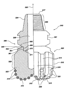
FIG. 2B shows a partial side cross-sectional view of a rotary drill bit 310
(left-hand
side of figure) and a partial side view of rotary drill bit 310 about its
longitudinal axis 333
(right-hand side of figure) prior to welding in accordance with the present
invention.
Rotary drill bit 310 may generally comprise a bit body 323 including a
plurality of
8
CA 02602020 2007-09-24
WO 2006/104885 .PCT/US2006/010775
longitudinally extending blades 314 defining junk slots 316 therebetween. Each
blade 314
may define a leading or cutting face 318 that extends radially along the bit
face around the
distal end 315 of the rotary drill bit 310, and may include a plurality of
cutting element
pockets 319 formed within bit body 323 and oriented for affixing cutting
elements 320
therein to cut a subterranean formation upon rotation of the rotary drill bit
310. Cutting.
elements 320 are shown for illustration only, as they maybe affixed to the
cutting element
pockets 319 after the shank 334 is welded to the bit body 323. Shank 334,
according to the
present invention, may comprise a material having a carbon equivalent of less
than about
0.35%, such as an AISI 4130 or AISI 4130MOD steel. Each blade 314 may include
a
longitudinally extending gage portion 322 that corresponds to the gage 312 of
each blade
314, sized according to approximately the largest-diameter-portion of the
rotary drill bit
310 and thus may be typically only slightly smaller than the diameter of the
hole to be
drilled by rotary drill bit 310. The upper longitudinal end 317 of the rotary
drill bit 310
includes a threaded portion or pin 325 to threadedly attach the rotary drill
bit 310 to a drill
collar or downhole motor, as is known in the art. In addition, the plenum 329
or bore
longitudinally extends within rotary drill bit 310 for communicating drilling
fluid
therewithin through nozzles 336 disposed on the face of the rotary drill bit
310 through
passages (not shown extending from plenum 329 to nozzles 336. Threaded portion
325
may be machined directly into the upper longitudinal end 317 of the shank 334
as may bit
breaker surface 321 for loosening and tightening the tapered threaded portion
325 of the
rotary drill bit 310 when installed into the drill string, the shank 334
engaging the bit body
323 of the rotary drill bit 310 at its distal end as depicted in the cross-
sectional view
thereof.
Also as shown in FIG. 2B, the tapered surface 350 of the shank 334 may
matingly
engage the tapered surface 351 of the bit body 323 in order to position the
shank 334 in
relation to the bit body 323. Of course, vertical surface 360 of shank 334 may
engage
vertical surface 361 (vertical surfaces 360 and 361 not necessarily being
threaded as
depicted in FIG. 2B) and horizontal surface 360 of shank 334 may or may not
engage
horizontal surface 371 according to actual clearances therebetween, the
desirability of a gap
being heretofore described with respect to FIG. 2A. Weld recess 339 may be
formed by
tapered surface 350 of shank 334 and tapered surface 352 of the bit body 323.
9
CA 02602020 2007-09-24
WO 2006/104885 PCT/US2006/010775
A multi-pass weld of the present invention, as described hereinbelow, may be
formed and disposed generally within weld recess 339. As noted above, shank
334 may
comprise a material having a carbon equivalent of less than about 0.35%, such
as, for
example, an AISI 4130, an AISI 4130MOD steel, or an equivalent material.
Therefore,
preheating shank 334 prior to initiating the welding process may not be
necessary. As a
further advantage, aligning the shank 334 with respect to the bit body 323 and
then tack-
welding the assembly together may be accomplished. FIG. 2C shows a schematic
top
cross-sectional view of multi-pass weld 401 of the present invention in
relation to the inner
apex or tip 340 of the weld recess 339 as shown in FIG. 2B. More particularly,
FIG. 2C
shows a top view of the inner boundary of weld recess 339 as defined by tip
340 thereof as
well as welds 410, 420, 430, and 440. Welds 410, 420, 430, and 440 are
depicted as
concentric rings or circles of increasing diameter and are shown as being
separate from one
another. However, FIG. 2C is merely schematic, and welds 410, 420, 430, and
440 are
depicted as shown merely for clarity. Welds 410, 420, 430, and 440 may be
disposed
anywhere generally within weld recess 339, depending on the size of the
previous welding
passes and the size of the welding recess 339. Of course, the longitudinal
position of any
weld of the present invention may be varied in order to fill the weld recess
relatively
evenly.
As shown in FIG. 2C, a first weld 410 or "root" weld may be deposited within
the
weld recess 339, or more specifically, positioned along the circumference of
tip 340 of the
weld recess 339 formed by the interface between the facing surfaces 350 and
352 of the
shank 334 and the bit body 323. First weld 410 may extend around the
circumference of
tip 340 of weld recess 339. First weld 410, as shown in FIG. 2C, may originate
at
circumferential position 409 and may also terminate thereat. Alternatively,
first weld 410
may originate at a first circumferential position and may terminate at a
second
circumferential position. Second weld 420, as shown in FIG. 2C, may originate
at
circumferential position 419 and may terminate thereat. Alternatively, second
weld 420
may originate at a first circumferential position separated from the
circumferential
origination position of the first weld 410 by at least about 90 and may
terminate at a
second circumferential position.
Therefore, circumferential position 409 may be separated from circumferential
position 419 by at least about 90 , measured in relation to the longitudinal
axis 333 of drill
CA 02602020 2007-09-24
WO 2006/104885 PCT/US2006/010775
bit 310, either in the clockwise or counter-clockwise direction. Separation
angle 0, shown
by FIG. 2C, illustrates such a measure of separation between circumferential
position 409
and circumferential position 419. Further, second weld 420 may originate at a
first
circumferential position separated from the originating circumferential
position of the
immediately preceding weld by at least about 90 , and may terminate at a
second
circumferential position. In addition, second weld 420 may be formed about
longitudinal
axis 333 in a circumferential direction (clockwise or counter-clockwise)
opposite to or
consistent with the direction that the initial weld 410 was formed.
Third weld 430, as shown in FIG. 2C, originates at circumferential position
429 and
also terminates thereat. More generally, third weld 430 may originate at a
first
circumferential position separated from the originating circumferential
position of the
immediately preceding weld by at least about 90 , and may terminate at a
second
circumferential position. Fourth weld 440, as shown in FIG. 2C, originates at
circumferential position 439 and also terminates thereat. Similarly, fourth
weld 440 may
originate at a first circumferential position separated from the originating
circumferential
position of the immediately preceding third weld 430 by at least about 90 ,
and may
terminate at a second circumferential position. As may also be seen from FIG.
2C,
circumferential originating positions 409, 419, 429, and 439 may be
substantially
symmetrically distributed about the circumference of tip 340 of weld recess
339.
Of course, the separation between an originating position of a preceding weld
and
the originating position of a subsequent weld may be measured in relation to
the
circumferential distance therebetween. For instance, the circumferential
separation
distance between circumferential position 409 and circumferential position 419
may be at
least about one quarter of the circumference of the circle depicting weld
recess tip 340.
Therefore, a multi-pass weld of the present invention may include an initial
weld
originating at a first circumferential position and terminating at a second
circumferential
position and a second weld originating at a circumferential position at least
about 90 from
the first position of the first weld or at least about one quarter of the
circumference of the
tip 340 of weld recess 339. Subsequent welds may originate at respective
circumferential
positions that are separated by at least about 90 from the circumferential
originating
position of their immediately preceding weld or a distance of at least about
one quarter of
the circumference of the tip 340 of weld recess 339, therearound,
respectively.
11
CA 02602020 2007-09-24
WO 2006/104885 PCT/US2006/010775
Circumferential positions may only be separated by up to 180 , since such
positioning
would be on opposite sides of a line from one edge of the circumference
through the center
thereof to the other side of the circumference. Thus, subsequent welds may
originate at
respective circumferential positions that are separated from the originating
position of the
immediately preceding weld by about 90 to 180 from the originating position
of the
immediately preceding weld in accordance with the present invention. Such a
weld
configuration may reduce, equalize, or minimize distortion and misalignment
between the
assembled shank 334 and bit body 323.
As a further example of the multi-pass weld of the present invention, and
without
limitation, FIG. 2D shows a top cross-sectional view of multi-pass weld 402 in
relation to
the tip 340 of the weld recess 339 as shown in FIG. 2B. Welds 452, 454, 456,
458, 460,
and 462 may be formed and extend around the circumference of the tip 340 of
weld recess
339. First weld 452 may originate at circumferential position 453 and may also
terminate
thereat. Second weld 454 may originate at circumferential position 455 and may
also
terminate thereat. Third weld 456, may originate at circumferential position
457 and may
also terminate thereat. Fourth weld 458, may originate at circumferential
position 459 and
may also terminate thereat. Fifth weld 460, may originate at circumferential
position 461
and may also terminate thereat. Sixth weld 462, may originate at
circumferential position
463 and may also terminate thereat.
Alternatively, and more generally, each weld 452,454,456,458,460, and 462 may
originate at a first circumferential position that is offset from or separated
from the
circumferential origination position of its preceding weld. Thus, subsequent
welds 454,
456, 458, 460, and 462, meaning welds that occur after a preceding weld, may
originate at
a circumferential position separated from the originating circumferential
position of the
immediately preceding weld by at least about 90 or at least about one quarter
of the
circumference of weld tip 340. For instance, separation angle 0, shown by FIG.
2D,
illustrates a measure of separation between circumferential position 459 and
circumferential position 463 of about 120 . Put another way, the separation
distance
between circumferential position 459 and circumferential position 463 as shown
in
FIG. 2D is about one third of the circumference of the circle depicting weld
recess tip 340.
Further, welds 452, 454, 456, 458, 460, and 462 may be formed about
longitudinal axis
333 along any circumferential direction (clockwise or counter-clockwise).
12
CA 02602020 2007-09-24
WO 2006/104885 PCT/US2006/010775
Thus, the multi-pass weld of the present invention is not limited to any
particular
number of discrete welds, but rather comprises more than one weld wherein the
origination
position of a preceding and subsequent weld is separated by at least about 90
or at least
about one quarter of the circumference of the weld recess tip. Further, the
welds may or
may not extend circumferentially or at all. For instance, the welds may be
formed by
applying a heat source and welding medium at a particular position, forming a
weld and
then positioning the heat source and welding medium at a second position and
forming
another weld. Thus, welds may be formed within a weld recess at discrete
locations. In
addition, the separation between the circumferential position of origination
between a
preceding and immediately subsequent weld may vary. For instance, the
separation angle 0
may be about 90 , then about 135 , then about 180 , for the second weld, the
third weld,
and the fourth weld, respectively, without limitation. Further, the
origination positions of
the welds may form a substantially symmetrical pattern, or may form an
unsymmetrical
pattern.
FIG. 3A shows a partial cross-sectional view of an interface 200 between a
shank
216 and a bit body 223 with respect to bore 212 centered about central axis
203 of a rotary
drag bit (remainder not shown). Shank 216 may comprise a material having a
carbon
equivalent of less than about 0.35% and may include tapered surface 260,
tapered surface
250, and horizontal surface 253. Tapered surface 250 of shank 216 may be
configured to
matingly engage tapered surface 251 of bit body 223 to position shank 216 with
respect to
bit body 223. Further, gap 211 may separate horizontal surface 253 of shank
216 and
horizontal surface 252 of bit body 223, thus inhibiting engagement
therebetween that may
affect the proper mating engagement between tapered surface 250 of shank 216
and tapered
surface 251 of bit body 223. Weld recess 239 maybe formed by the intersection
of tapered
surface 260 of shank 216 with tapered surface 241 of bit body 223. As maybe
further seen
in FIG. 3A, tapered surface 251 and horizontal surface 252 of bit body 223 may
form a
cavity which the lower longitudinal end of shank 216 fits within. Such a
configuration
may be advantageous for distributing stresses transmitted through the shank
216 during
operation of the rotary drag bit.
Alternatively, gap 211 may be reduced or eliminated by way of a longitudinal
force
applied to compress the bit body 223 and the shank 216 against one another.
Stated
another way, it may be desirable to configure tapered surface 250 of shank 216
and tapered
13
CA 02602020 2007-09-24
WO 2006/104885 PCT/US2006/010775
surface 251 of bit body 223 so that a sufficient compressive force causes
sliding
therebetween, reducing gap 211 or causing horizontal surface .253 of shank 216
to engage
horizontal surface 252 of bit body 223. Such a compressive force may be
applied prior to
or during welding of the shank 216 to the bit body 223, or both, and may be
desirable as
generating a tensile residual stress within the multi-pass weld (FIGS. 2C and
2D) that may
be counter-acted by the compressive forces experienced during drilling. Such a
configuration may reduce the stresses in the weld during drilling. As a
further alternative,
gap 211 may be eliminated by sizing the shank and bit body accordingly.
FIG 3B shows a partial cross-sectional view of another embodiment of
interface 201 between shank 216 and bit body 223 with respect to bore 212
centered about
central axis 203 of a rotary drag bit (remainder not shown). Shank 216 may
comprise a
material having a carbon equivalent of less than about 0.35%, such as, for
example, an
AISI 4130 or AISI 4130MOD steel and may include tapered surface 260, tapered
surface
250, and horizontal surface 253. Tapered surfaces 250 and 260 of shank 216 may
be
configured to matingly engage tapered surfaces 251 and 261 of bit body 223,
respectively,
to position shank 216 with respect to bit body 223. Such a dual-taper
configuration may be
advantageous for positioning the shank 216 with respect to the bit body 223.
Further, gap 211 may separate horizontal surface 253 of shank 216 and
horizontal
surface 252 of bit body 223, thus inhibiting engagement therebetween that may
affect the
proper mating engagement between tapered surfaces 250 and 260 of shank 216 and
tapered
surfaces 251 and 261 of bit body 223, respectively. Weld recess 239 may be
formed by the
engagement of tapered surface 260 of shank 216 with tapered surface 241 of bit
body 223.
As may be further seen in FIG. 3B, tapered surface 251 and horizontal surface
252 of bit
body 223 may form a cavity which the lower longitudinal end of shank 216 fits
within.
Such a configuration may be advantageous for distributing stresses transmitted
through the
shank 216 during operation of the rotary drag bit (not shown).
FIG. 3 C shows a partial cross-sectional view of another embodiment of the
present
invention depicting interface 202 between shank 216 and bit body 223 with
respect to bore
212 centered about central axis 212 of a rotary drag bit (not shown). As shown
in FIG. 3C,
tapered surface 270 of shank 216 may be sloped longitudinally downward along a
radially
inward path, and may matingly engage tapered surface 271 of bit body 223,
which may
slope longitudinally upward along a radially outward path. Thus, mating
engagement
14
CA 02602020 2007-09-24
WO 2006/104885 PCT/US2006/010775
between tapered surface 270 of shank 216 and tapered surface 271 of bit body
223 may
position shank 216 with respect to bit body 223. Weld gap 239 may be
substantially
formed by the intersection of tapered surface 241 of bit body 223 and tapered
surface 270
of shank 216. Of course, chamfers and radii at boundaries between adjacent
surfaces may.
be used in accordance with engineering design to facilitate proper engagement
between
tapered surface 270 of shank 216 and tapered surface 271 of bit body 223. As
may also be
seen in reference to FIG. 3 C, tapered surface 271 of bit body 223 may form a
cavity which
the lower longitudinal portion of shank 216 fits within. Such a configuration
may be
advantageous for distributing stresses during operation of the rotary drag bit
(not shown).
In addition, shank 216 may comprise a material having a carbon equivalent of
less than
about 0.35%, in order to eliminate the need for preheating. prior to welding
of the shank
216 to the bit body 223.
FIG. 3D shows a partial cross-sectional view of yet another embodiment of the
present invention depicting interface 204 between shank 216 and bit body 223
with respect
to bore 203 centered about central axis 212 of a rotary drag bit (remainder
not shown). As
shown in FIG. 3D, tapered surface 280 of shank 216 may slope longitudinally
upward
along a radially inward path, and may matingly engage tapered surface 281 of
bit body 223,
which may slope longitudinally downward along a radially outward path. Thus,
mating
engagement between tapered surface 280 of shank 216 and tapered surface 281 of
bit body
223 may position shank 216 with respect to bit body 223.
Weld gap 239 may be substantially formed by the intersection of tapered
surface 282 of bit body 223 and tapered surface 280 of shank 216. Shank 216
may
comprise a material having a carbon equivalent of less than about 0.35%, such
as, for
example, an AISI 4130 steel, an AISI 4'130MOD steel, or an equivalent material
to
eliminate the need for preheating the shank prior to welding the shank 216 and
bit
body 223 to one another. Such a configuration may allow the shank 216 and bit
body 223
to be tack welded in order to maintain the relative positioning thereof prior
to forming the
multi-pass weld as described atove and eliminate conventional preheating
thereof during
welding.
FIG. 3E shows a further embodiment of the present invention depicting a cross-
sectional view of interface 205 between shank 216 and bit body 223. As
mentioned above,
shank 216 may comprise a material having a carbon equivalent of less than
about 0.35%.
CA 02602020 2007-09-24
WO 2006/104885 PCT/US2006/010775
Shank 216 and bit body 223 are shown in relation to bore 203, which is
centered about
central axis 212 of a rotary drag bit (remainder not shown). Tapered surface
292 of shank
216 may matingly engage tapered surface 293 of bit body 223 to position the
shank 216 in
relation to the bit body 223. Also, horizontal surface 300 of shank 216 may
matingly
engage horizontal surface 295 of bit body 223, thereby vertically positioning
the shank 216
in relation to the bit body 223. Gap 299 may exist between tapered surface 290
of shank
216 and tapered surface 297 of bit body 223. Gap 299 may provide clearance for
fitting the
shank 216 and the bit body 223 together. Weld recess 239 may be substantially
formed by
tapered surface 290 of shank 216 and tapered surface 291 of bit body 223.
FIGS. 3F and 3G show a cross-sectional view of interface 206 according to the
present invention between shank 216 and bit body 223. More specifically, a
deformable
element 302 may be positioned between shank 216 and bit body 223. As shown in
FIGS.
3F and 3G, deformable element 302 may be positioned between horizontal surface
304 of
shank 216 and horizontal surface 305 of bit body 223. Gap 311 may exist
initially between
tapered surface 306 of shank 216 and tapered surface 307 of bit body 223.
Further, tapered
surface 303 of bit body 223 may engage tapered surface 308 of shank 216 or,
alternatively,
there may be slight clearance therebetween. However, as shown in FIG. 3G,
shank 216
may be displaced so as to deform deformable element 302 and position tapered
surface 306
of shank 216 to matingly engage tapered surface 307 of bit body. 223, thus
substantially
eliminating gap 311. Such a configuration may be preferable to position the
shank 216 in
relation to the bit body 223 by way of a compressive force. Such a compressive
force may
be applied prior to and/or during welding of the shank 216 to the bit body
223, and may
effect a tensile residual stress within the multi-pass weld (FIGS. 2C and 2D)
that may be
desirable as reducing the stresses in the weld during drilling. Also, as shown
in FIGS. 3F
and 3G, weld recess 339 may be substantially formed by tapered surface 306 of
shank 216
and tapered surface 301 of bit body 223. Exemplary deformable elements 302
include high
temperature elastomeric rings, annular leaf springs and Belleville springs, as
well as
nonresilient deformable materials that may be crushed as gap 311 is
eliminated.
Deformation, resilient or nonresilient, of deformable element 302 may provide
controlled
downward movement of shank 216 as it is caused to engage bit body 223.
FIG. 4 shows an exemplary rotary drag bit 500 according to the present
invention
wherein an interface and multi-pass weld as described above have been
completed to affix
16
CA 02602020 2007-09-24
WO 2006/104885 PCT/US2006/010775
bit body 323, either steel body or matrix-type, to the shank 334. Shank 334
may include bit
breaker surfaces or flats 321 for loosening and tightening the tapered
threaded portion 325
of the rotary drag bit 500 when installed into the drill string. Rotary drag
bit 500 may
include radially and longitudinally extending blades 314, wherein each.blade
'314 may
define a leading or cutting face 318 and may include a plurality of cutting
elements 320
affixed thereto and oriented therein to cut a subterranean formation upon
rotation of the
rotary drill bit 500. Nozzles 336 may be sized and positioned to communicate
drilling fluid
from the interior of the rotary drag bit 500 to the cutting elements 320 and
blades 314 to
clean cuttings therefrom. Upon completion of multi-pass weld (not shown), the
exterior,
radially outward surface thereof may be machined flush with an outer surface
of bit body
323. Further, it should be understood that the present invention is not
limited to rotary drill
bits fabricated by way of any particular method; rather, the present invention
may be
practiced with rotary drill bits fabricated by any method.
Generally, the tapered surface arrangements and configurations of the present
invention may provide an efficient mechanism to position the shank in relation
to the bit
body in preparation for welding therebetween. In addition, a longitudinal,
generally axial
force may be applied to the shank or bit body as described hereinabove to
facilitate
positioning or centering of the shank in relation to the bit body, with or
without the
disposition of a deformable element therebetween. Also, a longitudinal force
may be
applied to achieve a desired stress state in the assembly in relation to
welding the shank to
the bit body. The longitudinal force may be applied externally, by way of a
piston or by
other force generation means. On the other hand, with respect only to
positioning, the
tapered surfaces of the shank and bit body may be configured and sized so that
the weight
of the shank as it is disposed longitudinally above the bit body facilitates
positioning or
centering thereof in relation to the bit body as it is lowered thereonto. In
such a
configuration, the shank may be "self-centering."
In addition, although the foregoing descriptions depict "tapered surfaces" in
the
form of cross-sectional representations that may imply continuous annular
surfaces such as
frustoconical surfaces, the present invention contemplates that the tapered
surfaces may
comprise more generally tapered features that may or may not be continuous and
may or
may not be linear in cross-section. Likewise, although the foregoing
illustrations and
descriptions may imply an annular weld recess, many alternatives are
contemplated by the
17
CA 02602020 2007-09-24
WO 2006/104885 PCT/US2006/010775
present invention.. For instance, the multi-pass weld of the present invention
may be
formed in relation to, generally, a region configured for- forming a welded
connection
.between the shank and bit body, without limitation.
More specifically, the present invention contemplates that complementary
longitudinal recesses may be formed in the mating ends of both the shank and
bit body for
welding to one another. In other words, the longitudinal mating ends of both
the shank and
bit body may comprise splines that may be aligned to form longitudinal weld
recesses. In
such a configuration, a respective weld may be formed within each aligned
longitudinal
weld recess. However, in such a configuration, the multi-pass weld of the
present
invention may be formed within the longitudinal weld recesses. More
specifically, in such
a configuration, a first weld may originate from a first circumferential
position and a
second weld may originate from a circumferential position separated from the
first
circumferential position. Each subsequent weld may originate from a respective
circumferential position that is at least about 90 from the origination
position of its
immediately preceding weld.
FIG. 5A shows a perspective view of a rotary drill bit 610 prior to welding in
accordance with the present invention. Rotary drill bit 610 may generally
comprise a bit
body 623 including a plurality of longitudinally extending blades 614 defining
junk slots
616 therebetween and having a leading or cutting face 618 that extends
radially along the
bit face of the rotary drill bit 610. Bit body 623 may include a plurality of
cutting elements
620 affixed thereto to cut a subterranean formation upon rotation of the
rotary drill bit 610.
Cutting elements 620 are shown for illustration only, as they may be affixed
to the bit
body 623 after the shank 634 is welded to the bit body 623, in accordance with
conventional practices. Shank 634, according to the present invention, may
comprise a
material having a carbon equivalent of less than about 0.35%. For example, an
AISI 4130
steel, an AISI 4130MOD steel, or any material having a carbon equivalent of
less than
about 0.35% maybe used, without limitation. Each blade 614 may define a
longitudinally
extending gage portion 622 that corresponds to the gage 612 of each blade 614,
sized
according to approximately the largest-diameter-portion of the rotary drill
bit 610. The
upper longitudinal end 617 of the rotary drill bit 610 includes a threaded
portion or pin 625
to threadedly attach the rotary drill bit 610 to a drill string, as is known
in the art. In
18
CA 02602020 2007-09-24
WO 2006/104885 PCT/US2006/010775
addition, drilling fluid may be communicated through nozzles 636 disposed on
the face of
the rotary drag bit 610.
Shank 634 includes longitudinal recesses 650 which correspond to longitudinal
recesses 660 of bit body 623. Further, shank 634 may include tapered feature
670, which
may be configured according to any of the embodiments described in FIGS. 2A,
2B, and.
3A-3G, and which may be termed a protrusion for the sake of convenience only.
Of
course, bit body 623 may include a complementary tapered feature (not shown),
which may
be termed a recess for the sake of convenience only. Upon assembly of shank
634 and bit
body 623, the longitudinal recesses 650 of the shank 634 and the longitudinal
recesses 660
of the bit body 623 may be aligned circumferentially. FIG. 5B shows a partial
top cross-
sectional view of the longitudinal recesses 650 of the shank 634 and the
longitudinal
recesses 660 of the bit body 623 wherein the longitudinal recesses 650 and 660
are
vertically superimposed and circumferentially aligned. Such alignment may form
weld
recesses 655, as shown in FIG. 5B.
Further, according to the present invention, a multi-pass weld may be formed
within weld recesses 655. A first weld 680 is shown in FIG. 5B at a
circumferential
position of origination 682, and may extend longitudinally within the aligned
longitudinal
recesses 650 and 660. A second weld 681 may be formed at a circumferential
position.of
origination 683 that is separated from the circumferential position of
origination 682 of
first weld 680 by at least 90 , as depicted by separation angle 0 in relation
to longitudinal
axis 661. Subsequent welds (not shown) may be positioned so that each
subsequent
circumferential position of origination is separated from the circumferential
position of
origination of its immediately preceding weld.
There are many alternative implementations that are contemplated and
encompassed by the present invention. For instance, a weld region may be
formed by
alignment of spiraled splines or recesses in one or both of the shank and bit
body. Further,
although the multi-pass weld of the present invention may be described in
terms of
preceding and subsequent welds, as hereinabove, it is contemplated that one or
more welds
of the present invention maybe formed substantially simultaneously by way of
application
of multiple heat sources and disposition of welding materials at more than one
location
within a weld region. In such a configuration, a simultaneously formed weld
maybe taken
as either subsequent or preceding in relation to any other weld simultaneously
formed
19
CA 02602020 2007-09-24
WO 2006/104885 PCT/US2006/010775
therewith, without limitation. For example, without limitation, the present
invention
contemplates that two welds may be formed substantially simultaneously,
separated by a
separation angle of at least about 90 . Further, for example, without
limitation, the present
invention contemplates that three welds may be formed substantially
simultaneously,
wherein at least two of the three welds are separated by at least about 90 .
Such a
configuration may increase the cost of the welding equipment, but may also
increase the
speed or performance of the welding-process and further reduce any tendency
toward
misalignment of the shank and bit body that may be induced by welding.
While the present invention. has been described herein with respect to certain
preferred embodiments, those of ordinary skill in the art will recognize and
appreciate that
it is not so limited. Rather, many additions, deletions and modifications to
the preferred
embodiments may be made without departing from the scope of the invention as
hereinafter claimed. In addition, features from one embodiment may be combined
with
features of another embodiment while still being encompassed within the scope
of the
invention as contemplated by the inventors. Further, the invention has utility
in drill bits
and core bits having different and various bit profiles as well as cutter
types.