Note: Descriptions are shown in the official language in which they were submitted.
CA 02607316 2007-11-01
WO 2006/116853 PCT/CA2006/000678
I SPINAL STABILISATION IMPLANT
2
3 FIELD OF THE INVENTION
4 [0001] The present invention relates generally to the field of joint
implants and, more
particularly, to an implant for use in the stabilisation of spinal elements
such as facet joints or
6 other spinal ligaments. More specifically, the invention relates to implants
for stabilizing
7 cervical vertebrae of the spine.
8 DESCRIPTION OF THE PRIOR ART
9 [0002] The spine is a complicated structure comprised of various anatomical
components, which, while being extremely flexible, provides structure and
stability for the
11 body. The spine is made up of vertebrae, each having a ventral body of a
generally
12 cylindrical shape. Opposed surfaces of adjacent vertebral bodies are
connected together and
13 separated by intervertebral discs (or "discs"), comprised of a
fibrocartilaginous material. The
14 vertebral bodies are also connected to each other by a complex arrangement
of ligaments
acting together to limit excessive movement and to provide stability.
Vertebrae also include
16 thick lateral portions referred to as lateral masses. Each lateral mass
includes facets on the
17 superior and inferior ends thereof. The superior facets of one vertebra are
adapted to engage
18 the inferior facets of the next superiorly adjacent vertebra. The
engagement of the facets is
19 referred to as a facet joint.
[0003] A stable spine is important for preventing incapacitating pain,
progressive
21 deformity and/or neurological compromise. Current methods for surgical
management of
22 ligamentous insufficiency in the spine involve removal of facet joint
capsules and arthrodesis
23 of the joint. In such cases, and in particular in treating instability of
the lower cervical spine,
24 it is common to utilize screws extending through the lateral mass of
adjacent vertebrae. One
of the complications involved in such procedure comprises injury to the spinal
nerves during
26 insertion of the lateral mass screws. In addition, with these prior art
methods, reconstruction
27 of the facet joint capsule is impossible. Removal of the facet joint
eliminates motion at the
28 segment of the spine where the facet joint capsule has been removed, and
can lead to
29 accelerated degeneration of adjacent structures.
-1-
CA 02607316 2007-11-01
WO 2006/116853 PCT/CA2006/000678
1 SUMMARY OF THE INVENTION
2 [0004] The present invention, in one aspect, provides an implant that
obviates or
3 mitigates at least some deficiencies in prior art methods.
4 [0005] In general terms, the invention provides, in one aspect, a spinal
stabilization
implant having three main components: two staples (or anchor plates)
positioned superiorly
6 and inferiorly on the spine, each being secured, respectively, to two
adjacent vertebrae; and a
7 resilient synthetic ligament extending there-between. The staples are
secured to the spinal
8 structure by screws, pins, bolts and other similar means. Implants as
described herein are
9 preferably provided in pairs on laterally opposite sides of the spine. The
implants serve to
provide resistance to inter-vertebral movement such as during flexion.
11 [0006] In one aspect, the implants described herein are suited for
reconstruction of facet
12 joint ligaments and, in such case, the respective staples are secured to
lateral masses of
13 vertebrae.
14 [0007] In another aspect, the implants described herein are suited for
securing to spinous
processes for interspinous and/or supraspinous ligamentous reconstruction.
16 [0008] In another aspect, the implants are adapted to comprise an
artificial spinous
17 process and lamina for use as a prosthesis.
18 [0009] Thus, in one aspect, the invention provides a spinal stabilization
implant for
19 attaching to two adjacent vertebrae, the vertebrae having one or more bony
structures, the
implant comprising:
21 - a pair of first spaced apart anchor plates for securing to a first of the
vertebrae;
22 - a pair of second spaced apart anchor plates for securing to a second of
the vertebrae;
23 - each of the pairs of anchor plates generally being co-planar;
24 - the first and second anchor plates including one or more fastener
apertures for
receiving fasteners to engage the bony structures of the vertebrae;
26 - each of the pairs of anchor plates being connected to a generally planar
fin, the fin
27 being generally perpendicular to the plane containing the respective pairs
of anchor plates
28 and wherein the fin includes a first, anchor plate connecting end and an
oppositely directed
29 second, free end;
-2-
CA 02607316 2007-11-01
WO 2006/116853 PCT/CA2006/000678
I - the fins being connected to a resilient member extending there-between.
2 [0010] In another aspect, the invention provides an implant as defined above
and wherein
3 the first and second anchor plates are provided in pairs so as to straddle
opposite sides of the
4 vertebrae, wherein the implant comprises a pair of first anchor plates are
securing to the first
vertebra and a pair of second anchor plates for securing to the second
vertebra.
6 [0011] In yet another aspect, the invention provides a spinal stabilization
prosthetic
7 implant for attaching to two adjacent vertebrae, the vertebrae having one or
more bony
8 structures, the implant comprising:
9 - a first anchor plate for securing to a first of the vertebrae;
- a second anchor plate for securing to a second of the vertebrae;
11 - the first and second anchor plates including one or more fastener
apertures for
12 receiving fasteners to engage the bony structures of the vertebrae;
13 - a resilient member extending between the first and second anchor plates
allowing
14 elastic relative movement between the anchor plates.
[0012] In another aspect, the above prosthetic implant comprises spacer arms
extending
16 between each of the pair of anchor plates and the respective fin thereby
connecting the fin to
17 the respective anchor plates.
18 [0013] In yet another aspect, the invention provides a kit for a spinal
stabilization implant
19 for attaching to two adjacent vertebrae, the kit comprising:
- first and second anchor plate for securing to the vertebrae;
21 - one or more fastening means to fasten the anchor plates to the vertebrae;
22 - at least one resilient member for connecting the first and second anchor
plates.
23 BRIEF DESCRIPTION OF THE DRAWINGS
24 [0014] Various objects, features and attendant advantages of the present
invention will
become more fully appreciated and better understood when considered in
conjunction with
26 the accompanying drawings, in which like reference characters designate the
same or similar
27 parts throughout the several views.
-3-
CA 02607316 2007-11-01
WO 2006/116853 PCT/CA2006/000678
I [0015] Figure 1(a) is a top (superior) view of a lateral mass staple
according to an
2 embodiment of the invention.
3 [0016] Figure 1(b) is a side elevation of the staple of Figure 1(a).
4 [0017] Figure 2(a) shows a bottom (inferior) view of the staple of Figure
1(a).
[0018] Figure 2(b) shows a front elevation of the staple of Figure 1(a).
6 [0019] Figure 3 is a perspective view of lateral mass staples according to
an embodiment
7 of the invention when implanted.
8 [0020] Figure 4 is a perspective view of an embodiment of the invention when
implanted
9 and when the spine is in extension.
[0021] Figure 5 is a perspective view of an embodiment of the invention when
implanted
11 and when the spine is in flexion.
12 [0022] Figures 6a-6c show plan views of alternate embodiments of the
lateral mass
13 staples of the invention.
14 [0023] Figure 7 is a plan view of an alternate embodiment of the present
invention.
[0024] Figure 8(a) is an outer side elevation of a right side portion of a
spinous process
16 staple according to an embodiment of the invention.
17 [0025] Figure 8(b) is an outer side elevation of a left side portion of a
spinous process
18 staple according to an embodiment of the invention.
19 [0026] Figure 8(c) is an inner side elevation of the staples of Figures
8(a) or 8(b).
[0027] Figure 8(d) is a side view of a spine wherein the spinous process
staples are
21 attached.
22 [0028] Figure 8(e) is a perspective view of the spinous process staple
according to an
23 embodiment of the invention.
24 [0029] Figure 9a is a posterior elevation of a spine segment illustrating
two adjacent
vertebrae.
-4-
CA 02607316 2007-11-01
WO 2006/116853 PCT/CA2006/000678
1 [0030] Figure 9b is a side elevation of the spine segment of Figure 9a.
2 [0031] Figure l0a is a plan view of an artificial spinous process according
to another
3 aspect of the invention.
4 [0032] Figure l Ob is a perspective side elevation of the device of Figure
10a.
[0033] Figures 11 a to 11 c illustrate the device of Figure I Oa when in use.
6 DETAILED DESCRIPTION OF THE INVENTION
7 [0034] In order that the invention may be more fully understood, it will now
be described,
8 by way of example, with reference to the accompanying drawings which
illustrate
9 embodiments of the present invention.
[0035] In the description and drawings herein, and unless noted otherwise,
when
11 discussing anatomical plans of view, it will be understood that the terms
"front" and "back"
12 shall be used to refer to the front and back in the coronal or frontal
plane. The terms "left"
13 and "right" shall be used to refer to left and right in the sagittal or
lateral plane. The terms
14 "up" and "down" shall be used to refer to up and down in the axial
transverse. It will be
understood that a reference to "medial" shall refer towards the midline of a
body. It will be
16 understood that a reference to "lateral" shall refer to away from the
midline of a body. It will
17 be understood that a reference to "inferior" shall refer to lower, below or
down and
18 "superior" shall refer to upper, above or up. It will be further understood
that a reference to
19 "anterior" shall refer to front and "posterior" shall refer to the rear or
back.
[0036] The present invention provides an implant for use in ligamentous
reconstruction
21 of joints undergoing or experiencing ligamentous insufficiency. A preferred
embodiment of
22 the present invention provides an implant for use in ligamentous
reconstruction of joints
23 within the spine undergoing or experiencing ligamentous insufficiency, such
as facet or other
24 joints therein. The embodiments of the present invention may also be used
to secure
ligamentous material to normal or artificial laminae, pedicles, lateral
masses, or other regions
26 of the vertebrae. The embodiments of the present invention may also be used
to reconstruct
27 joints including spinal joints such as, for example, facet joints or facet
joint capsules. While
28 it will be understood that the invention may be used in a variety of
joints, including spinal
29 joints in general, a preferred embodiment of the invention is the use of
the present invention
-5-
CA 02607316 2007-11-01
WO 2006/116853 PCT/CA2006/000678
I in facet joints or facet joint capsules collectively referred to as "facet
joints" undergoing or
2 experiencing ligamentous insufficiency.
3 [0037] Figures 9A and 9B illustrate two adjacent vertebrae, a superior
vertebra 200a and
4 an inferior vertebra 200b. Each of superior and inferior vertebra includes,
respectively, a
right lateral mass (202a and 202b) and a left lateral mass (204a and 204b).
Figure 9A
6 illustrates the right and left superior facets 206a and 207a, respectively,
on the right and left
7 lateral masses 202a and 204a. The opposing superior and inferior facets of
the adjacent
8 vertebrae form facet joints 280 and 210. As will be understood by persons
skilled in the art,
9 typical spinal structure would also include ligaments and the like (not
shown in Figure 9) to
maintain the vertebrae in the normal position and to allow flexion there-
between. As
11 discussed above, in certain cases, such ligaments are rendered damaged or
weakened (i.e.
12 "insufficient") for a variety of reasons. Such ligamentous insufficiency
results in pain and/or
13 damage to related spinal structures.
14 [0038] One method for reconstructing the ligaments of a facet joint
involves the
attachment of native, artificial, or synthetic ligamentous material so as to
replace or augment
16 ligaments within areas or regions of ligamentous insufficiency. It will be
understood that
17 several types of material are suitable for use as the ligamentous material
of the present
18 invention. The ligamentous material could be native or artificial ligament,
tendon, or fascia,
19 or manufactured material of a flexible (i.e. resilient) and durable nature.
The ligament might
also be a manufactured of a synthetic flexible matrix into which cells, such
as fibroblasts, can
21 impregnate or migrate. The matrix, by means of its structure and by
chemicals possibly
22 contained within it, could facilitate "directed growth", such that the
growth of the migrating
23 cells within the matrix is encouraged. By including growth promoting agents
within the
24 matrix, the migrating cells deposit compounds, such as collagen and/or
other proteins, so as
to produce a new ligament made of human tissue. Generally, as used herein, the
term
26 "synthetic" may comprise both organic and non-organic material. For
example, with respect
27 to organic material, the "synthetic" ligament may comprise a ligamentous
graft such as an
28 autograft, allograft, or xenograft. Alternatively, the synthetic ligament
may comprise other
29 organic tissue having the required physical requirements such as fascia, or
bovine
pericardium. In general, the material is one that mimics the elastic nature of
natural
31 ligaments as found in the body. Ligaments serve to limit range of motion in
a manner
32 analogous to a tension band. In this capacity, ligaments found in the spine
offer physiologic
-6-
CA 02607316 2007-11-01
WO 2006/116853 PCT/CA2006/000678
1 non-rigid spinal stabilization. With respect to inorganic materials for
manufacturing the
2 synthetic ligament, many options are possible. As will be appreciated by
persons skilled in
3 the art, the synthetic ligaments that can be used in the present invention
are manufactured
4 from a fabric or fabric-like tension band having physical properties
approximate that of
naturally occurring ligaments. By way of example only, one possible synthetic
ligament that
6 may be used in the implant described herein comprises the Leeds-Keio
artificial ligament,
7 which was developed by the University of Leeds (UK) and Keio University
(Japan). Such
8 artificial ligament comprises a polyester material having a mesh structure
and has been
9 investigated for use as a spinal ligament prosthesis (Suzuki K., Mochida J.,
Chiba M.,
Kikugawa H., Posterior Stabilization Of Degenerative Lumbar Spondylolisthesis
With A
11 Leeds-Keio Artificial Ligament. A Biomechanical Analysis In A Porcine
Vertebral Model12 Spine, 1999; 24(1):26-31). Various other materials serving
the same purpose will be known
13 to persons skilled in the art.
14 [0039] The reconstruction of these regions of insufficiency allows for the
maintenance of
motion while reducing the loading of adjacent segments. By creating a lateral
mass staple
16 assembly as described herein, the facet joint can be reconstructed to allow
motion but
17 constraining flexion (i.e. forward or bending motion) so as to prevent
overdistraction. In the
18 present description the terms "staple" or "anchor plate" are used to
describe an anchor that is
19 secured to a bony structure. As discussed further below, such staple may be
screwed, bolted,
pinned or otherwise secured to bone. In one embodiment, the staples are
screwed through an
21 aperture provided therein. In general, the staples of the invention may be
of any acceptable
22 shape for the purpose described here. In one aspect, the staples are
generally flat anchor
23 plates. The staples may include one or more physical and/or chemical
features to enhance
24 bone, muscle, ligament and/or scar tissue in-growth so as to further secure
the staple to the
bone structure once implanted. The staples will generally be shaped, at least
on their bone-
26 contacting surface, to mate with the respective bone structure to which
they are to be
27 attached.
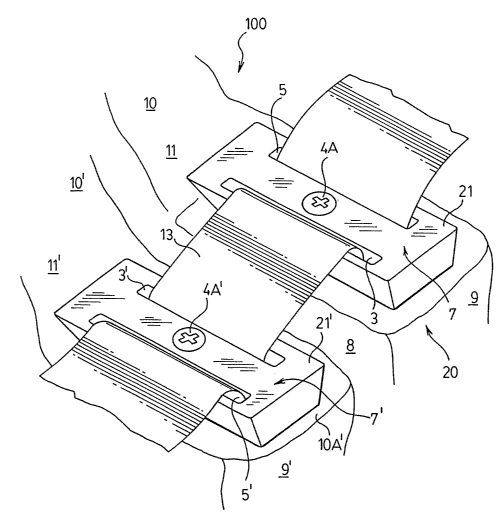
28 [0040] In Figures 3 to 5, there is shown a perspective view of a vertebral
segment 100
29 having facets 10 and 10' of vertebrae 10A and l0A' and a facet joint 8,
which make up the
vertebral segment. As explained above, and as will be understood by persons
skilled in the
31 relevant art, facets are posterior structures of a vertebra which can
articulate with facets of an
32 adjacent vertebra to form facet joints that allows motion in the spinal
column. Each vertebra
-7-
CA 02607316 2007-11-01
WO 2006/116853 PCT/CA2006/000678
I has two (right and left) superior and two inferior facets. There is also
shown, respectively,
2 the lateral mass 9 and 9' of vertebrae l0A and l0A'. It will be generally
understood by
3 persons skilled in the relevant art that the term "lateral mass" refers to
the lateral expansion of
4 the spinal ring such as of the cervical section of the spine, consisting of
the facet joints and
intervening bone as well as a tunnel through which the vertebral artery
travels.
6 [0041] Also provided in Figures 3 to 5 is an embodiment of the lateral mass
staple
7 assembly 20 in accordance with the present invention. Lateral mass staple
assembly 20
8 consists of two facet joint staples, namely a superior or cranial end staple
21 and an inferior
9 or caudal end staple 21'. It will be understood that the terms "superior or
cranial" and
"inferior or caudal" refer to the vertical alignment of the staples when
implanted. As shown
11 in the embodiment depicted in the figures contained herein, the staples may
comprise anchor
12 plates, which are attached on superior and inferior vertebrae l0A and 1
0A', respectively, by
13 fasteners such as 4A. Fasteners 4A would generally include an anchoring
means to engage
14 the bone material of the lateral mass. In one embodiment, the fasteners
include a screw
portion, as shown in Figures 3 to 5, to serve as the anchoring means. In the
figures contained
16 herein, an embodiment is shown wherein one staple is anchored to each side
of a vertebrae.
17 However, it will be understood by persons skilled in the art, particularly
based on the
18 following description, that any number of staples may be used depending on
the need. Thus,
19 for example, two or more facet joint staples can be placed per side into
the lateral masses.
[0042] The staples (i.e. anchor plates) of the present invention may be made
of a suitable,
21 surgical grade metal or metal alloy or other such durable material as will
be known to persons
22 skilled in the art.
23 [0043] It will also be understood that, in a preferred embodiment, the
facet joint staples
24 are provided in left and right sided versions, which correspond to the left
and right lateral
aspects of a vertebra. As shown in the embodiment depicted in Figure 1, each
facet joint
26 staple has a lateral side, which may have a curved contour 25 that allows
for easy orientation.
27 Figures 3 to 5 illustrate an alternate embodiment of the than that of
Figure 1 wherein a
28 different staple design is shown. The lateral sided contour 25 (right side
of diagram in
29 Figures 1 and 2) abuts the lateral aspect of lateral mass 9 and 9' and can
be generally shaped
to conform to the general shape of the lateral mass. This is particularly
suitable for
31 application on axis plates which have a curve to conform to the joint. The
opposing side,
-8-
CA 02607316 2007-11-01
WO 2006/116853 PCT/CA2006/000678
I namely medial side 27 (left side of diagram in Figures 1 and 2), has a
generally straight
2 portion that abuts the lamina 11 and 11'.
3 [0044] As shown in Figures 4 and 5, the invention is provided with a
synthetic ligament
4 13, which is secured to facet joint staples 21 and 21'. As indicated above,
the synthetic
ligament 13 may be made from various materials as will be understood by
persons skilled in
6 the art.
7 [0045] Figures 1 and 2 show additional views of one embodiment of the facet
joint staple
8 of the present invention. The facet joint staple of the present invention
may be manufactured
9 in a variety of shapes and sizes to allow for use in different applications.
A person skilled in
the art will understand that the facet joint staple that will come in a
variety of heights and
11 widths to allow for use in different size patients as well as other
vertebral segments.
12 Considerations for the height and width of the facet joint staples can be
(1) size of patient, (2)
13 region of spine, i.e. cervical, thoracic, or lumbar, and (3) application,
e.g. lateral mass or
14 spinous process. In a preferred embodiment, the implant of the present
invention can be
approximately 2 to 3 mm thick. A facet joint staple having this thickness is
preferred for
16 attachment of ligaments to facet joints.
17 [0046] The facet joint staples 21 and 21' include a first surface 7 and 7',
respectively
18 which comprises the outer surface in the applied position. The staples also
include a second,
19 opposing surface comprising inner surface in the applied position, that is,
the surface
contacting the lateral mass or other spinal structure. In addition, the
staples include first,
21 second, third and fourth edges, 28, 25, 26 and 27 respectively. In the
embodiment of the
22 present invention shown in Figures 1 and 2, a first generally longitudinal
aperture 3 is
23 provided for each staple adjacent edge 26 and generally extends across the
longitudinal axis
24 extending from side 25 and side 27. Longitudinal aperture 3 also defines an
opening between
the outer and inner surfaces. Aperture 3 is adapted to receive a portion of
ligament 13, as can
26 be seen in Figures 3 to 5 and as will be described further below. A second
longitudinal
27 aperture 5 is also provided on each staple. Second aperture 5 also defines
an opening
28 extending between the outer and inner surfaces and is provided adjacent to
edge 28. Similar
29 in configuration to first aperture 3, second aperture 5 is adapted for
receiving a portion of
ligament 13.
-9-
CA 02607316 2007-11-01
WO 2006/116853 PCT/CA2006/000678
1 [0047] Each staple is further provided with a fastener-receiving aperture 4,
extending
2 through facet joint staple. In the embodiment of the present invention shown
in Figures 1 and
3 2, fastener-receiving aperture 4 is provided generally in the center of
facet joint staple 21. In
4 alternate embodiments of the present invention, as seen in Figures 6(a), (b)
and (c), the
fastener-receiving aperture 4 may be in different locations about facet joint
staple 21.
6 Fastener-receiving aperture 4 is adapted to receive a fastener that will
affix facet joint staple
7 21 to vertebrae IOA or l0A'. As shown in Figure 2b, the facet joint staple
may have a
8 medial-lateral curve so as to generally conform with the surface of the
vertebrae to which the
9 facet joint staple is to be attached.
[0048] As shown in the figures, staple 21 is provided with apertures 3 and 5
while staple
11 21 is provided with equivalent apertures 3' and 5'. Longitudinal apertures
3, 3', 5 and 5' are
12 provided with generally smooth surfaces to as to allow ligament 13 to pass
there-through. In
13 a preferred embodiment, the ligament 13 is threaded through each of
apertures 3 and 5 and 3'
14 and 5', respectively as shown. In order to arrange lateral mass staple
assembly 20 once facet
joint staples 21 and 21' have been placed on or affixed to vertebra 10 and
10A', ligament 13
16 can be passed through these longitudinal apertures so as to provide the
necessary stability to
17 the joint as described herein.
18 100491 As shown in the embodiment shown of Figures 4 and 5, in implanting
the device
19 of the invention, the synthetic ligament 13 is passed posterior-inferior
through the apertures 3
and 5 and 3' and 5', respectively. As shown, in this manner, the ligament is
oriented so as to
21 lie between the spinal bone tissue and the inner surfaces 7 and 7'
respectively of staples 21
22 and 21'. As can be seen, in such orientation, the fasteners 4A and 4A' used
to anchor the
23 staples will extend through the synthetic ligament 13. Staples 21 and 21'
can then be affixed
24 through ligament 13 by fastener 4A.
[0050] Figures 4 and 5 show the embodiment of the present invention in use for
the
26 attachment of synthetic ligament 13 to a right facet joint. Two staples 21
and 21' are shown,
27 wherein one is placed on each side of the facet joint and wherein each
staple is attached to the
28 respective lateral mass by fasteners 4A and 4A'.
29 [0051] Figure 4 shows the right facet joint in extension while Figure 5
shows the right
facet joint in flexion. As will be understood by persons skilled in the art,
the term
31 "extension" refers to an anterior to posterior motion of the spine (i.e.
bending backward)
- 10-
CA 02607316 2007-11-01
WO 2006/116853 PCT/CA2006/000678
1 whereas the term "flexion" refers to a posterior to anterior motion of the
spine (i.e. bending
2 forward). As seen in Figure 5, when the spine in which the device of the
invention is
3 implanted is in flexion, the synthetic ligament 13 serves to limit the
degree of flexion in a
4 fashion akin to the in vivo facet joint capsule. On extension of the spinal
segment, the lateral
mass staple assembly of the invention does not limit the range of motion, with
such limitation
6 being the result of natural limits to extension, namely the facet joints
abutting one another.
7 As can be seen in Figure 4, during extension, the synthetic ligament 13 can
buckle and this
8 built in laxity allows the subsequent normal movement of the facet joints in
flexion.
9 [0052] As can be seen in Figure 5, the synthetic ligament 13 has been
stretched taut
across the facet joint 8 in flexion thereby constraining the joint. The
lateral mass staple
11 assembly 20 therefore allows for the stabilization of the facet joint in
flexion. As will be
12 understood by persons skilled in the art, the stabilization implant
described herein is
13 particularly suited for implantation in the cervical segment of the spine
so as to limit neck
14 flexion. In particular, the device disclosed herein allows for
reconstruction of the normal
limitation to flexion provided by facet joint capsules in the cervical spine.
16 [0053] Finally, rotation movement (not shown) with lateral mass staple
assembly 20 will
17 be limited to a degree by the configuration of the underlying facet joint
and contralateral facet
18 joint. However, the properties of ligament 13 could limit excessive
rotation, such as
19 extremes of rotation to the point of subluxation limited by the capsule, as
well as facet
dislocation.
21 [0054] In a preferred embodiment, fastener-receiving aperture 4 can be
threaded for
22 receiving a fastener, such as a screw and more particularly such as a
lateral mass screw as
23 commonly known in the art. Examples of fasteners that may be used in
conjunction with the
24 facet joint staple of the present invention include screws, spikes, pins,
rods, ties, or sutures.
The fasteners can be inserted into the pars interarticularis, lateral mass,
pedicles, spinous
26 processes or any of the other elements in the bony spine. The fastener
could also be inserted
27 into artificial equivalents of the above. It will be understood, however,
that the present
28 invention is not limited to use with these fasteners. For example, in an
alternate embodiment
29 the fastener may be a bolt secured with a nut. Preferably, the fastener-
receiving aperture 4 is
angled, as shown in Figure 1 and 2 as well as Figures 6(a), (b) and (c), to
allow for angular
31 insertion of the fastener into adjacent bone, maximizing bone purchase and
minimizing the
-11-
CA 02607316 2007-11-01
WO 2006/116853 PCT/CA2006/000678
1 chance of the fastener damaging other tissues. This angle is dependent upon
the amount and
2 position of underlying bone in various regions of the spine and the
relationship of
3 surrounding eloquent structures to the bone. The angle allows for a standard
lateral mass
4 screw to be used. Depending on the thickness of the plate portion of a
staple (which may
generally be approximately 2mm or above), obtaining a suitable or satisfactory
trajectory at
6 angle through a straight hole could be a problem for the surgeon. The angle
of fastener-
7 receiving aperture 4 helps to overcome this problem, while allowing for
variations in the
8 thickness of the facet joint staple. In a preferred embodiment, the fastener-
receiving aperture
9 4 can be angled between 20 to 40 degrees laterally (towards 25) from the
outer (7, 7') to the
inner surface and 0 to 20 degrees superiorly (i.e. towards edge 28). More
preferably in a
11 cervical lateral mass and facet application, the angle of fastener-
receiving aperture 4 can be
12 25 in both directions (up and down as well as medial and lateral, referred
to as "upwards and
13 outwards") to allow for either lateral mass or pedicle fixation. It will be
understood that the
14 angulation and position of the fastener-receiving aperture can be varied to
accommodate
various types of fastners, including pedicle or par screws.
16 [0055] The diameter of the fastener-receiving aperture may be varied
depending on the
17 diameter of the fastener used. As fastener 4A attaches or affixes facet
joint staple to adjacent
18 bone structures, it can also pass through ligament 13 so as to affix
ligament 13. As such, the
19 insert of the fastener 4A may aid the in-growth of bony-material around the
ligament
[0056] In another embodiment, the outer surface 7, 7' of the staples may be
provided with
21 a fastener lock for holding fastener 4A inserted into the fastener-
receiving aperture 4 in place.
22 In a preferred embodiment, as shown in Figure 1(b), the lock consists of at
least one rotatable
23 flange 15 that can stop the movement of fastener 4A and prevent it from
being removed from
24 the fastener-receiving aperture 4. Rotatable flange 15 is provided on the
first surface 7, 7'
adjacent to the fastener receiving aperture 4. Once fastener 4A has been used
to affix the
26 spinal implant to bone, the head of fastener 4A protrudes slightly above
the first surface.
27 Flange 15 can then be rotated over the head of fastener 4A, locking
fastener 4A in place and
28 preventing it from working free of the bone. As shown in Figure 1 and in
greater detail in
29 Figure 7, locking flanges 15 and 15' can be moved from a first position
which allows the
entering and exiting of fastener 4A from the fastener-receiving aperture 4 to
a second position
31 that can stop the exiting of fastener 4A from the fastener-receiving
aperture 4. Once fastener
32 4A has been inserted into fastener-receiving aperture 4, locking flanges 15
and 15' can be
- 12-
CA 02607316 2007-11-01
WO 2006/116853 PCT/CA2006/000678
1 moved from the first position to the second position to lock fastener 4A in
place. Although
2 this form of fastener-lock is preferred, the present invention is not
limited to this fastener-
3 lock. Various alternative fastener-locks which help to prevent the fastener
from working free
4 of the bone to which the implant is affixed could be substituted for the at
least one flange.
[0057] Figures 6a, 6b, and 6c show various embodiments of the lateral mass
staple of the
6 invention in which the position of the fastener-receiving aperture 4 is
varied. In a preferred
7 embodiment, the positioning of the fastener-receiving aperture is based on
the region of the
8 spine where the implant is to be used. In figure 6a the fastener-receiving
aperture is provided
9 generally in the center of the facet joint staple. This embodiment is of
particular use for the
attachment of ligaments to the lateral mass of cervical vertebra. In this
embodiment, the
11 fastener-receiving aperture is preferably angled 25 upwards and outwards
relative to the
12 centre of the lateral mass. Figure 6b shows an alternate embodiment of the
facet joint staple
13 in which the fastener-receiving aperture is provided adjacent to one end of
the first
14 longitudinal inferior aperture, such as aperture 3, and adjacent edges C
and D. The
arrangement of fastener-receiving aperture 24 shown in Figure 6b is of
particular use for the
16 attachment of ligaments to the lamina of the C2 vertebra with C2 pars or C2
pedicle screws
17 which can be placed through a more medially placed hole. The pedicle screw
placement is
18 also facilitated through a more lateral screw hole as shown. In this
embodiment, fastener-
19 receiving aperture 4 is preferably angled 45 superiorly.
[0058] Figure 6c shows an alternate embodiment of the facet joint staple in
which the
21 fastener-receiving aperture 4 is provided adjacent the curved contoured
edge B, and between
22 the first aperture 3 and the second aperture 5. This embodiment is
particularly useful for the
23 attachment of ligaments to the C7 vertebra or the thoracic pedicle. In this
embodiment, the
24 fastener-receiving aperture is sized to accommodate larger screws, for
example pedicle
screws. The fastener-receiving aperture is angled 10 inferiorly (towards 26
from 7 to 7') and
26 0 to 45 medially (towards 27 from 7 to 7').
27 [0059] As shown in Figure 2, each of the inside surfaces 7a and 7a' of mass
staple 21 or
28 21', respectively, may also include at least one stabilizing member 1. As
shown in Figure 2,
29 in one embodiment six or more stabilizing members are provided. Stabilizing
members 1 can
penetrate adjacent bony structures, thus allowing fixation of facet joint
staples to the adjacent
31 bony structures. Examples of stabilizing members include, but are not
limited to, teeth, pins,
- 13 -
CA 02607316 2007-11-01
WO 2006/116853 PCT/CA2006/000678
I and spikes. The at least one stabilizing member not only helps to attach the
implant to
2 adjacent structures, but also passes through the ligamentous material or
ligament 13 to allow
3 for bony ingrowth through the ligament. Each of the inside (i.e. bone
contacting) surfaces 7
4 and 7' of later mass staples 21 and 21' preferably has a roughened, porous
surface treatment
or coating to allow for bony ingrowth which aids in the long term fixation of
lateral mass
6 staple assembly 20 to the lateral mass. In one embodiment the area of inside
surfaces 7a and
7 7a' between the first and second longitudinal apertures 3 and 5 can be rough
to allow for
8 increased bone growth in that area. In another embodiment, the inside
surfaces 7a, 7a' can be
9 coated with a porous substance, such as titanium particle spray or
plasmapore. In yet a
further embodiment, inside surfaces 7a and 7a' can include a hollow cage or
similar mesh
11 type structure as will be known to persons skilled in the art, in which to
place a bone growth
12 substance, such as bone morphogenic proteins (e.g. rhBMP2 or rhBMP-7) that
stimulates
13 bone growth into the cage, therefore incorporating bone into the facet
joint staple. Various
14 other similar treatments and coatings may also be provided with such
features being apparent
to persons skilled in the art.
16 [0060] As shown in Figures 1 and 2, inside surfaces 7a and 7a' may also
include one or
17 more reservoirs 2. The reservoirs 2 may contain bone-fusion-enhancing
materials, such as
18 proteins that promote bone growth, in order to encourage in-growth of bone.
In an
19 embodiment of the present invention, reservoir 2 is a generally U-shaped
indentation in
surface 7' along the surface furthest away from the facet joint. In other
words, superior facet
21 joint staple 21 would have reservoir 2 adjacent aperture 5 which is near
the superior end, but
22 for the inferior joint staple 21', the reservoir would be located adjacent
aperture 5' which is
23 near the inferior end of the structure. It will be understood that if three
or more facet joint
24 stables are to be used, then the middle staple or staples can have
reservoirs adjacent both
aperture 3 and aperture 5. The configuration in figure 3 is only an example of
two abutting
26 facet staples.
27 100611 An alternate embodiment of the present invention is shown in Figures
8a to 8e
28 wherein a staple is provided for attachment to a spinous process. Spinous
process staple 110,
29 as shown in figure 8(e), is designed to permit attachment of synthetic
ligaments (not shown)
to spinous processes 150 of Figure 8(d) in the same manner as described above.
Staple 110
31 as shown in Figures 8(a) to 8(e) may be used for ligamentous reconstruction
of interspinous
32 and supraspinous ligaments, and also for limiting flexion of the spine.
Staple 110 is adapted
-14-
CA 02607316 2007-11-01
WO 2006/116853 PCT/CA2006/000678
1 to straddle spinous process 150 of vertebrae 120. Generally U-shaped staple
110 includes a
2 first and second arm 111 and 112, respectively. As shown in Figure 8(e),
first and second
3 arm have exterior surfaces 114 and 115 on one arm of the U-shaped staple
110, and an
4 interior surfaces 116 and 116' on the opposite side of the first surface 114
and second
surfaces 115.
6 100621 Each exterior surface, and its corresponding interior surface,
includes at least two
7 apertures (122,123,124,125) extending through the 'body of each arm to allow
passage of
8 ligaments therethrough. In addition, each exterior surface, and its
corresponding interior
9 surface, includes a fastener-receiving aperture (130, 132) to allow passage
of a fastener
therethrough and into the adjacent spinous process.
11 [0063] At least one of the exterior surfaces includes a fastener lock that
functions as
12 described further above. In the embodiment shown in Figures 8(a) to (e) the
fastener lock is
13 included on the first exterior surface 114 consists of a pair of flanges
140.
14 [0064] The first and second interior surfaces of the implant 110 may
include all the
features of the second surface 7' of the staple 10 described above including
stabilizing
16 members, reservoirs for containing bony-fusion enhancing materials, and a
plurality of pores
17 to encourage in-growth of bone.
18 [0065] From the above discussion, various unique features of the invention
can be
19 determined. Firstly, the spinal stabilization implant discussed herein
comprises an efficient
facet joint capsule reconstruction, particularly for the cervical spine. It
will also be
21 understood that the embodiment described above for use on spinous processes
also allows for
22 ligamentous reconstruction of interspinous and supraspinous ligaments as
well as allowing
23 for dynamic limitation of flexion in the spine.
24 [0066] One of the unique features of the present device is that it provides
for rapid and
long term fixation of a synthetic ligament to lateral masses. This is achieved
primarily by the
26 structural features of the staples. For example, the porous surface
structure of the staples
27 promotes bony in-growth into to the staple. Further, the stabilizing
members (for example
28 pins) capture the bony regions of the lateral mass and, in addition, where
they pass through
29 the synthetic ligament, they promote bony in-growth there-through. The bony
fusion
-15-
CA 02607316 2007-11-01
WO 2006/116853 PCT/CA2006/000678
enhancing material reservoirs (2) also promote bone in-growth through the
synthetic
2 ligament.
3 [0067] Another feature of the invention comprises the medial to lateral
contouring of the
4 staple undersurface which facilitates placement onto for example the lateral
mass.
[0068] It will be understood by persons skilled in the art that various
methods may be
6 employed to secure the synthetic ligament to the staples. As described
above, the synthetic
7 ligament is, in one embodiment, held in place by both the securing fastener
(e.g. a screw such
8 as a lateral mass screw) and the stabilizing members (e.g. stabilizing
pins). Alternatively, the
9 synthetic ligament may be clipped, screwed or otherwise secured to the
respective staple in
any other manner while achieving the same purpose.
11 [0069] In the above description and as shown in Figures 1 to 8, an
embodiment of the
12 invention have been illustrated with respect to two staples being provided.
However, as will
13 be understood, in the course of stabilizing a spine in the present manner,
it may be necessary
14 to apply the present device to a number of vertebrae to achieve the desired
stability. In this
manner, the synthetic ligament can be continuous on each side, being secured
to each staple
16 along its length. Alternatively, the synthetic ligament can be provided in
various sections,
17 each section being secured in succession so as to effectively achieve a
unified ligament. It
18 will also be appreciated that the synthetic ligaments used in the present
invention will be
19 selected for length and elastic capability based on the specific needs.
[0070] The fastener receiving aperture of the staple is preferably angled, as
explained
21 above, to allow for, for example, the placement of lateral mass screws. In
addition, this angle
22 can be altered as needed in order to accommodate different screw
trajectories such as screws
23 into the pars of the C2 vertebra as well as pedicles. Various other angles
and orientations will
24 be apparent to persons skilled in the art depending upon the desired bone
structure into which
the staples are to be anchored. For example, the staples of the invention can
be secured to
26 artificial laminae, pedicles, lateral masses or vertebrae or any
combination thereof.
27 [0071] As will be understood by persons skilled in the art, the straight
medial edge of one
28 embodiment of the staples will not interfere with potential decompressive
procedures such as
29 a laminectomy. As described above, the straight edge can straddle the of
the decompression.
-16-
CA 02607316 2007-11-01
WO 2006/116853 PCT/CA2006/000678
i [0072] Another unique feature of the device described herein is the use of a
"belt buckle"
2 method of attaining immediate fixation of the synthetic ligament to the
staple and the
3 associated bone structure (i.e. lateral mass). Such method, along with the
selection of a
4 suitably elastic ligament material allows for a certain amount of elasticity
similar to a normal
facet joint capsule. This unique attachment means also stabilizes the facet in
rotational
6 motions as a result of it low profile (i.e. being located directly on the
lateral mass).
7 [0073] A further embodiment of the invention is shown in Figures 10 to 11.
In these
8 figures the stabilizing implant comprises an artificial spinous process and
lamina for the
9 vertebra with such implant being attached to other bony structures of the
vertebra such as the
lateral masses. In this embodiment, the implant 300 is designed to be
positioned over a
11 region of a spine where the naturally occurring spinous process and, in
some case, lamina are
12 excised to expose the spinal cord and dura. As will be known to persons
skilled in the art,
13 such a procedure may comprise a decompressive laminectomy. The implant 300
can be
14 attached to various sections of the vertebra such as the lateral masses
etc. Alternatively, the
implant 300 can be attached to other staples such as those discussed above
(and referred to as
16 items 21 and 21' in previous figures), or other similar prostheses such as
an artificial facet
17 joint and the like.
18 [0074] As shown in Figures IOa and lOb, the implant 300 includes two
laterally
19 extending and spaced apart staples 302 and 304, which, in one embodiment,
comprise lateral
mass staples. That is, the staples 302 and 304 are designed to be affixed to
the two lateral
21 masses on a vertebra. The staples 302 and 304 comprise anchor plates
adapted to be attached
22 to the desired bony structure. It will be appreciated that the staples 302
and 304 may include
23 the various bony in-growth promoting means as described above. Further the
staples 302 and
24 304 include a fastener receiving aperture to provide an aperture through
which an anchoring
means such as screws (i.e. lateral mass screws), pins and the like may be
passed through to
26 engage the underlying bony structure. As illustrated, the two staples 302
and 304 are
27 generally flat plates each lying generally on the same plane. It will be
understood that this
28 description of orientation is not meant to be limiting in any way. That is,
in many
29 circumstances, the staples 302 and 304 may not be exactly co-planar and
may, in fact, be
slightly angled with respect to each other in order to adapt to the shape of
the spinal segment.
-17-
CA 02607316 2007-11-01
WO 2006/116853 PCT/CA2006/000678
I [0075] According to one embodiment, extending from each of the staples 302
and 304 are
2 spacer arms 306 and 308, respectively, which extend towards the other of the
staples and
3 such that each of the arms extend towards each other and meet at a junction
310. The
4 junction 310 may comprise a moveable hinge. Alternatively, the junction 310
may be a fixed
connection between the arms 306 and 308. As shown in Figure lOb, the spacer
arms may
6 comprise plates. In one embodiment, the spacer arms 306, 308 extend away
from the plane
7 on which the staples 302, 3041ie so that the junction 310 comprises an apex
point. The
8 spacer arms 306 and 308 may be fixedly connected to the respective staple or
may be
9 connected with moveable hinges 312, 314, respectively. As can be seen in
Figures 10a and
lOb, the implant 300 assumes a "wing" like structure. In another embodiment,
the staples
11 themselves may be have an elongate structure thereby avoiding the need for
the
12 aforementioned spacers.
13 [0076) The implant further includes a fin 316 extending generally
perpendicularly from
14 the plane on which the staples 302, 3041ie. The fin 316 includes a first
end 318 connected to
the junction 301 and an opposite second end 320, preferably comprising a
thickened portion.
16 Such a thickened or bulbous structure provides increased surface area which
facilitates
17 attachment of scar tissue or artificial ligaments etc. Such a structure
confers biomechanical
18 advantage to the implant 300 by providing a "lever arm", which helps in
preventing
19 unwanted flexion or kyphosis.
[0077] The first end 318 may be hingedly or fixedly connected to the junction
310. In
21 one embodiment, the fin 316 may comprise an extension of one of spacer arms
306 or 308. It
22 will also be understood that the spacer arms 306, 308 and the fin 316 may
comprise one
23 structure. As will be understood by persons skilled in the art, such a
unitary structure may
24 not allow for any movement between the respective parts. In another
embodiment only the
two spacer arms 306, 308 may comprise a single structure with the fin 316 and
the staples
26 302 and 304 being independent structures. In yet another embodiment, the
combination of
27 the staples, spacer arms and fin may comprise a single structure.
28 [0078] In Figures 10 and 11, the staples 302 and 304 of the implant 300 are
shown as
29 being of roughly equal size. However, the size of each staple can be varied
as needed. For
example, in some cases, such as when a greater clearance of the dural sac is
required on one
31 side oflhe vertebra, a wider and/or longer staple may be required on such
one side.
-18-
CA 02607316 2007-11-01
WO 2006/116853 PCT/CA2006/000678
1 [0079] The fins include a superior edge 311 and an inferior edge 313,
wherein such edges
2 are in their superior/inferior positions when the implant is in place on an
upright spine. As
3 shown, in one embodiment, the inferior edge 313 is generally straight
whereas the superior
4 edge 311 includes a curve towards the inferior edge. Thus, when implanted,
the anterior end
of the fin 316 is wider than the posterior end. Further superior edge 311
includes a "swept
6 back" shape.
7 [0080] As will be understood by persons skilled in the art and as discussed
further with
8 respect to Figures 11 a to 11 c, such a structure for the fin 316 (i.e. the
combination of a
9 straight inferior edge 313 and a "swept back" superior edge 311) minimizes
or avoids any
impediment to extension movements (i.e. either rostral or caudal movements) of
the spine to
11 occur without impediment. Namely, the tapered shape of the fin 316 prevents
impact with
12 adjacent fins or native bone structures during movement of the spine,
particularly during
13 extension movements. This feature is illustrated in Figures 11a to l lc.
Figure l lb illustrates
14 a spine having a number of implants 300 when in the neutral state. In
Figure 11c, the spine is
subjected to a flexion (i.e. rostral) movement. Figures l la illustrates the
implant containing
16 spine in an extension (i.e. caudal) movement. As can be seen, in either
case, the design of the
17 fins 316 prevents contact between adjacent implants 300 or between the
implants 300 and
18 adjacent spinal structures.
19 [0081] The fins 316 are provided with one or more slots 319 or other such
openings
preferably extending generally longitudinally along the length thereof. Such
slots or
21 openings are similar in function to the apertures 3 and 5 discussed above
in reference to
22 previous embodiments of the invention. In one embodiment, at least two such
slots are
23 provided for reasons that will be apparent to persons skilled in the art in
view of the present
24 disclosure. However, as discussed further below, it will also be apparent
that any number of
slots may also be provided.
26 [0082] Figures 11 a to 11 c illustrate the implant 3 00 when implanted into
a spine. The
27 implants are secured to, for example, the lateral masses of vertebrae. In
the illustration of
28 Figures 11 a to 11 c, four such implants are shown and are vertically
oriented with an upright
29 spine. As shown, the implants are provided with a plurality of synthetic
ligaments 322
connected to each fin 316 of the implants. The synthetic ligaments may be made
from any
31 suitable material as with the synthetic ligaments discussed above.
-19-
CA 02607316 2007-11-01
WO 2006/116853 PCT/CA2006/000678
1 [0083] As illustrated in Figures l l a to l l c, a plurality of synthetic
ligaments 322 with the
2 terminal ends of each connecting the vertically adjacent implants 300 to
each other. For
3 example, in the embodiment illustrated in Figure 11, the fins 316 are
provided with two slots
4 319 separated vertically from each other. The slots are adapted to receive
and retain one end
of a ligament 322. Thus, as shown, a ligament 322 extends from the inferior
slot of a
6 superior implant 300 to the superior slot of the inferiorly adjacent
implant. In this manner,
7 each implant 300 is connected to the implants adjacent thereto. In
situations where no
8 adjacent implant is present (such as with the superior-most or inferior-most
implants), a
9 further synthetic ligament can be provided (where necessary) wherein such
further ligament
is secured at its terminal end (opposite to the implant) to naturally existing
supporting
11 ligaments. Alternatively, such terminal end can be attached to a lateral
mass staple as
12 discussed above (with respect to items 21 and 21' of figures 1 to 8).
13 [0084] The ends of the synthetic ligament 322 can be attached to the fins
316 by any
14 acceptable method. For example, in one aspect, the ligaments may be sutured
to the fins 316.
In another aspect, the wing may be formed in two separable halves having there-
between a
16 toothed or pin structure which serves to engage one or more ends of the
synthetic ligaments
17 when the fin halves are secured together. In one aspect, the fins are
designed to allow bony
18 in-growth therein so as to seal the halves together and/or to further
secure the synthetic
19 ligament thereto.
[0085] In the above description, the synthetic ligament 322 was described as
being
21 provided by a plurality of segments each attached in succession to adjacent
implants 300.
22 However, it will be understood that the same effect can be provided by a
continuous synthetic
23 ligament, such continuous ligament being attached to each fin 316. The
terminal ends of
24 such continuous ligament may be secured to existing spinal elements as
described above.
[0086] It will be appreciated that, in addition to promoting bony in-growth
into the fin as
26 mentioned above, various other sections (or the entire structure) of the
implant 300 may be
27 provided with various coatings, surface treatments, reservoirs etc
containing structural or
28 chemical factors to promote bone growth. Various examples of such factors
were previously
29 described. For example, various portions of the implant may be provided
with a pitted
surface to provide anchoring positions for bone, muscle, fascia, scar tissue
and the like. Such
31 surfaces may also be perforated with a plurality of holes to achieve the
same purpose.
-20-
CA 02607316 2007-11-01
WO 2006/116853 PCT/CA2006/000678
T Similarly, some or all surfaces of the implant can be coated with physical
and/or chemical
2 enhancers for promoting the growth of bone or other tissue (i.e. scar
tissue, muscle etc.).
3 [0087] It will be understood that the range of motion between implants 300
will be
4 dependent upon the length and elasticity of the synthetic ligaments. This is
observed in
comparing Figures 11 a to I I c. Thus, it will be appreciated by persons
skilled in the art that
6 the degree of flexion (in particular) afforded by the implants 300 can be
tailored as needed by
7 choosing an appropriate length and type of material for the synthetic
ligament. In another
8 aspect, the synthetic ligament 322 of the implant 300 may be provided with
one or more
9 "stopper" mechanisms to limit the range of motion between the implants 300
and/or adjacent
vertebrae. Limitations of this sort may be indicated when it is desired to
modulate the
11 progress of degenerative diseases. Such a "stopper" may comprise, for
example, an extension
12 to the ends 320 of the fins. In such case, the stoppers may be designed
(sized and positioned)
13 to interfere with each other during extension (Figure 1 I a) so as to limit
the range of the
14 extension motion.
[0088] Although the invention has been described with reference to certain
specific
16 embodiments, various modifications thereof will be apparent to those
skilled in the art
17 without departing from the purpose and scope of the invention as outlined
herein. The entire
18 disclosures of all references recited above are incorporated herein by
reference.
-21-