Note: Descriptions are shown in the official language in which they were submitted.
CA 02609076 2007-10-31
WIRED SUTURES
FIELD OF THE INVENTION
The present invention relates generally to medical devices and procedures, and
more
particularly to systems and methods for attaching soft tissue to bone.
BACKGROUND OF THE INVENTION
The complete or partial detachment of ligaments, tendons and/or other soft
tissues
from their associated bones within the body are relatively commonplace
injuries,
particularly among athletes. Such injuries are generally the result of
excessive stresses
being placed on these tissues. By way of example, tissue detachment may occur
as the
result of an accident such as a fall, over-exertion during a work-related
activity, during the
course of an athletic event, or in any one of many other situations and/or
activities.
In the case of a partial detachment, the injury will frequently heal itself,
if given
sufficient time and if care is taken not to expose the injury to further undue
stress. In the
case of complete detachment, however, surgery may be needed to re-attach the
soft tissue to
its associated bone or bones. Numerous devices are currently available to re-
attach soft
tissue to bone. Examples of such currently-available devices include screws,
staples, suture
anchors and tacks. In soft tissue re-attachment procedures utilizing screws,
the detached
soft tissue is typically moved back into its original position over the bone.
Then the screw
is screwed through the soft tissue and into the bone, with the shank and head
of the screw
holding the soft tissue to the bone. Similarly, in soft tissue re-attachment
procedures
utilizing staples, the detached soft tissue is typically moved back into its
original position
over the bone. Then the staple is driven through the soft tissue and into the
bone, with the
legs and bridge of the staple holding the soft tissue to the bone.
In soft tissue re-attachment procedures utilizing suture anchors, an anchor-
receiving
hole is generally first drilled in the bone at the desired point of tissue re-
attachment. Then a
suture anchor is deployed in the hole using an appropriate installation tool.
This effectively
locks the suture to the bone, with the free end(s) of the suture extending out
of the bone.
The free ends of the suture are passed through or around the soft tissue and
are used to tie
the soft tissue securely to the bone.
1
CA 02609076 2007-10-31
i
a
While current suture anchors are effective in anchoring soft tissue to bone,
one
drawback with current devices is that the suture anchor must have a head with
a length that
is sufficient to withstand a torque applied thereto by a driver. As a result
of the increased
length, the suture anchor will typically extend at least partially into
underlying soft
cancellous bone in order to position the head beneath the outer surface of the
bone. The
bone-engaging portion of the suture anchor will thus be mostly disposed within
and engaged
with cancellous bone, rather than cortical bone. This is due to the fact that
the cortical bone
is only about 1 mm to 3 mm in length, and the driver head is often longer than
3 mm. Once
implanted, tension applied to the anchor via the sutures can cause the anchor
to migrate into
the cortical bone and thus the head of the suture anchor can become proud,
resulting in a
weak fixation among other problems.
Accordingly, there remains a need for improved methods and devices for
attaching
soft tissue to bone.
SUMMARY OF THE INVENTION
In one embodiment, a suture anchor is provided having an elongate body with
proximal and distal ends and an inner lumen extending therethrough. At least
one bone-
engaging surface feature, such as a thread, can be formed on at least a
portion of an external
surface thereof for engaging bone. The inner lumen of the elongate body can
include a
suture-engaging member extending substantially transverse to an axis of the
inner lumen
and adapted to receive a suture therearound such that a suture can extend
around the suture-
engaging member and trailing ends of the suture can extend through the inner
lumen and out
of the proximal end of the elongated body.
The elongate body can have a variety of configurations. In one embodiment, the
elongate body can include cut-outs formed in opposed sidewalls thereof and
extending
proximally from the distal end of the elongate body. The cut-outs can be in
communication
with the inner lumen. In an exemplary embodiment, the suture-engaging member
is
positioned distal of a proximal end of the cut-outs. The suture-engaging
member can be, for
example, a post extending between opposed walls of the inner lumen. In another
embodiment, the suture-engaging member can be positioned just proximal to a
distal-most
end of the elongated body such that the distal end of the elongated body
includes a suture-
2
CA 02609076 2007-10-31
~ .
=
seating groove formed therein and configured to seat at least one suture. The
elongate body
can also include other features. For example, at least a portion of the inner
lumen can have
an asymmetrical cross-sectional shape, such as a hexagonal cross-sectional
shape, for
receiving a driver tool therein. In another embodiment, the distal end of the
elongate body
can be rounded.
In another embodiment, a suture anchor is provided having a threaded,
cannulated
body with proximal and distal ends. The distal end can include opposed cut-
outs formed in
opposed sidewalls thereof and a suture-engaging member extending between the
opposed
sidewalls and adjacent to the opposed cut-outs such that a suture can extend
around the
suture-engaging member and trailing ends of the suture can extend through the
body. In an
exemplary embodiment, the suture-engaging member extends substantially
perpendicular to
a longitudinal axis of the body. The device can also include a suture disposed
around the
suture-engaging member and having trailing ends extending through the body.
In yet another embodiment, an apparatus for anchoring tissue to bone is
provided
and includes a suture anchor having an inner lumen extending between proximal
and distal
ends thereof. The distal end can include opposed cut-outs formed in opposed
sidewalls
thereof and a suture-engaging member extending between the opposed sidewalls
and
adjacent to the opposed cut-outs such that a suture can extend around the
suture-engaging
member and trailing ends of the suture can extend through the inner lumen of
the suture
anchor. The apparatus can also include a driver having an elongate shaft and a
distal end
adapted to be received within and to engage a proximal portion of the inner
lumen of the
suture anchor. In an exemplary embodiment, the elongate shaft includes an
inner lumen
extending therethrough for receiving a suture extending through the inner
lumen of the
suture anchor. A distal end of the elongate shaft can include opposed cut-outs
formed
therein for allowing a suture extending from the suture anchor to extend
externally along the
elongate shaft of the driver. In other embodiments, the distal end of the
elongate shaft can
include a hexagonal cross-sectional shape, and at least a proximal portion of
the inner lumen
the suture anchor can have a complementary hexagonal cross-sectional shape.
Methods for anchoring suture to bone are also provided. In one exemplary
embodiment, the method can include coupling a suture to a suture anchor such
that the
suture extends around a suture-engaging member formed in a distal end of the
suture anchor
3
CA 02609076 2007-10-31
i
=
and trailing ends of the suture extend through an inner lumen extending
through the suture
anchor. A driver can be inserted into the proximal end of the suture anchor,
and the trailing
ends of the suture anchor can extend through an inner lumen formed in the
driver. The
driver can then be actuated to insert the suture anchor into bone to anchor
the suture to the
bone. While the suture can have various configurations, in one embodiment the
suture can
include first and second suture strands that extend around the suture-engaging
member and
that have trailing ends that extend through the inner lumen of the suture
anchor and through
the inner lumen of the driver. In other aspects, the suture anchor can include
threads formed
thereon and the driver can be rotated to drive the suture anchor into bone. In
an exemplary
embodiment, the threads extend from a proximal end of the suture anchor to a
distal end of
the suture anchor such that the suture anchor is fully threaded into bone.
In yet another embodiment, a suture anchor is provided having an elongate body
with proximal and distal ends and an inner lumen extending therethrough. At
least one
bone-engaging surface feature can be formed on an external surface thereof for
engaging
bone. The suture anchor can also include a rotatable member extending between
opposed
sidewalls of the inner lumen and adapted to rotate relative to the elongate
body. In one
embodiment, the rotatable member can be disposed adjacent the distal end of
the elongate
body, and it can extend substantially perpendicular to a longitudinal axis of
the suture
anchor. The rotatable member can be, for example, a post extending between
opposed walls
of the inner lumen. In another embodiment, the elongate body can include cut-
outs formed
in opposed sidewalls thereof, extending proximally from the distal end of the
elongate body,
and in communication with the inner lumen. The rotatable member can be
positioned distal
of a proximal end of the cut-outs. In another embodiment, the rotatable member
can be
positioned just proximal to a distal-most end of the elongated body such that
the distal end
of the elongated body includes a suture-seating groove formed therein and
configured to
seat at least one suture. The device can also include a suture disposed around
the rotatable
member and having trailing ends extending through the suture anchor.
In other aspects, an apparatus for anchoring tissue to bone is provided and
includes a
suture anchor having at least one surface feature formed on an external
surface thereof and
adapted to engage bone, an inner lumen extending therethrough between proximal
and distal
ends thereof, and a rotatable member extending across opposed sidewalls of the
inner lumen
4
CA 02609076 2007-10-31
such that a suture can extend around the rotatable member and trailing ends of
the suture
can extend through the inner lumen of the suture anchor. The apparatus can
also include a
driver having an elongate shaft and a distal end adapted to be received within
and to engage
a proximal portion of the inner lumen of the suture anchor.
Exemplary methods for anchoring suture to bone are also provided, and in one
embodiment the method can include coupling a suture to a suture anchor such
that the
suture extends around a rotatable member rotatably disposed within in a distal
end of the
suture anchor and trailing ends of the suture extend through an inner lumen
extending
through the suture anchor. A driver can be inserted into the proximal end of
the suture
anchor, and the driver can be actuated to insert the suture anchor into bone
and thereby
anchor the suture to the bone. The method can also include pulling one of the
trailing ends
of the suture to cause the rotatable member to rotate. In one embodiment, the
driver can be
removed from the suture anchor prior to pulling one of the trailing end of the
suture. In an
exemplary embodiment, the suture can include a wire attached thereto and
pulling the suture
can include pulling the wire. In other embodiments, a second suture can be
coupled to the
wire such that pulling the wire pulls both sutures around the rotatable member
and through
the inner lumen of the suture anchor.
In yet another embodiment, a suture anchoring system is provided and includes
a
suture anchor having an inner lumen extending therethrough and a suture-
engaging member
extending across opposed sidewalls of the inner lumen, and at least one suture
having a
terminal end that is coupled to at least one wire extending through the inner
lumen of the
suture anchor and around the suture-engaging member. In an exemplary
embodiment, the
wire(s) has a diameter that is less than a diameter of the suture(s) coupled
thereto. The
wire(s) can be connected to the suture(s) using various techniques, such as
threading the
wire(s) through the terminal end of the suture(s), looping the wire(s) around
the terminal
end of the suture(s), welding the wire(s) to the terminal end of the
suture(s), mating the wire
to the terminal end of the at least one suture using a crimp band, and winding
a coiled
portion of the wire(s) around the terminal end of the suture(s). The suture
anchoring system
can also include a driver having a distal end adapted to extend into and
engage the inner
lumen of the suture anchor. The wire(s) can include a first terminal end
coupled to the
terminal end of the sutures(s), and a second terminal end coupled to the
driver.
5
CA 02609076 2007-10-31
Y
In yet another embodiment, a suture anchoring system is provided having a
threaded, cannulated suture anchor with proximal and distal ends, and a suture-
engaging
member disposed within a distal end of the suture anchor, and at least one
suture having a
terminal end that is coupled to a wire extending through the suture anchor and
extending
around the suture-engaging member. The system can also include a driver having
a distal
end adapted to extend into and engage the a proximal end of the suture anchor.
In other aspects, a method for anchoring suture to bone is provided and
includes
coupling a wire to a suture anchor such that the wire extends around a suture-
engaging
member extending across opposed sidewalls of an inner lumen of the suture
anchor and first
and second terminal ends of the wire extend through the inner lumen of the
suture anchor,
inserting the suture anchor into bone, and pulling the first terminal end of
the wire to pull at
least one suture strand coupled to the second terminal end of the wire through
the inner
lumen of the suture anchor and around the suture-engaging member. In one
embodiment,
the wire can be coupled to first and second suture strands such that pulling
the first terminal
end of the wire pulls the first and second suture strands through the inner
lumen of the
suture anchor and around the suture-engaging member. Alternatively, the wire
can be
coupled to a driver that is inserted into the inner lumen of the suture
anchor, and that is
actuated to drive the suture anchor into bone. Removing the driver from the
suture anchor
can be effective to pull the wires. The method can also include injecting a
material through
the inner lumen of the driver and into the inner lumen of the suture anchor.
The material
can be, for example, a bone-growth promoting material, a sealant, an adhesive,
and
combinations thereof. The method can also include attaching the suture(s) to
tissue to
anchor the tissue to the bone.
In another aspect, a method for anchoring suture to bone is provided. The
method
includes: coupling a wire to a suture anchor such that the wire extends around
a suture-
engaging member extending across opposed sidewalls of an inner lumen of the
suture
anchor and first and second terminal ends of the wire extend through the inner
lumen of the
suture anchor; inserting the suture anchor into bone; and pulling the first
terminal end of the
wire to pull at least one suture strand coupled to the second terminal end of
the wire through
the inner lumen of the suture anchor and around the suture-engaging member. In
a further
aspect of the method, the wire is coupled to first and second suture strands
and pulling the
6
CA 02609076 2007-10-31
r
first terminal end of the wire pulls the first and second suture strands
through the inner
lumen of the suture anchor and around the suture-engaging member. In another
aspect of the
method, inserting the suture anchor into bone comprises inserting a driver
into the inner
lumen of the suture anchor, and actuating the driver to drive the suture
anchor into bone. In
yet a further aspect of the method, the first terminal end of the wire is
coupled to the driver,
and the method further includes removing the driver from the suture anchor to
pull the first
terminal end of the wire. In yet a further aspect, the method includes
injecting a material
through the inner lumen of the driver and into the inner lumen of the suture
anchor. In yet a
further aspect of the method, the suture anchor includes threads formed
thereon and
actuating the driver comprises rotating the driver to thread the suture anchor
into bone. In
yet a further aspect, the method further includes removing the driver from the
suture anchor
prior to pulling the first terminal end of the wire. In yet a further aspect,
the method further
includes injecting a material into the inner lumen of the suture anchor. In
one aspect, this
material may be selected from a bone-growth promoting material, a sealant, an
adhesive,
and combinations thereof. In yet a further aspect, the method includes
attaching the at least
one suture to tissue to anchor the tissue to the bone.
7
CA 02609076 2007-10-31
BRIEF DESCRIPTION OF THE DRAWINGS
The invention will be more fully understood from the following detailed
description
taken in conjunction with the accompanying drawings, in which:
FIG. 1 A is a perspective view of one embodiment of a cannulated suture
anchor;
FIG. 1B is a cross-sectional view of the suture anchor of FIG. lA;
FIG. 1C is a perspective view of the suture anchor of FIG. lA having first and
second sutures coupled thereto;
FIG. 2 is a cross-sectional view of a distal portion of a suture anchor having
a
rotatable suture-engaging member according to another embodiment of the
present
invention;
FIG. 3A is a cross-sectional view of one embodiment of a driver tool;
FIG. 3B is a perspective view of the driver tool of FIG. 3A;
FIG. 3C is a perspective view of the driver tool of FIG. 3A coupled to a
suture
anchor and having a suture extending therethrough;
FIG. 4A is a cross-sectional view of the suture anchor of FIG. 1A having
another
embodiment of a driver tool disposed therein;
FIG. 4B is a cross-sectional view of the driver tool of FIG. 4A taken across
line B-
B;
FIG. 5A is a perspective view of the suture anchor of FIG. lA having first and
second sutures coupled thereto, showing a wire coupled to the terminal end of
each suture;
FIG. 5B is a perspective view of the suture anchor of FIG. 1A having first and
8
CA 02609076 2007-10-31
=
second sutures coupled thereto, showing first and second wires coupled to the
terminal ends
of the first and second sutures, respectively;
FIG. 5C is a perspective view of the suture anchor and sutures of FIG. 5B,
showing
the wires pulling the sutures through the suture anchor;
FIG. 6 is a side view of a technique for threading a wire to a suture;
FIG. 7 is a side view of a technique for tying a wire to a suture;
FIG. 8 is a side view of a technique for welding a wire to a suture;
FIG. 9 is a side view of a technique for mating a wire to a suture using a
clamp;
FIG. 10 is a side view of a technique for mating a wire to a suture using a
coil
formed on the wire;
FIG. 11A is a cross-sectional view of the suture anchor of FIG. lA having a
wire
extending therethrough and coupled to a distal end of a driver;
FIG. 11B is a cross-sectional view of the suture anchor of FIG. 1A having a
wire
extending therethrough and coupled to a proximal end of a driver;
FIG. 11 C is a cross-sectional view of a portion of a driver tool, showing a
technique
for mating a wire thereto;
FIG. 12A is a cross-sectional view of the suture anchor of FIG. lA, showing
one
technique for coupling two sutures thereto;
FIG. 12B is a cross-sectional view of the suture anchor of FIG. lA, showing
another
technique for coupling two sutures thereto;
9
CA 02609076 2007-10-31
FIG. 12C is a cross-sectional view of the suture anchor of FIG. 1A, showing a
technique for coupling a suture thereto; and
FIG. 12D is a cross-sectional view of the suture anchor of FIG. 1 A, showing
yet
another technique for coupling a suture thereto.
DETAILED DESCRIPTION OF THE INVENTION
Certain exemplary embodiments will now be described to provide an overall
understanding of the principles of the structure, function, manufacture, and
use of the
devices and methods disclosed herein. One or more examples of these
embodiments are
illustrated in the accompanying drawings. Those of ordinary skill in the art
will understand
that the devices and methods specifically described herein and illustrated in
the
accompanying drawings are non-limiting exemplary embodiments and that the
scope of the
present invention is defined solely by the claims. The features illustrated or
described in
connection with one exemplary embodiment may be combined with the features of
other
embodiments. Such modifications and variations are intended to be included
within the
scope of the present invention.
The present invention generally provides methods and devices for anchoring
suture
to bone. In an exemplary embodiment, a cannulated suture anchor is provided
and it
includes a suture-engaging member formed therein and configured to receive a
suture
therearound such that trailing ends of the suture can extend through the
suture anchor. The
use of a cannulated suture anchor also allows a driver to be inserted into the
inner lumen of
the suture anchor for driving the suture anchor into bone. Such a
configuration will allow
the torque strength of the suture anchor to be maximized due to the increased
engagement
between the suture anchor and the driver. This in turn will allow the suture
anchor to be
formed from a broad range of materials, including bioabsorbable and/or
osteoconductive
materials. The use of a cannulated suture anchor will also eliminate the need
for a driver
head formed on the suture anchor, and as a result the entire length of the
suture anchor can
be configured to be fully engaged through the thickness of hard cortical bone,
thus
optimizing cortical bone fixation to provide a more secure fixation. This will
help prevent
CA 02609076 2007-10-31
migration of the suture anchor. A cannulated suture anchor is also
particularly
advantageous as it allows materials, such as bone-growth promoting materials,
sealants,
adhesives, etc., to be introduced therein to facilitate fixation. The present
invention also
provides exemplary sutures and drivers that can be used with the various
methods and
devices disclosed herein, or with other methods and devices known in the art.
A person
skilled in the art will appreciate that, while methods and devices are
disclosed herein for
anchoring soft tissue to bone, the methods and devices can be used in a
variety of other
medical procedures for anchoring various objects to one another.
FIGS. lA-1C illustrate one exemplary embodiment of a cannulated suture anchor
10
for anchoring soft tissue to bone. As shown, the suture anchor 10 is in the
form of a
generally elongate body having proximal and distal ends 10a, l Ob with an
inner lumen l Oc
extending therethrough. At least one bone-engaging surface feature 12 can be
formed on at
least a portion of an external surface thereof for engaging bone. The suture
anchor 10 also
includes a suture-engaging member 14 disposed within the inner lumen lOc
adjacent to the
distal end 10b of the suture anchor 10. As shown in FIG. 1 C, the suture-
engaging member
14 is adapted to receive one or more sutures (two sutures 16, 18 are shown)
therearound
such that the suture(s) can extend around the suture-engaging member 14 and
trailing ends
of the suture(s) can extend through the inner lumen l Oc and out of the
proximal end l0a of
the suture anchor 10.
The body of the suture anchor 10 can have a variety of configurations, shapes,
and
sizes. In an exemplary embodiment, the body is configured to be implanted
within a bone
tunnel formed in bone, and more preferably it has a size and shape that allows
it to be fully
engaged through the thickness of the cortical bone. In the illustrated
embodiment the body
has a generally elongate cylindrical shape with a blunt or rounded distal end
l Ob to facilitate
introduction into a bone tunnel. The proximal end l0a of the body is head-
free, as the
cannulated configuration of the body allows a driver to be inserted into the
inner lumen l Oc
to drive the suture anchor 10 into bone. As indicated above, the suture anchor
10 can also
include one or more bone-engaging surface features formed thereon and adapted
to engage
bone. While various surface features can be used, such as teeth, ridges,
protrusions, etc., in
an exemplary embodiment the body can include one or more threads extending
therearound.
In the illustrated embodiment a single thread extends around the body from the
proximal
11
CA 02609076 2007-10-31
end l0a and it terminates proximal to the distal end lOb. The particular
location at which
the thread terminates can vary depending on the particular configuration of
the suture
anchor 10. As will be discussed in more detail below, the illustrated suture
anchor 10 can
include opposed cut-outs formed in the distal end thereof and the thread can
terminate just
proximal to the proximal end of the cut-outs.
The suture anchor 10 can also be formed from a variety of materials. In an
exemplary embodiment, the material has physical properties that are sufficient
to allow a
driver to be inserted into the inner lumen l Oc of the suture anchor 10 and to
be used to drive
the suture anchor 10 into bone without damaging the suture anchor 10. The
properties of
the material will of course depend on the particular configuration of the
suture anchor 10.
For example, the inner lumen 10c of the suture anchor 10 can have a length
that maximizes
the torque strength of the suture anchor 10 as well as the amount of surface
contact between
a driver and the suture anchor 10, thus allowing weaker materials, such as
bioabsorbable
and/or osteoconductive materials to be used. A person skilled in the art will
appreciate that
a variety of other materials, including plastics and metals, can be used to
form the suture
anchor 10.
As previously indicated above, the suture anchor 10 can also include a suture-
engaging member 14 formed therein. The suture-engaging member 14 can have a
variety of
configurations, but in an exemplary embodiment it is adapted to engage one or
more sutures
that extend through the inner lumen lOc of the suture anchor 10. As shown in
FIGS. lA
and 1B, the suture-engaging member 14 is in the form of a post that extends
transversely
across the inner lumen l Oc and between opposed inner sidewalls of the suture
anchor 10.
The angular orientation of the suture-engaging member 14 relative to a
longitudinal axis A
of the inner lumen 10c can vary, but in an exemplary embodiment the suture-
engaging
member 14 extends substantially perpendicular to the longitudinal axis A of
the inner lumen
l Oc. The location of the suture-engaging member 14 can also vary, but in an
exemplary
embodiment the suture-engaging member 14 is positioned at or adjacent to the
distal end
lOb of the suture anchor 10. In the embodiment shown in FIGS. 1A and 1B, the
suture-
engaging member 14 is located just proximal to the distal-most end l Ob of the
suture anchor
10 so as to form a suture-seating groove 22a in the distal-most end of the
suture anchor 10.
This recessed configuration of the suture-engaging member 14 can allow a
suture(s)
12
CA 02609076 2007-10-31
i. '
disposed around the suture-engaging member 14 to sit flush or sub-flush with
the distal end
10b of the suture anchor 10 such that the suture(s) will not interfere with
insertion of the
suture anchor 10 into bone. A person skilled in the art will appreciate that
the suture-
engaging member 14 can be integrally formed with the suture anchor 10, i.e.,
the suture
anchor 10 and suture-engaging member 14 can be molded as a single unit or
formed from a
single piece of material, or the suture-engaging member 14 can be fixedly or
removably
mated to the suture anchor 10.
As further shown in FIGS. lA-1C, in order to facilitate positioning of a
suture(s)
around the suture-engaging member 14, the suture anchor 10 can include one or
more cut-
outs formed in a sidewall thereof adjacent to the suture-engaging member 14.
As best
shown in FIG. lA, in an exemplary embodiment the suture anchor 10 includes a
cut-out 22
that begins just proximal to the location of the suture-engaging member 14,
and that extends
around the distal end 10b of the suture anchor 10 such that the suture anchor
10 includes
opposed cut-outs or openings formed on opposed sides of the suture-engaging
member 14
and a distal cut-out that defines the suture-seating groove 22a for seating a
suture(s). The
cut-out 22 can also define opposed distal arms 11 a, l lb on the suture anchor
10 that are
spaced a distance apart from one another and that have the suture-engaging
member 14
extending therebetween.
A person skilled in the art will appreciate that the particular location and
configuration of the cut-out 22 can define the particular location and
configuration of the
suture-engaging member 14, as the cut-out 22 can be formed during
manufacturing to create
the suture-engaging member 14. Alternatively, the particular location and
configuration of
the opposed arms 11 a, 1 lb can define the particular location and
configuration of the cut-
out 22, as the shape and size of the arms l la, l lb defines the shape and
size of the cut-out
22. The location of the suture-engaging member 14 relative to the cut-out 22
and/or arms
11 a, 11 b will also define the configuration of the distal end of the suture
anchor 10, and
whether the suture anchor 10 includes a distal groove 22a for seating a
suture(s).
As further shown in FIGS. lA and 1B, the inner lumen lOc of the suture anchor
10
can be adapted to receive a driver therein for driving the suture anchor 10
into bone. While
various techniques can be used to facilitate engagement between the inner
lumen l Oc and a
driver mechanism, in an exemplary embodiment the inner lumen 10c, or at least
a portion
13
CA 02609076 2007-10-31
~ ,.
thereof, has an asymmetrical shape that complements a corresponding
asymmetrical shape
of a driver. The asymmetrical portion preferably extends along a substantial
length of the
inner lumen l Oc so as to maximum surface contact between a driver and the
suture anchor.
By way of non-limiting example, FIGS. 1A and 1B illustrate a hexagonal cross-
sectional
shape formed in a proximal portion of the inner lumen l Oc for receiving a
driver having a
corresponding hexagonal drive tip, as will be discussed in more detail below.
The
hexagonal cross-section extends from the proximal-most end l0a of the suture
anchor 10
and terminates just proximal to the proximal end of the cut-out 22.
In another embodiment, rather than having a fixed suture-engaging member 14,
the
suture anchor can include a suture-engaging member that is rotatably disposed
therein.
Such a configuration will allow for suture slidability, providing a pulley
system to facilitate
longitudinal movement of a suture through the inner lumen of the suture
anchor. In
particular, one or more terminal ends of one or more sutures disposed around
the suture-
engaging member can be pulled to slide the suture(s) longitudinally within the
inner lumen
of the suture anchor, and the suture-engaging member can rotate to facilitate
such
longitudinal movement.
While the rotatable suture-engaging member can have a variety of
configurations,
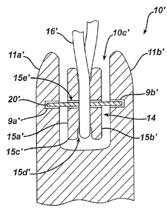
FIG. 2 illustrates one exemplary embodiment of a rotatable suture-engaging
member 14'
that is disposed within an inner lumen 10c' of a suture anchor 10'. As shown,
the suture-
engaging member 14' is in the form of a generally cylindrical body having
opposed
sidewalls 15a', 15b' and a continuously curved outer wall 15c' extending
therearound and
between the opposed sidewalls 15a, 15b'. A groove 15d' is formed in the outer
wall 15c' for
seating one or more sutures, such as suture 16'. The suture-engaging member
14' also
includes a bore 15e' extending therethrough between the opposed sidewalls
15a', l5b' for
receiving a pin member 20' that allows the suture-engaging member 14' to
rotate
therearound. The pin member 20' can extend into opposed bores or openings 9a',
9b'
formed in an inner surface of the opposed arms 11 a', 11 b' of the suture
anchor 10. A person
skilled in the art will appreciate that a variety of other techniques can be
used to rotatably
mate the suture-engaging member 14' to the suture anchor 10'. Alternatively,
other
techniques can be used to facilitate suture slidability, such as a lubricious
coating applied to
the suture engaging member.
14
CA 02609076 2007-10-31
As previously indicated, the suture anchors disclosed herein can be cannulated
for
receiving a driver. While various drivers known in the art can be used, FIGS.
3A and 3B
illustrate one exemplary embodiment of a driver 30 for driving a suture anchor
into bone.
In this embodiment, the driver 30 is adapted to allow the terminal ends of a
suture(s)
extending through the suture anchor to extend along an external surface
thereof. As shown,
the driver 30 is in the form of a generally elongate shaft having proximal and
distal ends
30a, 30b. While not shown, the proximal end 30a can include a handle or other
grasping
mechanism formed thereon to facilitate grasping and manipulation of the
device. The distal
end 30b includes a reduced diameter portion or tip 32 that is configured to
fit within the
inner lumen of a suture anchor, such as lumen 10c of anchor 10. The shape of
the tip 32 can
vary, but in an exemplary embodiment it has an asymmetrical shape that allows
the tip 32 to
engage the inner lumen I Oc of the anchor 10. In the illustrated embodiment
the tip 32 has a
generally hexagonal cross-sectional shape that complements the generally
hexagonal cross-
sectional shape of the inner lumen l Oc in the anchor. The length of the tip
32 can also vary,
but in an exemplary embodiment the tip 32 has a length that allows it to
extend through a
substantial portion of the lumen l Oc in the anchor 10 so as to maximize
surface contact
between the tip 32 and the anchor 10. For example, the length 32 can
correspond to a
length of the hexagonal portion of the inner lumen l Oc in the anchor. A
person skilled in
the art will appreciate that the tip 32 can have a variety of other shapes,
sizes, and
configurations.
As further shown in FIGS. 3A and 3B, the tip can also include one or more
suture-
receiving recesses or grooves formed therein and extending longitudinally
along the length
of the tip 32 for seating one or more sutures. In the illustrated embodiment
first and second
opposed suture-receiving grooves 34a, 34b are formed in the tip 32 and extend
along the
length thereof. The grooves 34a, 34b can also optionally extend a distance
beyond a
proximal end of the tip 32, as shown, or along the entire length of the driver
30, so as to
further prevent the suture(s) from interfering with insertion of the suture
anchor 10.
FIG. 3C illustrates a cut-away view of the driver 30 disposed within a suture
anchor
100 that is similar to suture anchor 10. As shown, a suture 36 is disposed
through the lumen
100c of the suture anchor 100 and around the suture-engaging member 114 such
that first
and second trailing ends 36a, 36b of the suture 36 extend proximally from the
proximal end
CA 02609076 2007-10-31
100a of the suture anchor 100. In order to allow the distal tip 32 of the
driver 30 to fit
within and engage the inner lumen 100c of the suture anchor 100, the opposed
ends of the
suture 36 extending from the suture-engaging member 14 can be seated within
the opposed
grooves (only one groove 34a is shown) formed in the tip 32.
In another embodiment, as shown in FIGS. 4A and 4B, the driver 40 can be
cannulated to allow the terminal ends of a suture(s) extending through the
suture anchor to
extend therethrough, rather than extending external to the driver. In
particular, the driver 40
is similar to driver 30, except that the driver 40 includes an inner lumen 40c
extending
through the entire length thereof for receiving one or more sutures, rather
than having
suture-receiving grooves formed in the distal tip. FIG. 4A illustrates the
distal tip 42 of the
driver 40 disposed within and engaging the inner lumen l Oc of suture anchor
10. As shown,
the diameter of the remainder of the driver 40 as compared to the reduced-
diameter of the
distal tip 42 can provide a stop surface 44 that limits the depth of insertion
of the distal tip
42 into the inner lumen l Oc of the anchor 10. As previously discussed, the
length of the
distal tip 42, and thus the depth of insertion of the tip 42 into the inner
lumen lOc of the
anchor 10, can vary depending on the size and shape of the suture anchor 10.
In an
exemplary embodiment, the tip 42 is configured to be inserted into a
substantial portion of
the inner lumen I Oc so as to maximum surface contact between the driver 40
and the suture
anchor 10. In other embodiments, the cannulated driver 40 can also optionally
be used to
allow other materials, such as bone-growth promoting materials, adhesives,
biologics, and
other injectable materials, to be introduced through the driver and into the
suture anchor.
16
CA 02609076 2007-10-31
As previously indicated, the suture anchors and drivers disclosed herein can
be
configured for use with one or more sutures. The particular quantity of
sutures used with a
suture anchor and driver can depend on the size of the suture anchor and the
driver, and in
particular on the diameter of the inner lumen of the suture anchor and the
size of the suture-
engaging groove formed in the driver (for driver 30) or the diameter of the
lumen in the
driver (for driver 40). For example, where the suture anchor has a relatively
small inner
lumen, the driver will necessarily have a relatively small diameter and thus
small suture-
engaging grooves (for driver 30) or a small inner lumen (for driver 40). It
may therefore
only be possible to use a single suture that is positioned around the suture-
engaging member
on the suture anchor, and that has two trailing ends extending through the
suture-receiving
grooves in the driver (for driver 30) or through the inner lumen in the driver
(for driver 40).
While a single suture can be sufficient to anchor tissue to bone, it is
preferred to use more
than one, and more preferably two, sutures. Thus, rather than increasing a
size of the suture
anchor andlor the driver, the present invention provides various exemplary
techniques for
utilizing two sutures with a suture anchor and driver that are configured to
seat only one
suture. This is particularly advantageous as the suture anchor can be sized to
be fully
disposed within cortical bone, while the diameter of the inner lumen of the
suture anchor
and of the distal tip of the driver are maximized to increase the torque
failure rating. This
also enables the anchor to be made from a broad range of materials, including
brittle or
weaker materials such as those previously disclosed herein.
In one embodiment, one or more sutures can be coupled to a thin wire, thread,
string,
small diameter suture, etc. (hereinafter generically referred to as a wire),
and the wire can
extend through the suture-receiving grooves or inner lumen in the driver.
Since the wire
will have a diameter that is significantly smaller than a diameter of the
suture, one or more
wires can be used in place of the trailing end of one or mores sutures, thus
allowing multiple
sutures to be used. This is illustrated, by way of non-limiting example, in
FIGS. 5A and 5B.
FIG. 5A illustrates a suture anchor 10 having first and second sutures 16, 18
extending therethrough and around the suture-engaging member (not shown).
Since all four
trailing ends (i.e., the ends extending from the suture-engaging member) of
the sutures 16,
18 will not fit within the suture-receiving grooves in driver 30 (not shown)
or through the
inner lumen of driver 40 (not shown), only one trailing end of each suture 16,
18 can extend
17
CA 02609076 2007-10-31
through the driver and the terminal end 16b, 18b of the other trailing end of
each suture 16,
18 can be positioned just distal to the proximal end of the cut-out 22. A wire
50 can be
mated to each terminal end 16b, 18b and the wire can extend proximally from
the terminal
ends 16b, 18b and through the driver. In use, once the suture anchor 10 is
implanted in
bone, the driver can be removed and the wire 50 can be pulled to pull the
terminal ends 16b,
18b of the sutures 16, 18 proximally around the suture-engaging member and
through the
suture anchor 10. The terminal ends can thereafter be used to secure tissue to
bone. A
person skilled in the art will appreciate that the sutures can remain external
to the driver and
anchor while only the wire(s) extend through the driver and anchor, and the
sutures can be
pulled into the anchor after placement of the suture anchor.
In another embodiment, shown in FIG. 5B, the terminal ends 16b, 18b of the
sutures
16, 18 can be mated to separate wires 52, 54 that extend through the inner
lumen of the
driver. FIG. 5B illustrates a partially cut-away view of the suture anchor 10,
showing the
distal tip 42 of driver 40 disposed therein and having the wires 52, 54
extending
therethrough. As with the embodiment shown in FIG. 5A, one trailing end of
each suture
16, 18 and the wires 52, 54 can extend through the driver 40, thus allowing
two sutures 16,
18 to be used with the anchor 10. After the suture anchor is implanted, the
driver 40 can be
removed and the wires 52, 54 can be used to pull the terminal ends 16b, 18b of
the sutures
16, 18 around the suture-engaging member in a proximal direction, as shown in
FIG. 5C. A
person skilled in the art will appreciate that while FIG. 5B illustrates
driver 40, the wires
can be used with driver 30, or with any other driver known in the art.
The use of wires extending through a cannulated driver can also be
advantageous in
that various materials, such as those previously discussed, can be introduced
through the
inner lumen of the driver with the wires in place. For example, an adhesive
can be injected
through the inner lumen of the driver prior to pulling the terminal ends 16b,
18b of the
sutures 16, 18 proximally, thus allowing the suture 16, 18 to be secured to
the suture anchor
10.
18
CA 02609076 2007-10-31
A person skilled in the art will appreciate that a variety of techniques can
be used to
mate a wire to one or more sutures. By way of non-limiting example, FIGS. 6-10
illustrate
various exemplary mating techniques. In the embodiment shown in FIG. 6, a
single wire 60
is threaded through a terminal end 62a of a first suture 62 and then is
threaded back through
a terminal end 64a of a second suture 64 such that trailing ends 60a, 60b of
the wire 60
extend from the terminal ends 62a, 64a of the sutures 62, 64. In another
embodiment,
shown in FIG. 7, the wire 70 is looped or knotted around the terminal ends
72a, 74a of two
sutures 72, 74 such that trailing ends 70a, 70b of the wire 70 extend from the
terminal ends
72a, 74a of the sutures 72, 74. In the embodiment shown in FIG. 8, the wire 80
is
positioned between two sutures 82, 84 and it is welded to the sutures 82, 84
using an
ultrasonic welder 86, or using other welding techniques known in the art. In
another
embodiment, shown in FIG. 9, a wire 90 can be attached to a clamp or crimp
band 96 that is
disposed around and closed to engage the terminal ends 92a, 94a of two sutures
92, 94. In
yet another embodiment, shown in FIG. 10, the wire 110 can include a spring or
coiled
portion 110c formed on a terminal end thereof. The coiled portion l 10c can be
positioned
around the terminal end 112a of a suture 112, and it can be biased to a shape
in which the
coiled portion 1 l Oc engages the suture 112. When the wire 110 is pulled to
pull the suture
112, the coiled portion 110c can optionally decrease in diameter to provide a
more secure
engagement between the wire 110 and the suture 112. A person skilled in the
art will
appreciate that the aforementioned mating techniques can be used to mate a
single wire to
one or more sutures, or to mate multiple wires to a single suture. Moreover, a
variety of
other mating techniques can be used, including adhesives etc.
In another embodiment, one of the trailing ends of a suture or a wire can be
mated to
the driver. As the driver is removed from the suture anchor, the driver will
pull the suture
or wire attached thereto around the suture engaging member. This is
illustrated in FIGS.
11A and 11B. In the embodiment shown in FIG. 11A, a first end 132a of a wire
132 is
attached to a distal end 130d of a driver 130. The second end 132b of the wire
132 extends
through the suture anchor 10 and proximally from the driver 130, where it can
be coupled to
a suture. The wire 132 can be pulled into the suture anchor 10 and around the
suture-
engaging member 14 as the driver 130 is removed. In another embodiment shown
in FIG.
1 IB, the first end 132a' of the wire 132' can be attached to a proximal end
130p' of the
19
CA 02609076 2007-10-31
I. driver 130'. A person skilled in the art will appreciate that the
particular attachment
location of the wire to the driver can vary. Moreover, a variety of techniques
can be used to
attach a suture or a wire to a driver. By way of non-limiting example, FIG. 11
C illustrates
one exemplary embodiment of an attachment technique. As shown, the distal tip
152 of a
driver includes first and second bores 152a, 152b formed therein, and the
trailing ends of
first and second wires 154, 156 are inserted through the bores 152a, 152b. A
knot is formed
in the terminal end of each wire 154, 156 to retain the wires 154, 156 within
the bores 152a,
152b. In use, instead of having four trailing ends of two sutures extending
through the
driver, only one trailing end of each suture or wire will extend through the
driver while the
other end will remain attached to the distal tip 152. Alternatively, the
trailing ends of two
wires can extend through the driver and attach to sutures positioned external
to the driver.
When the driver is removed, the driver will pull the sutures around the suture-
engaging
member to allow the trailing ends of the sutures to be used to secure tissue
to bone. The
knots can be cut or otherwise removed to detach the sutures from the driver.
In other embodiments, shown in FIGS. 12A-12D, various threading techniques can
be used to allow two sutures to be used with the suture anchors disclosed
herein. FIG. 12A
illustrates suture anchor 10 having two sutures 16, 18 extending through the
inner lumen
l Oc of the suture anchor 10 and looped around the suture-engaging member 14.
Conversely, one of the sutures, e.g., suture 18, can extend along an external
surface of the
suture anchor 10, as shown in FIG. 12B. Similarly, a single suture can be used
and it can
extend through both the inner lumen l Oc of the suture anchor 10, as well as
along an
external surface of the suture anchor 10. This is illustrated in FIG. 12C. As
shown, a first
trailing end 16a of the suture 16 is positioned along an external surface of
the suture anchor
10, and the second trailing end 16b of the suture 16 is threaded around the
suture-engaging
member 14 and up through the inner lumen lOc, where a first loop is formed.
The second
trailing end 16b of the suture 16 is then passed back through the inner lumen
l Oc and
positioned to extend externally along the length of the suture anchor 10.
While FIG. 12C
illustrates both trailing ends 16a, 16b of the suture 16 extending externally
along the suture
anchor 10, in another embodiment one trailing end can extend externally along
the suture
anchor 10 while the other trailing end can extend through the inner lumen l Oc
of the suture
anchor 10. This is illustrated in FIG. 12D, which shows the suture 16 having a
first trailing
CA 02609076 2007-10-31
end 16a extending through the inner lumen l Oc of the suture anchor 10 and
proximally
beyond the proximal end 10a of the suture anchor 10. The second trailing end
16b is passed
through the inner lumen 10, around the suture-engaging member 14, and
externally around
the suture anchor 10. It is then passed back into the proximal end 10a of the
suture anchor
and through the inner lumen 10c, where it is positioned around the suture-
engaging member
14 and externally along the suture anchor 10. A person skilled in the art will
appreciate that
a variety of other threading techniques can be used to allow one or more
sutures to be used
with the various suture anchors and/or drivers disclosed herein.
The present invention also provides exemplary methods for anchoring tissue to
bone. While the method is described in connection with attaching soft tissue
to bone, the
methods and devices disclosed herein can be used in a variety of medical
procedures for
anchoring one structure to another. In general, a bore is formed in bone of a
patient. The
diameter of the bore is preferably slightly less than the largest outer
diameter of the suture
anchor, and the length of the bore it preferably the same as or slightly
greater than a length
of the suture anchor. The bore will extend fully through the cortical bone to
allow the
suture anchor to be fully engaged through the thickness of the cortical bone.
The bore can
also extend into the cancellous bone depending on the length of the suture
anchor. One or
more sutures (including sutures with wires coupled thereto) can be coupled to
the suture
anchor using various techniques, as previously discussed herein, and the
distal tip of a
driver can be inserted into the lumen in the suture anchor. The trailing ends
of the suture(s)
or wire(s) can extend externally along the driver or they can extend through
an inner lumen
of the driver. The driver can then be used to insert the suture anchor into
the bone tunnel.
For example, where the suture anchor includes threads formed thereon, the
driver can be
rotated to thread the suture anchor into the bone hole. The threads will
engage the bone
hole thereby preventing removal of the suture anchor. In other embodiments,
the driver can
be used to tap the bone anchor into the bone hole, and an interference fit,
compression fit,
and/or surface features, such as ribs or protrusions, formed on the suture
anchor can be used
to retain the suture anchor within the bone hole. The driver can also
optionally be used to
impact a threaded suture anchor into the bone hole. The threads can allow for
later removal
of the suture anchor.
Once the bone anchor is properly anchored within the bone hole, various
materials,
21
CA 02609076 2007-10-31
4 '
such as those previously discussed herein, can be introduced through the
driver and into or
around the suture anchor. The driver can then be removed. Where the suture(s)
have
wire(s) attached thereto, the wire(s) can be pulled to pull the suture(s)
around the suture-
engaging member of the suture anchor. If the suture anchor includes a
rotatable suture-
engaging member, the suture-engaging member will rotate as the suture(s) is
pulled
therearound. The trailing ends of the suture(s) can then be used to anchor
soft tissue to the
bone. For example, one or both trailing ends of the suture(s) can be attached
to a needle to
allow the needle to be used to thread the suture through tissue to be anchor
to the bone. The
suture(s) can be threaded through tissue either prior to or after insertion of
the suture anchor
into bone. Once the soft tissue is approximated toward the bone, the trailing
ends of the
suture(s) can be secured together and the excess trimmed as is typical in
these situations to
complete the surgery.
One skilled in the art will appreciate further features and advantages of the
invention
based on the above-described embodiments. Accordingly, the invention is not to
be limited
by what has been particularly shown and described, except as indicated by the
appended
claims. All publications and references cited herein are expressly
incorporated herein by
reference in their entirety.
22