Note: Descriptions are shown in the official language in which they were submitted.
CA 02616136 2008-01-22
WO 2007/014104 PCT/US2006/028552
SYSTEM AND METHOD OF EVALUATING DOSE DELIVERED BY A
RADIATION THERAPY SYSTEM
RELATED APPLICATIONS
[0001] This application claims the benefit of U.S. Provisional Patent
Application No.
60/701,588; titled SYSTEM AND METHOD OF DETERMINING POSITION OF AN
OBJECT AND DELIVERING RADIATION THERAPY TREATMENT; filed on July 22,
2005; and the benefit of U.S. Provisional Patent Application No. 60/701,580;
filed July 22,
2005; titled SYSTEM AND METHOD FOR FEEDBACK GUIDED QUALITY
ASSURANCE AND ADAPTATIONS TO RADIATION THERAPY TREATMENT; both of
which are incorporated herein by reference.
BACKGROUND
[0002] Over the past decades, improvements in coinputers and networking,
radiation
therapy treatment planning software, and medical imaging modalities (CT, MRI,
US, and
PET) have been incorporated into radiation therapy practice. Often, devices
are used to track
the motion and position of the equipment that is used to deliver a treatment.
The amount of
radiation that is delivered to a patient during a treatment is also monitored
in order to deliver
the correct dose (e.g., amount of radiation) to the appropriate target
treatment area.
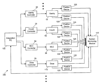
Typically, equipment and patient position information is gathered via
mechanical sensors that
are hard-wired to control computers.
SU1VIlMARY
[0003] In one embodiment, the invention provides a local positioning system
("LPS"), to
control, verify, synchronize, and/or QA radiation therapy treatment systems or
imaging
device systems. This can be done in real-time or as a post-process. An aspect
of the
invention includes an interface between the LPS and other positioning systems,
and the use of
this information for machine control, synchronization, and/or patient
procedures, such as
imaging or therapy. In another aspect, the LPS can communicate with other
patient
monitoring devices to acquire information to use for machine control,
synchronization, and/or
patient procedures.
[0004] Another embodiment of the invention includes a method for tracking
different
hardware components in the context of patient imaging or treatment. These
components can
1
CA 02616136 2008-01-22
WO 2007/014104 PCT/US2006/028552
include gantries, couches, collimators (both the base and/or individual
leaves) or other
components for which feedback is desired. Sensors for this system could also
be affixed to
patients.
[0005] One method of positioning feedback utilizes mechanical sensors that are
typically
hard-wired to control computers. Other methods of feedback focus on patient
monitoring,
and these include implantable RF devices that can be inserted into the
patient. Some of these
devices use MOSFET technology to provide feedback on dose received, while
others provide
readout of location.
[0006] In another embodiment, the invention provides a radiation imaging
and/or
therapy-treatment system. The system comprises a radiation source, a movable
apparatus, a
controller configured to control, including moving, the movable apparatus, and
a local
positioning system. The local position system includes a position verification
device directly
coupled to the movable apparatus and a system monitoring module in
communication with
the position verification device. The local positioning system is configured
to detennine
position data for the position verification device.
[0007] In another embodiment, the invention provides a method of evaluating
dose
delivered by a radiation therapy system using a marker that indicates motion.
The marker is
associated with the patient. The method comprises the acts of delivering
radiation to the
patient, monitoring motion of the marker during the delivering radiation, and
evaluating a
dose delivered to the patient based at least in part on the motion of the
marker.
[0008] In another embodiment, the invention provides a method of evaluating
dose
delivered by a radiation therapy system using a marker associated with the
patient. The
method comprises the acts of delivering radiation to the patient, obtaining
information
relating to the delivery of radiation, estimating dose to the marker based at
least in part on the
information, acquiring dose received by the marker, and comparing the received
dose with
the estimated dose.
[0009] In another embodiment, the invention proves a method of evaluating dose
delivered by a radiation therapy system using a marker that indicates motion.
The marker is
associated with the patient. The method comprises the acts of delivering
radiation to the
patient, monitoring motion of the marker during the delivering radiation,
estimating a dose
2
CA 02616136 2008-01-22
WO 2007/014104 PCT/US2006/028552
delivered to the patient based at least in part on the motion of the marker,
acquiring dose
received by the marker, and comparing the received dose with the estimated
dose.
[0010] Other aspects of the invention will become apparent by consideration of
the
detailed description and accoinpanying drawings.
BRIEF DESCRIPTION OF THE DRAWINGS
[0011] FIG. 1 is a partial perspective view, partial schematic illustration of
a radiation
therapy treatment system according to one embodiment of the invention.
[0012] FIG. 2 is a partial perspective view, partial schematic illustration of
a multi-leaf
collimator that can be used in the radiation therapy treatment system
illustrated in FIG. 1.
[0013] FIG 3 schematically illustrates a local positioning system according to
one
embodiment of the invention and incorporated with the radiation therapy
treatment system of
FIG. 1.
[0014] FIG 4 is a block diagram of a plurality of devices that can be used in
the local
positioning system of FIG. 3.
[0015] FIG. 5 is a flow chart of a method of delivering a radiation therapy
treatment that
utilizes variable intensity seeds according to one embodiment of the
invention.
[0016] FIG. 6 is a flow chart of a method of utilizing feedback from a MOSFET
type
marker implanted in, or near a target according to one embodiment of the
invention.
DETAILED DESCRIPTION
[0017] Before any embodiments of the invention are explained in detail, it is
to be
understood that the invention is not limited in its application to the details
of construction and
the arrangement of components set forth in the following description or
illustrated in the
following drawings. The invention is capable of other embodiments and of being
practiced
or of being carried out in various ways. Also, it is to be understood that the
phraseology and
terminology used herein is for the purpose of description and should not be
regarded as
limiting. The use of "including," "comprising," or "having" and variations
thereof herein is
meant to encompass the items listed thereafter and equivalents thereof as well
as additional
items. Unless specified or limited otherwise, the terms "inounted,"
"connected,"
3
CA 02616136 2008-01-22
WO 2007/014104 PCT/US2006/028552
"supported," and "coupled" and variations thereof are used broadly and
encompass both
direct and indirect mountings, connections, supports, and couplings. Further,
"connected"
and "coupled" are not restricted to physical or mechanical connections or
couplings.
[0018] Although directional references, such as upper, lower, downward,
upward,
rearward, bottom, front, rear, etc., may be made herein in describing the
drawings, these
references are made relative to the drawings (as normally viewed) for
convenience. These
directions are not intended to be taken literally or limit the invention in
any form. Iil
addition, terms such as "first", "second", and "third" are used herein for
purposes of
description and are not intended to indicate or iniply relative importance or
significance.
[0019] In addition, it should be understood that embodiments of the invention
include
hardware, software, and electronic components or modules that, for purposes of
discussion,
may be illustrated and described as if the majority of the components were
implemented
solely in hardware. However, one of ordinary skill in the art, and based on a
reading of this
detailed description, would recognize that, in at least one embodiment, the
electronic based
aspects of the invention may be implemented in software. As such, it should be
noted that a
plurality of hardware and software based devices, as well as a plurality of
different structural
components may be utilized to implement the invention. Furthermore, and as
described in
subsequent paragraphs, the specific mechanical configurations illustrated in
the drawings are
intended to exemplify embodiments of the invention and that other alternative
mechanical
configurations are possible.
[0020] FIG. 1 illustrates a radiation therapy treatment system 10 that can
provide
radiation therapy to a patient 14. The radiation therapy treatment can include
photon-based
radiation therapy, brachytherapy, electron beam therapy, proton, neutron, or
particle therapy,
or other types of treatment therapy. The radiation therapy treatment system 10
includes a
radiation therapy device having a gantry 18 controlled by to a gantry
controller 20. Though
the gantry 18 shown in the drawings is a ring gantry, i.e., it extends through
a fu11360 arc to
create a complete ring or circle, other types of mounting arrangements may
also be employed.
For example, a C-type, partial ring gantry, or robotic arm could be used.
[0021] The gantry 18 can support a radiation module, having a radiation source
22 and a
linear accelerator 26 operable to generate a beam 30 of photon radiation. The
radiation
module can also include a modulation device 34 operable to modify or modulate
the radiation
4
CA 02616136 2008-01-22
WO 2007/014104 PCT/US2006/028552
beam 30. The modulation device 34 provides the modulation of the radiation
beam 30 and
directs the radiation beam 30 toward the patient 14. Specifically, the
radiation beam 30 is
directed toward a portion of the patient. Broadly speaking, the portion may
include the entire
body, but is generally smaller than the entire body and can be defined by a
two-dimensional
area and/or a three-dimensional volume. A portion desired to receive the
radiation, which
may be referred to as a target or target region (shown as 46), is an example
of a region of
interest. Another type of region of interest is a region at risk. If a portion
includes a region at
risk, the radiation beam is preferably diverted from the region at risk. The
patient 14 may
have more than one target region 46 that n.eeds to receive radiation therapy.
Such modulation
is sometimes referred to as intensity modulated radiation therapy ("IMRT").
[0022] Other frameworks capable of positioning the radiation module at various
rotational and/or axial positions relative to the patient 14 may also be
employed. In addition,
the radiation source 22 may travel in path that does not follow the shape of
the gantry 18. For
example, the radiation source 24 may travel in a non-circular path even though
the illustrated
gantry 18 is generally circular-shaped.
[0023] In one construction, and illustrated in FIG. 2, the modulation device
34 includes a
collimation device. The collimation device includes the primary collimator
having a set of
jaws 39. The jaws define and adjust the size of an aperture 40 through which
the radiation
beam 30 may pass. The jaws 39 include an upper jaw and a lower jaw controlled
by an
actuator 41. The upper jaw and the lower jaw are moveable to adjust the size
of the aperture
40. The collimation device further includes a multi-leaf collimator (MLC) 38,
which
includes a plurality of interlaced leaves 42 operable to move from position to
position. The
movement of the leaves 42 and jaws 39 can be tracked with positioning devices
(as described
in greater detail below). It is also noted that the leaves 42 can be moved to
a position
anywhere between a minimally and inaximally-open position. The plurality of
interlaced
leaves 42 modulates the strength, size, and shape of the radiation beam 30
before the
radiation beam 30 reaches the target 46 on the patient 14. Eacli of the leaves
42 is
independently coiitrolled by an actuator 50, sucll as a motor or an air valve
so that the leaf 42
can open and close quickly to permit or block the passage of radiation. The
actuators 50 can
be controlled by a MLC computer and/or controller 54.
[0024] The radiation therapy treatment system 10 (Fig. 1) can also include a
detector 58
(e.g., a kilovoltage or a megavoltage detector) operable to receive a
radiation beam from the
CA 02616136 2008-01-22
WO 2007/014104 PCT/US2006/028552
treatment radiation source 22 or fiom a separate radiation source. The linear
accelerator 26
and the detector 58 can also operate as a computed tomography ("CT") system to
generate
CT images of the patient 14. The linear accelerator 26 emits the radiation
beam 30 toward
the target 46 in the patient 14. The CT images can be acquired with a
radiation beam 30 that
has a fan-shaped geometry, a multi-slice geometry, or a cone-beam geometry. In
addition,
the CT images can be acquired with the linear accelerator 26 delivering
megavoltage energies
or kilovoltage energies. The target 46 and surrounding tissues absorb some of
the radiation.
The detector 58 detects or measures the ainount of radiation absorbed by the
target 46 and the
surrounding tissues. The detector 58 collects the absorption data from
different angles as the
linear accelerator 26 rotates around and emits radiation toward the patient
14. The collected
absorption data is transmitted to the computer 54 to process the absorption
data and to
generate cross-sectional images or "slices" of the patient's body tissues and
organs. The
images can also illustrate bone, soft tissues and blood vessels.
[0025] The radiation therapy treatment system 10 can also include a patient
support, such
as a couch 62 (illustrated in Fig. 1), which supports the patient 14. The
couch 62 moves
along at least one axis in the x, y, or z directions. In other constructions,
the patient support
can be a device that is adapted to support any portion of the patient's body,
and is not limited
to having to support the entire patient's body. The system 10 also can include
a drive system
66 operable to manipulate the position of the couch 70. The drive system 66
can be
controlled by a couch computer and/or controller 70. Alternatively, the drive
system 66 can
be controlled using another computer and/or controller of the treatment system
10.
[0026] The radiation therapy treatment system 10, as described above, includes
many
components and mechanisms (e.g., the couch 62, the MLC 38, the gantry 18,
etc.) that can
move from one position to another in order to deliver a desired dose (e.g., a
predeterinined
amount of radiation) to the patient 14. For example, the leaves 42 of the MLC
38 can move
in order to modulate the intensity of radiation that is being delivered to the
patient 14.
Additionally, the couch 62 can move in order to properly position the target
46. The motion
of each of the components of the treatment systezn 10, therefore, can be
precisely controlled
to deliver the proper dose to the patient 14. The motions (as well as
operations) of the
components and mechanisms of the treatment system 10 can be controlled with a
plurality of
computers and/or controllers (e.g., the gantry controller 20, the couch
controller 70, the MLC
controller 54, etc.). Other controllers, such as a dose controller 75 (shown
in FIG. 3), can
6
CA 02616136 2008-01-22
WO 2007/014104 PCT/US2006/028552
also be iinplemented to deliver the proper dose to the patient 14 during the
treatinent. The
dose controller 75 can receive signals from a plurality of positioning and
dose verification
devices (as described in greater detail below) in order to detennine the
proper dose that is to
be delivered to the patient 14.
[0027] Alternatively, a single system computer (not shown) can be used to
control the
entire treatment system 10, which incorporates the processes and operations of
all of the
separate controllers and/or computers.
[0028] FIG. 3 illustrates an embodiment of a LPS 100, having links to multiple
radiation
therapy treatment system components, as well as their respective controllers.
The LPS 100
can also be used to track the movement of the patient 14 and target 46 (as
described with
respect to FIG. 4). In other embodiments, the LPS 100 can be implemented in
other types of
imaging equipment (e.g., CT, MRI, PET, etc.), and is not limited to the
radiation therapy
treatment system 10 that is shown in FIG. 1. In the embodiment shown in FIG.3,
the LPS
100 includes an integration computer 105, a system monitoring module 110, and
a plurality
of position verification devices 125.
[0029] Before proceeding further, it should be understood that the plurality
of position
verification devices 125 may also be referred to herein as the plurality of
motion verification
devices 125. As discussed herein, the position verification devices 125 can be
used to
acquire a velocity (or speed), an acceleration, or a time series for the
devices 125. The
position information, velocity information, acceleration information, and time
series
information can be collectively referred to herein as motion information,
hence the possible
use of the term "motion verification device" in alternative to "position
verification device."
Also as discussed herein, the position verification devices 125 (or motion
verification devices
125) can be used to monitor radiation to the position verification devices
125.
[0030] As shown in FIG. 3, each of the controllers of the treatment system 10
(e.g., the
gantry controller 20, the couch controller 70, the MLC controller 54, the dose
controller 75,
etc.) can transmit signals to each of their respective treatment system
components in order to
control their motion and operation. It should be understood that signals, such
as those being
received and transmitted in FIG. 3, can be sustained with wired and wireless
communication
components (e.g., a copper wire, a coaxial cable, a radio frequency ("RF"), an
infrared ("IR")
signal, a Wi-Fi signal, etc.). The treatment system components also transmit
signals to the
7
CA 02616136 2008-01-22
WO 2007/014104 PCT/US2006/028552
system monitoring module 110. Those signals can correspond to the actual
position and
operation of the components. The system monitoring module 110 can also receive
signals
from the position verification devices 125.
[0031] Referring still to FIG. 3, the position verification devices 125 of the
LPS 100 can
be coupled to various components of the treatment system 10. The position
verification
devices 125 can be used to gather relative and absolute position data from the
components of
the treatment system 10, which can aid in optimizing the delivery of a
radiation therapy
treatment. For example, a position verification device 125 can be coupled to
the couch 62 to
provide a position, speed, and/or sag of the couch 62. As other examples, the
position
verification devices 125 can be strategically located to detect gantry
position, speed, and sag
and leaf position and speed.
[0032] The position verification device 125 can also supply position data that
is relative
to other components, for example, the couch position relative to the gantry
position. '
Similarly, position verification devices 125 can be coupled to various other
components (e.g.,
the leaves 42 of the MLC 38, the gantry 18, the linear accelerator 26, etc) of
the treatment
system 10 in order to provide other position data. Additionally, in some
embodiments,
positioning devices and beacons can be coupled to, or implanted in patients 14
to provide
patient 14 and target position information (as described in greater detail
with respect to FIG.
4).
[0033] In some embodiments, the LPS 100 can also be used to track the speed at
which
the components of the treatment system 10 are moving. More specifically, the
speed of the
components can be determined in a variety of methods by using the signals of
the position
verification devices 125. In one embodiment, the Doppler Effect is used to
track the speed of
each of moving components. In another einbodiment, a position/time comparison
calculation
can be completed to determine the speed of each component of the treatment
system 10. For
example, the speed with which the linear accelerator 26 moves from one
position to another
around the gantry 18 can be tracked using the Doppler Effect by tracking a
position
verification device 125 fixed to the linear accelerator.
[0034] In order to track the position and speed of each of the verification
devices 125, the
signals that are received by the system monitoring module 110 are relayed to
the integration
coinputer 105. In some embodiments, the signals that are transmitted to the
integration
8
CA 02616136 2008-01-22
WO 2007/014104 PCT/US2006/028552
computer 105 from the system monitoring module 110 are relayed directly and
without
alteration. In other embodiments, the signals that are transmitted from the
system monitoring
module 110 to the integration computer 105 are modulated or altered prior to
being sent.
Alternatively, the system monitoring module 110 can be incorporated directly
into the
integration computer 105.
[0035] Upon receiving the signal.s from the systein monitoring module 110, the
integration computer 105 can complete the control loop that is created by the
LPS 100, and
transmit signals back to each of the plurality of system controllers (i.e.,
the gantry controller
20, the couch controller 70, the MLC controller 54, the dose controller 75,
etc.). The signals
that are transmitted from the integration computer 105 to each of the system
controllers can
then be used to alter the position and operation of the system components.
Therefore, the
integration computer 105 can effectively control the entire treatment system
10.
[0036] In one embodiment, the integration computer 105 of the LPS 100 can be
used to
compare the signals (e.g., motion signals such as position signals, velocity
signals,
acceleration signals, etc.) of each of the treatinent system components to the
signals of the
position verification devices 125. For example, the position signal of a
position verification
device 125 that is coupled to the couch 62 can be cross-checked with a hard-
wired position
signal that is transmitted directly from the couch 62. If the position
verification device signal
differs from the signal produced by the couch 62, the integration computer 105
can determine
if an alteration to the couch position needs to be made. The integration
computer 105 can
then transmit a correction signal to the couch controller 70 in order to move
the couch 62 to
the proper position.
[0037] In another embodiment, the speed of a component can be corrected with
the LPS
100 using the integration computer 105. For example, the speed that is
monitored with the
position verification devices 125 can be compared to a speed signal that is
produced from a
hard-wired component of the linear accelerator 26. If the speed that is
monitored with the
position verification device 125 differs from that of a hard-wired connection,
an alteration to
the motion of the linear accelerator 26 can be made using the integration
computer 105.
[0038] The LPS 100, therefore, can be used to gather a plurality of
information from
components of the treatment system 10 in order to temporally and spatially
monitor and
correct the motion of each component using absolute and relative reference
points. In doing
9
CA 02616136 2008-01-22
WO 2007/014104 PCT/US2006/028552
so, each of the components of the treatment system 10 that are being tracked
by the position
verification devices 125 can be coordinated and synchronized with eacll other
to deliver the
proper dose and treatment to the patient 14. For example, the couch 62, the
linear accelerator
26, and the MLC 42 can all be synchronized, and have their motions verified in
real-time by
the integration computer 105 to deliver a treatment to the patient 14.
Corrections to speed
and position of the coinponents of the treatment system 10 can be made as
needed.
[0039] In another embodiment, the LPS 100 and/or other object positioning
systems can
interface and/or communicate with the treatment system 10 to conduct post-
processing
verification operations. It is noted that patient monitoring devices could
also interface and/or
communicate with the treatment system 10 to perform post-processing
verification
operations. After a treatment is completed, the signals of the position
verification devices
125 can be reviewed. The hard-wired signals of each of the conlponents of the
treatment
systein 10 can also be reviewed. The signals from the position verification
devices 125 can
then be compared to the corresponding hard-wired signals. The results of the
coinparison can
be used as a quality assurance check to verify that all of the components of
the treatinent
system 10 have operated correctly. Faulty components and components that need
to be
replaced can potentially be identified using this comparison.
[0040] The position verification devices 125 (described above) of the LPS 100
are not
limited to inonitoring mechanical devices and components (i.e., the gantry 18,
the MLC 38,
the couch 62, etc.). Also, the verification aspects of this invention are not
limited to the LPS
devices described above. In another embodiment, a plurality of position
monitoring devices
can be coupled to, or implanted in the patient 14 in order to monitor, detect,
and/or alter the
dose 115 that is delivered during a treatment. FIG. 4 illustrates a group 200
of exemplary
position devices that can aid in the delivery of a radiation therapy
treatment. The position
devices can include a reflector marker 205, a transmitter marker 210, a
variable intensity seed
215, aiid a transistor marker 220. Other types of position devices can include
a radio-
frequency seed and a variable frequency seed. Each of the position devices
included in the
group 200 can be incorporated into the LPS 100. In other embodiments, the
position devices
205-220 need not be included in the LPS 100, and can be implemented in a
separate, stand-
alone monitoring system. Before proceeding further, it should be understood
that the term
"inarker" is used broadly herein to encompass the terin seed. For example, the
variable
intensity seed 215 may also be referred to herein as the variable intensity
marker 215.
CA 02616136 2008-01-22
WO 2007/014104 PCT/US2006/028552
[0041] In some embodiments, reflector markers 205 are implanted near the
target 46 of a
patient 14, and used as a passive tracking and positioning beacon. The
reflector markers 205
can also be positioned in a location that approximates the patieilt 14 (such
as the couch 62).
When the reflector marker 205 is excited by a trigger source, such as a
radiation source, the
position of the reflector marker 205 can be used to "localize" the position of
the target 46. In
some einbodiments, the reflector markers are used in combination with CT
imaging prior to,
or during radiation treatment. The position data that is gained using the
reflector markers 205
can confirm the patient 14 and target 461ocations with respect to the
patient's anatomy.
Therefore, the reflector inarkers can aid in directing the radiation therapy
treatment toward
the target 46. The reflector markers 205 can also be implanted in (or
positioned near) other
areas of the patient 14. For example, markers 205 can be implanted near an
identified region
at risk ("RAR") in order to avoid exposing a particularly vulnerable area to
radiation.
[0042] Transmitter markers 210 are another type of localizer, and can be used
similarly to
the reflector markers 205. However, the transmitter markers 210 do not require
a trigger
source to be activated. Therefore, depending on the configuration, the
transmitter marker 210
can be located at any time during a treatment (and not only when the patient
is being exposed
to radiation). Transmitter markers 210 can transmit a variety of signals
(e.g., RF, Bluetooth,
WiFi, IEEE 802.15.4, and the like), which are received by a corresponding
receiver.
[0043] In another embodiment, variable intensity seeds 215 can be used to
track both the
position of the patient 14 and the dose that is delivered to the patient 14.
For example, an RF
localization seed can be configured to produce a specific signal, which
corresponds to a
certain predetermined dose that is to be delivered to the patient 14. The
configured RF seed
can then be implanted into or near the target 46 of the patient 14. Each time
the RF seed is
exposed to a radiation treatment, the RF signal that is transmitted from the
seed can become
weaker. After the entire predetermined dose has been delivered, the seed will
stop
transmitting signal.
[0044] For radiation treatinents that require multiple delivery sessions, the
variable
intensity seeds 215 can be probed for information prior to every treatment. In
doing so, the
amount of radiation that has been delivered to the patient prior to that
delivery session can be
verified. Additionally, the amount of radiation that has been received by the
seed 215 can be
verified with the amount of radiation that has been delivered by the treatment
system 10.
Those values can then be compared, and the operation of the treatment system
10 can be
11
CA 02616136 2008-01-22
WO 2007/014104 PCT/US2006/028552
verified. In other embodiments, the seeds 215 can transmit their variable
signal using a
plurality of other techniques (including wireless and wired connections), such
as WiFi,
signals included in the IEEE 802.15 family, fiber optic connections, or
traditional wire
connections. Additionally, the seeds 215 can be varied in alternative ways in
order to
determine the dose that is delivered to the patient 14. For example, in some
embodiments,
the signal that is transmitted from the seeds 215 can increase, or get
stronger, according to the
amount of radiation that is received.
[0045] In some embodiments, the variable intensity seeds 215 can aid in
determining
deformation of the target 46 (e.g., how the target 46 reacts to the radiation
treatment). For
example, the markers, such as the variable intensity seeds 215, can be used as
fiduciary points
for defortnation calculations. Deformation calculations can be made initially
using a CT
image, or by tracking the target 46 with one or more markers. An example
deformation
calculation is described in U.S. Provisional Patent Application No.
60/701,580; filed July 22,
2005; titled SYSTEM AND METHOD FOR FEEDBACK GUIDED QUALITY
ASSURANCE AND ADAPTATIONS TO RADIATION THERAPY TREATMENT, the
entire content of which is incorporated herein by reference. The deformation
of the target 46
can then be compared to the amount of radiation that is delivered to the
patient 14, which can
be calculated using the seeds 215. Radiation treatment strategies may be
altered according to
the amount of radiation that is received when compared to the amount of
deformation that has
occurred.
[0046] FIG. 5 illustrates a flow chart of a method of delivering a radiation
therapy
treatment that utilizes variable inteiisity seeds 215. The patient 14 is first
registered by the
treatinent systeni 10 (block 250). To do so, the variable intensity seeds 215
can transmit
registration signals that are unique to the patient 14 and the target 46,
wlzich can help ensure
that the correct treatment is being delivered. Once registered, the dose that
is to be delivered
to the patient 14 can be determined (block 255). The intensity of the signal
that is being
transmitted from the seed(s) 215 may be adjusted according to the dose that is
determined.
The amount.of radiation that is delivered in a dose can depend on the patient
14, the target 46,
and the deformation of the target 46. After determining the dose that is to be
delivered to the
patient 14, the position of the target 46 can be determined (block 260). In
some
embodiments, the signal that is being transmitted from the seed 215 can be
used to calculate
the position of the target 46. In other einbodiinents, markers (such as
markers 205 and 210)
12
CA 02616136 2008-01-22
WO 2007/014104 PCT/US2006/028552
can be used to determine the location of the target 46. Additionally, the
positions of other
areas (e.g., the position of the patient's body on the couch 62) can also be
tracked, as
described above.
[0047] Once the position data has been collected, the predetermined dose can
be
delivered to the patient 14 (block 265). During delivery, the seeds 215 can be
used to
calculate the dose that is being received by the patient 14 (block 270). In
some embodiments,
the signal that is being transmitted from the seeds 215 is tracked
continuously so that the
amount of radiation that is being received by the patient can be tracked
throughout a
treatment. In other embodiments, the signal from the seeds 215 is read or
polled at
predetermined intervals. In order to verify that the correct dose is being
received by the
patient, the dose that is being delivered can be compared to the dose that is
being received
according to the seed 215 (block 275). If the amount of radiation that is
being received by
the patient 14 is relatively equal to the amount of radiation that is being
delivered, a
determination can be made whetller or not to continue the treatinent (block
280). The
treatment can be ended (block 285) if the signal from the seed 215 is no
longer present.
However, if additional treatmeiit is required, the process can return to block
255 in order to
determine the proper dose to be delivered to the patient 14.
[0048] Referring again to block 275, if the amount of radiation that is being
received by
the patient 14 is not relatively equal to the amount of radiation that is
being delivered by the
treatment system 10, a determination whether or not to continue the treatment
can be made
(block 290). In some embodiments, a difference between the amount of radiation
that is
delivered to the patient 14 and the amount of radiation that is received by
the patient 14 can
signal a treatment system malfunction. Such a discrepancy may also be an
indication that the
improper area is being treated. In such embodiments, the treatinent may be
terminated (block
295). However, in some einbodiments, adjustments can be made to alter the dose
that is
delivered, change position of the components of the treatment system 10, or
change the
position of the patient 14 (block 300). Such alterations can correct the
delivery of the
treatment so that the delivery can continue. After adjusting the necessary
components, the
process can return to block 255 so that the dose calculation can be completed
for the
subsequent delivery. An example dose calculation is also described in U.S.
Provisional
Patent Application No. 60/701,580.
13
CA 02616136 2008-01-22
WO 2007/014104 PCT/US2006/028552
[0049] In one embodiment, the process shown in FIG. 5 can be carried out using
the dose
controller 75 (illustrated in FIG. 3) that is included in the LPS 100. In
another embodiment,
the process shown in FIG. 5 can be implemented using a separate, stand-alone
system. The
speed with which the process steps are completed can depend on the
capabilities of the
systein that is completing it. In some embodiments, the process is virtually
continually
updated so that the treatment system alterations to the dose and delivery can
be made during a
treatment.
[0050] Referring back to FIG. 4, transistor markers 220 can also be used to
track the
position of the patient 14, and the dose that is received by the patient 14.
However, unlike
the variable intensity seeds 215, the signal of the transistor markers 220 can
be used to
monitor the intensity of the dose, as well as the amount of radiation that has
been received by
the patient. More specifically, the intensity signals from the transistor
markers 220 can be
coinpiled to provide an indication of the dose that has been received by the
patient 14.
[0051] In one einbodiinent, a metal-oxide-semiconductor field effect
transistor
("MOSFET") marker 220, such as sensors or markers from Sicel Technologies,
Inc. in
Morrisville, North Carolina, can be used in combination with other localizer
markers (such as
markers 205 and 210) to aid in the optimized delivery of a dose to the patient
14. The
localizer markers can be used to determine the location and deformation
characteristics of the
target 46, and the MOSFET marker 220 can be used to monitor the dose that is
being
received by the patient 14. The dose that is received by the patient 14, and
tracked by the
MOSFET marker 220, can then be compared to the dose that is actually delivered
from the
treatment system 10. The comparison of doses after a treatment can be used to
detect
systematic or random errors in treatment, and prepare for future reinedial
treatments or
treatment modification. In other embodiments, the dose can be monitored by the
MOSFET
marker 220 throughout the treatment in real-time, and alterations can be made
to the delivery
strategy during the same treatment.
[0052] FIG. 6 illustrates a flow chart of a method of utilizing feedback from
a MOSFET
type marker 220 implanted in, or near the target 46. In the embodiment shown
in FIG. 6, the
process is completed in combination with a daily CT scan, which is completed
prior to the
treatment being delivered. However, in otller embodiments, the markers 220 can
be used at
any time prior to, during, or after the treatment, and in combination with a
variety of other
treatments (MRI, PET, etc.).
14
CA 02616136 2008-01-22
WO 2007/014104 PCT/US2006/028552
[0053] As shown in FIG. 6, the location of the markers 220 is first detennined
(block
350). Other beacons and seeds (e.g., the markers 205-215) can also be located
to provide a
complete set of positional data for the patient 14 and target 46. After
locating the markers
205-220, a comparison of their current location can be made to the marker
location of past
treatments (block 355). In doing so, a migration of the marker 220 (if any)
can be tracked.
The marker 220 may migrate from one location to another due to outside forces
or movement
of the target 46. In either case, adjustinent may be required if the marker
has substantially
migrated from one position to another in subsequent treatments. After
determining the
position of the marker (block 355) the dose that has been delivered by the
treatnlent system
can be recorded, and the predicted amount of radiation that was actually
received by the
patient 14 can be calculated (block 360). The amount aild intensity of
radiation that has
actually been received by the marker 200 can also be measured (block 365).
[0054] The predicted dose calculation (block 360) can be compared to the dose
that was
monitored with the marker 220 (block 365) in order to verify that the dose
that was received
was equal or near to the dose that was delivered (block 370). After
determining whether or
not the treatment that was delivered to the patient 14 was equal to the
treatment that was
received by the patient 14 (block 370) the location of the target 46 can be
considered (block
375). The conduciveness of a target 46 to be treated by radiation therapy can
vary throughout
the body. Therefore, in some cases, the amount of radiation that is delivered
by the treatment
system 10 can be greater than the dose that is received by the target 46. A
report can be
generated (block 380) that can indicate, based on prior knowledge of a target
46 and past
treatments, the dose that should be received by the patient for a particular
delivery. The
deformation effects that are likely to occur can also be considered. Using the
information of
the certainty report and the dose data from the marker 220, the decision can
be made whether
or not a subsequent treatment is required (block 385). Using the markers 220
in this way can
improve deformation calculations and validate projected deformation maps. The
process
ends if subsequent treatments are not needed (block 390). If another treatment
is needed, the
settings of the treatment system 10 can be adjusted (block 395) and the
process can return to
block 360. The position of the components of the treathnent system 10 and the
dose that is
delivered may need to be adjusted based on the type of treatment, deformation,
or patient
position.
CA 02616136 2008-01-22
WO 2007/014104 PCT/US2006/028552
[0055] Referring back to FIG. 4, in another embodiment, a set of markers and
seeds of
the group 200 can be chosen and used to deliver a treatment to a target 10
that is in motion
(e.g., a lung, a digestive tract, etc.). The combination of inarkers and seeds
205-220 that are
chosen from the group 200 can be determined according to treatment system 10,
the type of
treatment that is being delivered, and the patient 14.
[0056] In one embodiment, the motion of the target 46 can be tracked using
both the
group 200 of markers and seeds, as well as with other devices (e.g.,
fluoroscopy, MVCT,
kVCT, and the like). Then, during the delivery of a dose the treatment can be
adapted or
interrupted depending on the position of the target. For example, the lung of
a patient 14 may
need to be radiated. Due to the patient's need to breathe during treatment,
the target 46 (i.e.,
the lung) may be in relatively constant motion. To track the motion of the
lung, markers and
seeds of the group 200 can be implanted in, or positioned proximate to the
lung. The motion
of the lung can also be monitored by other devices, such as those listed
above. By tracking
the motion of the lung the treatment that is being delivered can be adapted to
include different
doses according to the type of motion that is occurring. More specifically,
the dose that is
being delivered when the patient is breathing in may be different from the
dose that is being
delivered when the patient is breathing out. Additionally, the motion of the
lung and the
treatment that is delivered can be verified by comparing the signals of the
markers and seeds
of the group 200 to the signals of the other devices. If the results of the
comparison are not
consistent with each other, an error in treatment or an equipment malfunction
can be
identified. Erratic behavior of the lung (e.g., couching) can also be
identified by the markers
and seeds of the group 200 so that treatment can be paused or interrupted
until the motion
becomes more stable.
[0057] In aiiother embodiment, the entire collection of devices that are used
to track the
components of the treatment system 10 and the group 200 of seeds and markers
can be used
to deliver a treatment to the patient 14. In one such embodiment, the motion
of the
components of the treatment system 10 and the target 46 are used to provide an
optimized
treatment using four dimensional, computed tomography (4D CT) images. 4D CT
images
can refer to a collection of 3D image volumes that each represents a "phase"
of a motion
pattern, such as breathing. These 4D CT images can be used for contouring, as
well as for
generating treatment plans that anticipate a certain cycle of phases. However,
a patient's
motion pattern can often deviate from the ideally reproducible pattern
indicated by a 4D CT
16
CA 02616136 2008-01-22
WO 2007/014104 PCT/US2006/028552
image set. The seeds and markers of the group 200 can be used to more
accurately calculate
dose for each of the volumes by monitoring the motion of the patient and/or
system
components during treatment. The motion that is tracked using the seeds and
markers can be
irregular or unexpected, and need not follow a smooth or reproducible
trajectory. The
position of each of the components of the treatment system 10 can also be
verified during
delivery. Using the measureinents acquired by the various devices, an optimal
dose can be
recalculated for the patient's actual motion pattern. In another embodiment,
the motion of the
patient 14, the target 46, and the components of the treatment system 10 can
be used to
recalculate the dose for each phase of the 4D CT in real-time during a
treatment.
Deformation monitoring techniques (as described above) could also be used as a
parameter to
calculate and alter the dose between the different phases. Utilizing all of
the data sources
available can allow an optimized treatment.
[0058] Thus, the invention provides, among other things, new and useful
systems and
methods of determining position of an object and delivering radiation therapy
treatment.
Various features and advantages of the invention are set forth in the
following claims.
17