Note: Descriptions are shown in the official language in which they were submitted.
CA 02623206 2008-03-19
HELICAL REVERSE ANGLE GUIDE AND ADVANCEMENT STRUCTURE
WITH BREAK-OFF EXTENSIONS
Background of the Invention
[0001] The present invention relates to improvements
in interlocking or interconnecting helical guide and
advancement structures such as reverse angle thread forms
and helical flanges and, more particularly, to mating
helical guide and advancement arrangements providing
anti-splay interconnection when radial loading or
engagement occurs. Such guide and advancement
structures with anti-splay contours are particularly
advantageous when used in combination with open headed
bone screws formed with extended arms or tabs to
facilitate the capture and reduction of spinal fixation
rods, after which the arm extensions or tabs are broken
off at weakened areas to form a low profile implant. In
particular, in the present invention, the interlocking
anti-splay components also are found on the extensions
such that force can be applied to a closure and through
the closure to a rod positioned between the extensions
without splaying the extensions, as the closure holds
them in fixed position relative to each other as the
closure traverses between the extensions.
1
CA 02623206 2008-03-19
[0002] Medical implants present a number of problems
to both surgeons installing implants and to engineers
designing them. It is always desirable to have an
implant that is strong and unlikely to fail or break
during usage. Further, if one of a set of cooperating
components is likely to fail during an implant procedure,
it is desirable to control which particular component
fails and the manner in which it fails, to avoid injury
and to minimize surgery to replace or repair the failed
component. It is also desirable for the implant to be as
small and lightweight as possible so that it is less
intrusive to the patient. These are normally conflicting
goals, and often difficult to resolve.
[0003] One type of implant presents special problems.
In particular, spinal anchor members such as bone screws,
hooks, and the like are used in many types of back
surgery for repair of problems and deformities of the
spine due to injury, disease or congenital defect. For
example, spinal bone screws typically have one end that
threads into a vertebra and a receiver at an opposite
end. The receiver is formed with an opening and a
channel for receiving a rod or rod-like member that is
then both captured in the channel and locked in the
receiver to prevent relative movement between the various
elements subsequent to installation.
[0004] A particularly useful type of receiver for such
bone screws is an open receiver or head wherein an open,
2
CA 02623206 2008-03-19
generally U-shaped channel is formed in the receiver, and
the rod is simply laid in the open channel. The channel
is then closed with some type of a closure member that
engages the walls or arms forming the receiver and clamps
or secures the rod in place within the channel.
[0005] While the open receiver devices are often
necessary and preferred for usage, there is a significant
problem associated with them. The open devices
conventionally have two upstanding arms that are on
opposite sides of the channel and receive the rod member.
The top of the channel is closed by a closure member
after the rod member is placed in the channel. Many open
implants are closed by threaded plugs that screw into
threads formed on internal surfaces between the arms,
because such configurations have low profiles. However,
such threaded plugs have encountered problems in that
they produce radially outward forces that lead to
splaying of the arms or at least do not prevent splaying
that in turn may lead to loosening of parts and failure
of the implant. In order to lock the rod member in
place, a significant force must be exerted on the
relatively small plug or on a set screw of some type.
The forces are required to provide enough torque to
insure that the rod member is clamped or locked securely
in place relative to the bone screw, so that the rod does
not move axially or rotationally therein. This typically
requires torques on the order of 100 inch-pounds.
3
CA 02623206 2008-03-19
[0006] Because implants with open receivers such as
bone screws, hooks and the like are relatively small, the
arms that extend upwardly at the receiver can be spread
by radially outwardly directed forces in response to the
application of the substantial torquing force required to
clamp the rod member. Historically, early closures were
simple plugs that were threaded with V-shaped threads and
were screwed into mating threads on the inside of each of
the arms. Outward flexure of the arms of the receiver
was caused by mutual camming action of the V-shaped
threads of the plug and receiver as advancement of the
plug was resisted by clamping engagement with the rod
while rotational urging of the plug continued. If the
arms of such a receiver are sufficiently spread, they can
allow the threads to loosen or disengage and the closure
to fail. To counter this, various engineering techniques
have been ap-plied to the receiver to increase resistance
to the spreading force. For example, in some receivers,
the arms were significantly strengthened by increasing
the width of the arms by many times. This leads to a
larger profile implant, which is always undesirable and
may limit the working space afforded to the surgeon
during implant procedures. Alternatively, external caps
have been devised that engage external surfaces of the
receiver. In either case, the unfortunate outcome is a
substantial increase in the bulk, size and profile of the
implant, especially when external nuts have been used,
4
CA 02623206 2008-03-19
that take up space along the rod, so as to leave too
little space for placement of all of the implants needed
for a particular procedure.
[0007] The radial expansion problem of V-threads has
been recognized in various other applications of threaded
joints. To overcome this problem, so-called "buttress"
thread forms have been developed. In a buttress thread,
the trailing or thrust surface, also known as the load
flank, is oriented perpendicular to the thread axis,
while the leading or clearance surface, also known as the
stab flank, remains angled. This results in a neutral
radial reaction of a threaded receptacle to torque on the
threaded member received. However, even buttress
threaded closures may fail as such do not structurally
resist splaying of the arms.
[0008] Another challenge of medical implant design is
the placement or capture of a rod or other structural
member between the arms of an open receiver. Rods
implanted in spinal fixation systems are typically bent
or shaped to determine the shape of the corrected
curvature of the spinal column and are anchored along
their length by open receiver bone screws implanted into
individual vertebrae. Because of the complex curvature
that must be applied to the rods, it is often difficult
to capture a portion of a straight or curved rod in a
bone screw receiver and to clamp the rod within the
receiver arms because such receiver arms are often
CA 02623206 2008-03-19
minimized in length to reduce the profile thereof and
minimize the impact of the implanted system on the
patient. So although it is desirable, on the one hand,
to form the arms of an open receiver as short as possible
to result in a low profile implant, it is often difficult
to urge a spinal fixation rod into the U-shaped channel
between the arms of such a receiver.
Summary of the Invention
[0009] The present invention solves one or more
problems previously described herein by combining a
reverse angle structure for guiding and advancing a
closure member into a receiver with the addition of arm
extensions or tabs. Such extensions are disposed
adjacent to main portions of the arms and connected
thereto by weakened break-off regions.
[0010] As compared to buttress and square thread forms
that have a neutral radial effect on the screw
receptacle, Applicant's reverse angle structure of the
invention provides a thread form that positively draws
threads of a receiver radially inwardly toward the thread
axis when a closure member is rotated and torqued
therein. In a reverse angle thread form, the trailing
side of the external thread is angled toward the thread
axis instead of away from the thread axis, as in
conventional V-threads. The present invention utilizes
6
CA 02623206 2008-03-19
such a thread form to provide an improved mating guide
and advancement reverse angle structure for guiding and
advancing a closure member between both the arm
extensions and the receiver arms in response to relative
rotation of the closure member and the receiver. The
extended arms of the receiver provide ease in capturing a
rod or other structural member therebetween. A closure
member may then be more easily inserted and rotated to
drive the rod downwardly into the receiver of the
implant. Extensions according to the invention
necessarily include weakened regions, providing a break-
off location for removal of the extensions after the
closure is fully seated in the implant, resulting in a
desired low profile implant.
[0011] The reverse angle guide and advancement
structure of the present invention provides a distinct
advantage over the use of conventional V-shaped threads
in which the potential for outward flexure and splaying
of the extensions, as well as the receiver arms, would be
great, and might further result in the undesirable break
off of the extensions prior to the closure member being
disposed in the receiver, unless some sort of cap or
sleeve would be used to keep the extensions from
splaying. According to the invention, inner surfaces of
the extensions have a helical reverse angle guide and
advancement structure formed thereon to receive a closure
with a complementary reverse angle guide and advancement
7
CA 02623206 2008-03-19
structure thereon for rotation into the arms of the
receiver. Stated in another way, the extensions have the
same anti-splay structure thereon as is found on the arms
of the receiver. Furthermore, the reverse angle
structure on the extensions is aligned with that on the
arms so as to provide a continuous helical path for the
mating structure on the closure member to follow.
[0012] The extensions or tabs enable the rod to be
captured at a greater distance from the anchoring
vertebra and urged toward the vertebra by advancement of
the closure toward the open receiver. Just as the anti-
splay guide and advancement structure on the closure
member and the receiver arms cooperate to prevent
splaying of the arms, the anti-splay structure on the
extensions cooperates with the cooperating structure on
the closure to prevent unwanted splaying of the extension
and guides the closure to allow mating with the guide and
advancement structure on the arms simply by rotating the
closure. Thus, the guide and advancement structure on
the closure does not have to be realigned with the
cooperating structure on the arms. Furthermore, pressure
applied to the rod while between the extensions is
continued as the rod passes between the arms. The anti-
splay reverse angle structure of the present invention
makes the use of such extended arms or tabs possible,
even when substantial force must be applied to the rod
and even though the extensions include weakened regions
8
CA 02623206 2010-05-14
so that when a rod has been seated in the rod receiving
channel of the receiver and sufficiently clamped, the
extensions or tabs can be broken off the main portions of the
arms to provide the desired low profile implant. Because of
the flimsy or weakened nature of such extensions, it would
not even be feasible to successfully equip extensions with
V-threads, not only because of the potential for outward
splaying of the extensions as force is applied to the rod by
the closure member, but also because of the potential that
such splaying would cause premature break-off of such
extensions.
[0013] According to the present invention, there is provided
apparatus for securing an elongate member and including: (a)
a receiver having spaced apart arms defining a member
receiving channel therebetween, the arms having main portions
and extended portions connected to the main portions by
weakened regions, the main portions and the extended portions
of the arms having inner surfaces; (b) a closure having a
central body and being sized to be received within the
channel to clamp the elongate member therein; (c) a closure
guide and advancement structure extending helically about and
along the closure, the guide and advancement structure having
a first reverse angle thread; (d) a discontinuous receiver
guide and advancement structure extending helically about and
along the inner surfaces of both of the main portions and the
extended portions of the arms, the receiver guide and
advancement structure having a second reverse angle thread
being complementary and cooperatively mateable to the first
9
CA 02623206 2010-05-14
reverse angle thread to prevent splaying of the arms when the
closure is advanced into the receiver, the discontinuous
receiver guide and advancement structure being adapted for
advancement and transfer of the closure from the extended
portions to the main portions, the closure being advanceable
against the elongate member to capture and clamp the member
relative to the receiver; (e) the first reverse angle thread
having a trailing surface that slopes outwardly and
rearwardly from the closure body; the first reverse angle
thread being outwardly linear along the entire length of the
first reverse angle thread; the second reverse angle thread
sized and shaped to mate with the first reverse angle thread;
and (f) the extended portions of the arms being separable from
the main portions after the closure captures the elongate
member within a portion of the channel defined by the main
portions of the arms.
[0014] According to another aspect of the present invention,
there is provided a spinal fixation structure for clamping
and anchoring a spinal fixation rod and including: (a) an
open spinal fixation anchor including a pair of spaced apart
arms defining a rod receiving channel therebetween, the arms
having main portions and extended portions connected to the
main portions by weakened regions, the main portions and the
extended portions of the arms having inner surfaces; (b) a
closure having a body and being sized to be received within
the channel and adapted to be rotated and advanced to clamp a
spinal fixation rod therein; (c) a first reverse angle thread
CA 02623206 2010-05-14
extending helically about and along the closure, the first
reverse angle thread having a first anti-splay trailing
surface that is outwardly linear from the base to an outer
edge of the trailing surface along an entire length thereof;
(d) a second reverse angle thread extending helically about
and along the inner surfaces of the main portions and the
extended portions of the arms, the anchor thread form having
a second anti-splay surface that is sized and shaped to mate
with the first anti-splay surface; (e) the first and second
anti-splay surfaces being complementary and cooperating to
prevent splaying of the arms when the closure is advanced
into the anchor and to allow advancement and transfer of the
closure between the extended portions and the main portions
of the arms by rotation of the closure, each of the thread
forms further including: i) a leading surface opposite an
associated anti-splay surface; and wherein ii) when viewing a
plane intersecting an axis of rotation of the closure with
respect to the anchor, the closure leading and anti-splay
surfaces both slope rearward along the entire length thereof
relative to the closure body and with respect to a direction
of advancement of the closure into the anchor; and (f) the
extended portions of the arms being separable from the main
portions when the closure clamps the rod within a portion of
the channel located between the main portions of the arms.
[0015] According to a further aspect of the present
invention, in a spinal implant having a receiver with a pair
of upwardly extending and spaced arms forming a rod receiving
11
CA 02623206 2010-05-14
channel therebetween; there is provided the improvement
including: (a) upwardly extending extensions disposed
adjacent to the arms, the extensions having weakened regions,
the extensions being bendable and removable from the arms at
the weakened regions; and (b) the arms and the extensions
each having inwardly facing surfaces with a discontinuous
helically wound reverse angle structure along an entire
length thereon adapted to interlock radially with a mating
reverse angle structure on a closure and to allow advancement
and transfer of the closure between the extensions and the
arms by rotation of the closure; the reverse angle structure
having an upper surface that slopes downwardly and inwardly
with respect to a respective arm and weakened region and that
is inwardly linear along the entire length thereof.
[0016] Other advantages of this invention will become
apparent from the following description taken in conjunction
with the accompanying drawings wherein are set forth, by way
of illustration and example, certain embodiments of this
invention.
[0017] The drawings constitute a part of this specification
and include exemplary embodiments of the present invention
and illustrate various objects and features thereof.
Brief description of the Drawings
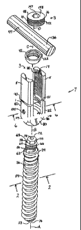
[0018] Fig. 1 is an exploded perspective view of a polyaxial
bone screw assembly according to the present invention having
12
CA 02623206 2010-05-14
a shank, a receiver with arm extensions, and a shank
retaining structure and further showing a rod and closure
structure.
[0019]
13
CA 02623206 2008-03-19
adjacent to the arms, the extensions having weakened
regions, the extensions bendable and removable from the
arms at the weakened regions; and the arms and the
extensions each having inwardly facing surfaces with
discontinuous helically wound reverse angle structure
thereon adapted to interlock radially with a mating
reverse angle structure on a closure and to allow
advancement and transfer of the closure between the
extensions and the arms by rotation of the closure.
[0017] Other objects and advantages of this invention
will become apparent from the following description taken
in conjunction with the accompanying drawings wherein are
set forth, by way of illustration and example, certain
embodiments of this invention.
[0018] The drawings constitute a part of this
specification and include exemplary embodiments of the
present invention and illustrate various objects and
features thereof.
Brief Description of the Drawings
[0019] Fig. 1 is an exploded perspective view of a
polyaxial bone screw assembly according to the present
invention having a shank, a receiver with arm extensions,
and a shank retaining structure and further showing a rod
and closure structure.
13
CA 02623206 2008-03-19
[0020] Fig. 2 is an enlarged cross-sectional view of
the shank taken along the line 2-2 of Fig. 1.
[0021] Fig. 3 is an enlarged top plan view of the
shank of Figs 1 and 2.
[0022] Fig. 4 is an enlarged top plan view of the
retaining structure of Fig. 1.
[0023] Fig. 5 is an enlarged cross-sectional view
taken along the line 5-5 of Fig. 4.
[0024] Fig. 6 is a cross-sectional view of the
receiver taken along the line 6-6 of Fig. 1 and showing
the retaining structure seated in the receiver, also in
cross-section, and illustrating the retaining structure
being inserted into the receiver in dashed lines.
[0025] Fig. 7 is an enlarged and fragmentary side
elevational view of the assembly of Fig. 1 with portions
broken away to show the detail thereof, illustrating the
retaining structure mated with the shank and the closure
structure pressing upon a rod disposed between the arm
extensions and reducing the rod toward the receiver by
rotation of a tool engaged with the closure structure.
[0026] Fig. 8 is an enlarged and fragmentary view
similar to Fig. 7 showing the rod engaged with both the
shank and the closure structure and with the arm
extensions removed.
[0027] Fig. 9 is a cross-sectional view taken along
the line 9-9 of Fig. 8.
14
CA 02623206 2008-03-19
[0028] Fig. 10 a fragmentary and enlarged perspective
view of the assembly of Fig. 1 shown completely assembled
with the rod and closure structure.
Detailed Description of the Invention
[0029] As required, detailed embodiments of the
present invention are disclosed herein; however, it is to
be understood that the disclosed embodiments are merely
exemplary of the invention, which may be embodied in
various forms. Therefore, specific structural and
functional details disclosed herein are not to be
interpreted as limiting, but merely as a basis for the
claims and as a representative basis for teaching one
skilled in the art to variously employ the present
invention in virtually any appropriately detailed
structure.
[0030] Referring to the drawings in more detail, the
reference numeral 1 designates a receiver according to
the invention having a component of a helical guide and
advancement reverse angle structure, generally 3, in
combination with upwardly extending break-off tabs or
extensions 5 used in conjunction with a medical implant
assembly, generally 7, that embodies the present
invention. It is noted that any reference to the words
top, bottom, up and down, and the like, in this
application refers to the alignment shown in the various
CA 02623206 2008-03-19
drawings, as well as the normal connotations applied to
such devices, and is not intended to restrict positioning
of the receiver 1 and the medical implant assembly 7 in
actual use.
[0031] The reverse angle guide and advancement
structure 3 according to the invention includes a reverse
angle thread form 10 extending helically on an inner
member 16 and a complimentary reverse angle thread form
19 extending helically within an outer member 21
illustrated in the drawings as being a portion of the
receiver 1. The reverse angle thread forms 10 and 19
cooperate to helically guide the inner member 16 into the
outer member 21 when the inner member 16 is rotated and
advanced into the outer member 21. The inner and outer
thread forms 10 and 19 provide respective anti-splay
surfaces 24 and 26 that cooperate to prevent splaying
tendencies of the outer member 21 when the inner member
16 is strongly torqued therein.
[0032] In the illustrated embodiment the medical
implant assembly 7 includes the bone screw receiver 1
embodying the outer member 21, and further includes a
shank 34 having a body 36 integral with an upper portion
or capture structure 38 and a retaining structure 42.
The shank 34, the receiver 1 and the retaining structure
42 preferably are assembled prior to implantation of the
shank body 36 into a vertebra 45.
16
CA 02623206 2008-03-19
[0033] Fig. 1 further shows the illustrated inner
member 16 as part of a closure structure 48 that is
helically advanced by rotation thereof into the receiver
1 and torqued against a longitudinal member, such as a
rod 49, to clamp the rod 49 within the receiver 1.
Although embodiments of the outer member 21 and the inner
member 16 are illustrated herein as the receiver 1 and
the closure 48, the reverse angle structure 3 is not
intended to be limited to such an application. It is
especially noted that the implant assembly 7 may be a
hook or other implant structure having a receiving
channel for a rod or other structural member. Also,
while the illustrated implant assembly 7 is shown as a
polyaxial assembly, it is intended that the reverse angle
structure 3 be adaptable for use with other types of
polyaxial assemblies as well as mono-axial bone screws,
hooks, and other types of implants.
[0034] As will be described in greater detail below,
the closure structure 48 biases the rod 49 or other
longitudinal member against the upper portion or capture
structure 38 of the shank 34 that in turn biases the
retaining structure 42 into fixed frictional contact with
the receiver 1, so as to fix the rod 49 relative to the
vertebra 45. The receiver 1 and the shank 34 cooperate
in such a manner that the receiver 1 and the shank 34 can
be secured at any of a plurality of angles, articulations
or rotational alignments relative to one another and
17
CA 02623206 2008-03-19
within a selected range of angles both from side to side
and from front to rear, to enable flexible or articulated
engagement of the receiver 1 with the shank 34 until both
are locked or fixed relative to each other near the end
of an implantation procedure.
[0035] The shank 34, best illustrated in Figs. 1-3, is
elongate, with the shank body 36 having a helically wound
bone implantable thread 54 extending from near a neck 56
located adjacent to the capture structure 38 to a tip 58
of the body 36 and extending radially outwardly
therefrom. During use, the body 36 utilizing the thread
54 for gripping and advancement is implanted into the
vertebra 45 leading with the tip 58 and driven down into
the vertebra 45 with an installation or driving tool (not
shown), so as to be implanted in the vertebra 45 to near
the neck 56, as shown in Figs. 8-10, and as is described
more fully in the paragraphs below. The shank 34 has an
elongate axis of rotation generally identified by the
reference letter A.
[0036] The neck 56 extends axially outward and upward
from the shank body 36. The neck 56 is of reduced radius
as compared to an adjacent top 62 of the body 36.
Further extending axially and outwardly from the neck 56
is the capture structure 38 that provides a connective or
capture apparatus disposed at a distance from the body
top 62 and thus at a distance from the vertebra 45 when
the body 36 is implanted in the vertebra 45.
18
CA 02623206 2008-03-19
[0037] The capture structure 38 is configured for
connecting the shank 34 to the receiver 1 and capturing
the shank 34 in the receiver 1. The capture structure 38
has an outer substantially cylindrical surface 64 having
a helically wound advancement structure thereon which in
the illustrated embodiment is a V-shaped thread 66
extending from near the neck 56 to adjacent to a seating
surface 68. Although a simple thread 66 is shown in the
drawings, it is foreseen that other structures including
other types of threads, such as buttress and reverse
angle threads, and non threads, such as helically wound
flanges with interlocking surfaces, may be alternatively
used in alternative embodiments of the present invention.
[0038] The shank 34 further includes a tool engagement
structure 70 disposed near a top end surface or dome 72
thereof for engagement of a driving tool (not shown) that
includes a driving structure in the form of a socket.
The driving tool is configured to fit about the tool
engagement structure 70 so as to form a socket and mating
projection for both driving and rotating the shank body
36 into the vertebra 45. Specifically in the embodiment
shown in Figs. 1-10, the tool engagement structure 70 is
in the shape of a hexagonally shaped extension head
coaxial with both the threaded shank body 36 and the
threaded capture structure 38.
[0039] The top surface 72 of the shank 34 is
preferably curved or dome-shaped as shown in the
19
CA 02623206 2008-03-19
drawings, for positive engagement with the rod 49, when
the bone screw assembly 7 is assembled, as shown in Figs.
8-10 and in any alignment of the shank 34 relative to the
receiver 1. In certain embodiments, the surface 72 is
smooth. While not required in accordance with practice
of the invention, the surface 72 may be scored or knurled
to further increase frictional engagement between the
surface 72 and the rod 49.
[0040] The shank 34 shown in the drawings is
cannulated, having a small central bore 74 extending an
entire length of the shank 34 along the axis A. The bore
74 is defined by an inner cylindrical wall 75 of the
shank 4 and has a first circular opening 76 at the shank
tip 58 and a second circular opening 78 at the top
surface 72. The bore 74 is coaxial with the threaded
body 36 and the capture structure outer surface 64. The
bore 74 provides a passage through the shank 34 interior
for a length of wire (not shown) inserted into the
vertebra 45 prior to the insertion of the shank body 36,
the wire providing a guide for insertion of the shank
body 36 into the vertebra 45.
[0041] Referring to Figs. 1 and 6 through 10, the
receiver 1 has a generally U-shaped appearance with a
partially cylindrical inner profile and a faceted outer
profile. The receiver 1 includes a somewhat spherical
base 80 integral with a pair of upstanding arms 82
forming a U-shaped cradle and defining a U-shaped channel
CA 02623206 2008-03-19
84 between the arms 82 with a lower seat 86 having
substantially the same radius as the rod 49 for operably
snugly receiving the rod 49.
[0042] Referring particularly to Figs. 1, 6 and 7, the
receiver 1 is provided with the break-off extensions or
arm tabs 5 to increase the initial length of the arms 82
and, thus, forming a rod receiving passageway between the
extensions 5 and thereby increasing the length of the rod
receiving channel 84 by the length of the passageway.
The purpose for the lengthened channel 84 is to enable
capture of the rod 49 within the channel 84 at a greater
distance from the vertebra 45, whereby the rod 49 can be
captured by the closure structure 48 and be "reduced" or
urged toward a seated position within the channel 84 by
advancement of the closure 48. This provides effective
leverage in reducing the position of the rod 49 or the
vertebra itself. For this purpose, inner surfaces 88 of
the extensions or tabs 5 are provided with the reverse
angle thread 19 that extends continuously from main
portions of the arms 82 and along the extensions 5 to
form a continuous and uniform helical pathway
therebetween.
[0043] A pair of weakened regions 90 is disposed
between the arm main portions 82 and the break-off
extensions 5. The weakened regions 90 may be regions
adjacent v-shaped indentations or notches extending
generally perpendicular to the axis A as illustrated in
21
CA 02623206 2008-03-19
Figs. 1, 6 and 7, or any other type of diminishing or
lessening in the arm thickness to provide for ready
separation of the extension 5 from the arms 82 by
breaking the extensions 5 off of the arms 82 at the
weakened regions 90. The weakened regions 90 are strong
enough to enable the rod 49 to be urged toward its seated
position (Figs. 8 and 9). However, the extensions 5 can
be broken off or separated from the main portions of the
arms 82 by pivoting or bending the extensions 5 back and
forth about the regions 90 while the main portions of the
arms are held in place, after the closure structure 48
has passed between the extensions 5. The resulting low-
profile implanted structure is shown in Figs. 8-10.
[0044] The reverse angle thread form 19 is disposed
about the inner surface 88 of the extensions 5 and the
arms 82 in a discontinuous generally helical pattern or
configuration, which is typical of threads and can have
various pitches, be counterclockwise advanced or vary in
most of the ways that conventional threads vary. The
thread form 19 has a leading surface 92 and a trailing
surface 94 that has also been identified previously
herein as the anti-splay surface 26. As used herein the
terms leading and trailing refer to the direction of
advancement with respect to mating engagement with the
closure structure 48 when used to close the receiver 1 by
moving the closure structure in a direction along a
central axis of rotation B of the receiver 1 toward the
22
CA 02623206 2008-03-19
base 80 of the receiver 1. In the illustrated
embodiment, advancement is produced by clockwise rotation
of the closure structure 48. As can be seen in Figs. 6
and 7, the general shape of the cross section of the
thread 19 is that of an obtuse triangle. It can also be
seen that the intersection of the leading surface 92 and
the trailing surface 94 with a plane passing through the
axis of rotation B, shows that both surfaces 92 and 94
slope downwardly in a direction toward the base 80 of the
receiver 1 from a root 96 to a crest 98 of the thread
form 19. As compared to a buttress thread wherein the
trailing surface is disposed perpendicular to the axis of
rotation, in a reverse angle thread form of the
invention, the trailing surface is disposed at an angle
with respect to the axis of rotation, the surface sloping
in generally the same direction as the leading surface.
This also contrasts with convention V-threads wherein the
leading and trailing surfaces slope in opposed
directions. The intersection of the trailing surface 94
with a plane passing through the axis of rotation B is
typically at an angle of from about to to about 450
relative to a line perpendicular to the axis of rotation
B. Further details regarding reverse angle threads of
the invention are described in U.S. Patent Application
Serial No. 09/644,777, filed August 23, 2000,
incorporated by reference herein.
23
CA 02623206 2008-03-19
[0045] Tool engaging apertures 104 are formed on outer
surfaces or facets of the arms 82. The apertures 104 may
be used for holding the receiver 1 during assembly with
the shank 34 and the retaining structure 42 and also
during the implantation of the shank body 36 into the
vertebra 45. Communicating with the apertures 104 are
upwardly projecting, hidden inner recesses 106. A
holding tool (not shown) is sized and shaped to have
structure to mate with and to be received in the aperture
104 and locked into place by pulling the holding tool
slightly axially upward relative to the base 80 and
toward the arm extensions 5. The holding tool and
respective apertures 104 may be configured for a variety
of engagement orientations, including, but not limited
to, a twist on/twist off or a snap on/snap off engagement
wherein the holding tool has legs that splay outwardly to
position the tool for engagement in the apertures 104 and
recesses 106. It is noted that the apertures 104 and
the cooperating holding tool may be configured to be of a
variety of sizes and locations along any of the surfaces
of the arms 82.
[0046] Communicating with and located beneath the U-
shaped channel 84 of the receiver 1 is a chamber or
cavity 108 substantially defined by an inner surface 110
of the base 80, the cavity 108 opens upwardly into the U-
shaped channel 84. The inner surface 110 is
substantially spherical, with at least a portion thereof
24
CA 02623206 2008-03-19
forming a partial internal spherical seating surface 112.
The surface 112 is sized and shaped for mating with the
retaining structure 42, as described more fully below.
[0047] The base 80 further includes a restrictive neck
113, having a radius smaller than a radius of the
spherical surface 110. The neck 113 defines a bore 114
communicating with the cavity 108 and a lower exterior
116 of the base 80. The bore 114 is coaxially aligned
with respect to the rotational axis B of the receiver 1.
The neck 113 and associated bore 114 are sized and shaped
to be smaller than a radial dimension of the retaining
structure 42, as will be discussed further below, so as
to form a restriction at the location of the neck 113
relative to the retaining structure 42, to prevent the
retaining structure 42 from passing from the cavity 108
and out into the lower exterior 116 of the receiver 1
when the retaining structure 42 is seated within the
receiver 1. However, it is foreseen that the retaining
structure could be compressible (such as where such
structure has a missing section) and that the retaining
structure could be loaded through the neck 113 and then
allowed to expand and fully seat in the spherical seating
surface of the receiver 1.
[0048] The retaining structure or ring 42 is used to
retain the upper portion or capture structure 38 of the
shank 34 within the receiver 1. The retaining structure
CA 02623206 2008-03-19
42, best illustrated by Figs. 4-5, has an operational
central axis that is the same as the elongate axis A
associated with the shank 34, but when the retaining
structure 42 is separated from the shank 34, the axis of
rotation is identified as axis C, as shown in Fig. 5.
The retaining structure 42 has a central bore 120 that
passes entirely through the retaining structure 42 from a
top surface 122 to a bottom surface 124 thereof. A first
inner cylindrical surface 126 defines a substantial
portion of the bore 120, the surface 126 having a
helically wound guide and advancement structure thereon
as shown by a helical rib or thread 128 extending from
adjacent the bottom surface 124 to adjacent a flat,
seating surface 129 disposed perpendicular to the inner
surface 126.
[0049] Although a simple helical rib 128 is shown in
the drawings, it is foreseen that other helical
structures including other types of threads, such as
buttress and reverse angle threads, and non threads, such
as helically wound flanges with interlocking surfaces,
may be alternatively used in an alternative embodiment of
the present invention. The inner cylindrical surface 126
with helical rib 128 are configured to mate under
rotation with the capture structure outer surface 64 and
helical guide and advancement structure or thread 66, as
described more fully below.
26
CA 02623206 2008-03-19
[0050] The retaining structure 42 further includes a
second inner wall or cylindrical surface 132, coaxial
with the first inner cylindrical surface 126. The
surface 132 is disposed between the seating surface 129
and the top surface 122 of the retaining structure 42 and
has a diameter greater than that of the cylindrical
surface 126. As will be described more fully below, the
cylindrical surface 132 in cooperation with the seating
surface 129 and the surface 68 of the capture structure
38, provide a recess about the base of the tool
engagement structure 70 and a stable seating surface for
the tool (not shown) used to drive the shank body 36 into
bone. The surface or wall 132 which is the outer wall of
the recess may be shaped to fit an outer surface of such
a driving tool and may be faceted, for example, hexagonal
in shape, to better grip the driving tool.
[0051] The retaining structure or ring 12 has a
radially outer partially spherically shaped surface 134
sized and shaped to mate with the partial spherically
shaped seating surface 112 of the receiver 1 and having a
radius approximately equal to the radius associated with
the surface 112. The retaining structure radius is
larger than the radius of the neck 113 of the receiver 1.
Although not required, it is foreseen that the outer
partially spherically shaped surface 134 may be a high
friction surface such as a knurled surface or the like.
27
CA 02623206 2008-03-19
[0052] The elongate rod or longitudinal member 49 that
is utilized with the assembly 7 can be any of a variety
of implants utilized in reconstructive spinal surgery,
but is normally a cylindrical elongate structure having a
cylindrical surface 136 of uniform diameter and having a
generally smooth surface. The rod 49 is preferably sized
and shaped to snugly seat near the bottom of the U-shaped
channel 84 of the receiver 1 and, during normal
operation, is positioned slightly above the bottom of the
channel 84 at the lower seat 86. In particular, the rod
49 normally directly or abutingly engages the shank top
surface 72, as shown in Figs. 8 and 9 and is biased
against the dome shank top surface 72, consequently
biasing the shank 34 downwardly in a direction toward the
base 80 of the receiver 1 when the assembly 7 is fully
assembled. For this to occur, the shank top surface 72
must extend at least slightly into the space of the
channel 84 when the retaining structure 42 is snugly
seated in the lower part of the receiver cavity 108. The
shank 34 and the retaining structure 42 are thereby
locked or held in position relative to the receiver 1 by
the rod 49 firmly pushing downward on the shank top
surface 72.
[0053] With reference to Figs. 1 and 6-10, the closure
structure or closure top 48 can be any of a variety of
different types of closure structures for use in
conjunction with the mating structure on the main
28
CA 02623206 2008-03-19
portions of the upstanding arms 82 and the arm break-off
extensions 5. The illustrated closure top 48 is a
cylindrically shaped plug having a generally cylindrical
shaped radially outer surface 142, a flat top 143 and a
substantially flat bottom 144. The closure structure 48
has an axis of rotation, generally indicated by the
reference numeral D. The axis of rotation D is at the
radial center of the closure structure 48. An internal
tool engagement structure in the form of an aperture or
bore 147 that is co-axial with the axis of rotation D
extends through the top 143 and partially through the
closure structure 48. The aperture 147 is poly-faceted
so as to have a hexagonal cross section such that the
closure structure 48 can be installed or removed with an
allen type tool 148 that is engageable with the structure
48 at the aperture 147. Although a hex-shaped aperture
147 is shown in the drawings, the tool engagement
structure may take a variety of tool-engaging forms, such
as multi-lobular drives sold under the trademark TORX, or
may include more than one aperture of various shapes,
such as a pair of spaced apertures, or the like.
Although a particular closure structure 48 has been
illustrated herein, it is foreseen that the invention can
be used in conjunction with plugs and set screws of
various types and configurations. For example, the
closure structure may include a break off head for
insertion.
29
CA 02623206 2008-03-19
[0054] The closure structure 48 also includes
structure to assist in engaging and securing the rod 49,
shown as a point 149 for penetrating the rod surface 136.
Although not shown, such a closure structure may further
include a cutting rim and/or a roughened under surface.
[0055] The closure structure 48 outer substantially
cylindrical surface 142 embodies the inner member 16
having the reverse angle thread form 10. The thread form
includes a leading surface 152 and a trailing surface
154 that has also been identified herein as the anti-
splay surface 24. As with the description herein with
respect to the receiver 1, the terms leading and trailing
refer to the direction of advancement of the closure
structure 48 into the receiver 1 by moving the closure
structure 48 in a direction along the central axis of
rotation B of the receiver 1 (also about the axis D of
the structure 48) and toward the base 80 of the receiver
1. The general shape of the cross section of the thread
10 is that of an obtuse triangle. It can be seen that at
the intersection of the leading surface 152 and the
trailing surface 154 with a plane passing through the
axis of rotation D, both surfaces 152 and 154 slope
upwardly or rearwardly in a direction away from the
bottom surface 144 of the closure 48 from a root 156 to a
crest 158 of the thread form 10. Both surfaces 152 and
154 also slope upwardly or rearwardly in a direction away
CA 02623206 2008-03-19
from the base 80 of the receiver 1 when the closure 48 is
engaged with the receiver 1.
[0056] The reverse angle thread form is shaped and
positioned so as to engage the discontinuous reverse
angle thread form 19 that winds on the extensions 5 and
the arms 82 to provide for rotating advancement of the
closure structure 48 into the receiver 1 when rotated
clockwise and, in particular, to cover the top or
upwardly open portion of the U-shaped channel 84 to
capture the rod 49, without splaying of the extensions 5
or the arms 82. The closure structure 48 also operably
biases against the rod 49 by advancement and applies
pressure to the rod 49 under torquing, so that the rod 49
is urged downwardly against the shank top end surface 72
that extends into the channel 84. Downward biasing of
the shank top surface 72 operably produces a frictional
engagement between the rod 49 and the surface 72 and also
urges the retaining structure 42 toward the base 80 of
the receiver 1, so as to frictionally seat the retaining
structure external spherical surface 134 fixedly against
the partial internal spherical seating surface 112 of the
receiver 1, also fixing the shank 34 and retaining
structure 42 in a selected, rigid position relative to
the receiver 1.
[0057] It is noted that as torque is applied to the
closure 48 in a clockwise manner so as to advance the
closure 48 in the receiver 1 the trailing surface 154
31
CA 02623206 2008-03-19
engages and pushes against the trailing surface 94 of the
thread 19 of the receiver 1. The force exerted on the
closure 48 by this process is countered by a reactive
force acting on the receiver 1 that has a first component
that is axial, that is parallel to the axis of rotation D
of the closure structure 48, and a second component that
has a radial inward vector, that is toward the axis of
rotation D of the closure structure 48.
[0058] Prior to the polyaxial bone screw assembly 7
being placed in use according to the invention, the
retaining structure 42 is typically first inserted or
top-loaded, into the receiver U-shaped channel 84, as is
shown in dotted lines in Fig. 6, and then into the cavity
108 to dispose the structure 42 within the inner surface
110 of the receiver 1. Then, the retaining structure 42
is rotated approximately 90 degrees so as to be coaxial
with the receiver 1 and then seated in sliding engagement
with the seating surface 112 of the receiver 1, also
shown in Fig. 6.
[0059] With reference to Fig. 7, the shank capture
structure 38 is pre-loaded, inserted or bottom-loaded
into the receiver 1 through the bore 114 defined by the
neck 113. The retaining structure 42, now disposed in
the receiver 1 is coaxially aligned with the shank
capture structure 38 so that the helical guide and
advancement structure 66 rotatingly mates with the
32
CA 02623206 2008-03-19
helical guide and advancement structure 128 of the
retaining structure 42.
[0060] The shank 34 and or the retaining structure 42
are rotated to fully mate the structures 66 and 128 along
the respective cylindrical surfaces 64 and 126, fixing
the capture structure 38 to the retaining structure 42,
until the seating surface 68 and the seating surface 129
are contiguous and disposed in the same plane as shown in
Figs. 7-9. Permanent, rigid engagement of the capture
structure 38 to the retaining structure 42 may be further
ensured and supported by the use of adhesive, a spot
weld, deforming one or both threads with a punch or the
like. At this time the shank 34 is in slidable and
rotatable engagement with the receiver 1, while the
capture structure 38 and the lower aperture or neck 113
of the receiver 1 cooperate to maintain the shank body 36
in rotational relation with the receiver 1. Only the
retaining structure 42 is in slidable engagement with the
head spherical seating surface 112. Both the capture
structure 38 and threaded portion of the shank body 36
are in spaced relation with the receiver 1.
[0061] The assembly 7 is then typically screwed into a
bone, such as the vertebra 45, by rotation of the shank
34 using a driving tool (not shown) that operably drives
and rotates the shank 34 by engagement thereof with the
hexagonally shaped extension head 70 of the shank 34.
Preferably, when the driving tool engages the tool
33
CA 02623206 2008-03-19
engagement structure or head 70, an end portion thereof
is disposed in a recess defined by the structure 70, the
seating surface 68, the contiguous seating surface 129
and the inner cylindrical surface 132, with a bottom
surface of the driving tool contacting and frictionally
engaging both the seating surface 68 and the seating
surface 129. Some frictional engagement between an outer
surface of the driving tool with the cylindrical surface
132 may also be achievable during rotation of the driving
tool.
[0062] Typically, the receiver 1 and the retaining
structure 42 are assembled on the shank 34 before
inserting the shank body 36 into the vertebra 45, but in
certain circumstances, the shank body 36 can be first
partially implanted with the capture structure 38
extending proud to allow assembly with the receiver 1
utilizing the retaining structure 42. Then the shank
body 36 can be further driven into the vertebra 45.
[0063] The vertebra 45 may be pre-drilled to minimize
stressing the bone and have a guide wire (not shown) that
is shaped for the cannula 74 inserted to provide a guide
for the placement and angle of the shank 34 with respect
to the vertebra 45. A further tap hole may be made
using a tap with the guide wire as a guide. Then, the
assembly 7 or the solitary shank 34, is threaded onto the
guide wire utilizing the cannulation bore 74 by first
threading the wire into the bottom opening 76 and then
34
CA 02623206 2008-03-19
out of the top opening 78. The shank 34 is then driven
into the vertebra 45, using the wire as a placement
guide.
[0064] With reference to Figs. 7-10, the rod 49 is
eventually positioned between the break-off extensions 5
and the closure structure 48 is then inserted into and
advanced between the extensions 5 by mating the thread 10
with the thread 19, and rotating the structure 48
downwardly toward the base 80 so as to bias or push
against the rod 49. Pressure applied to the rod 49 by the
structure 48 is continued as the rod 40 passes from the
extensions 5 to a position disposed between the receiver
arms 82 and near the seat 86. The anti-splay reverse
angle structure 3 of the cooperating closure structure
48, the break-off extensions 5 and the arms 82, bias the
extensions 5 and arms 82 toward one another as the
closure structure 48 travels downwardly toward the base
80 of the receiver 1. Once both the rod and the closure
structure 48 are disposed in the receiver 1 between the
arms 82, the break-off extensions 5 may be removed by
bending the extensions 5, causing the extensions 5 to
break away from the arms 82 at the weakened regions 90.
The closure structure 48 may then be further tightened
against the rod 49 as desired.
[0065] The shank top end surface 72, because it is
rounded to approximately equally extend upward into the
channel 84 approximately the same amount no matter what
CA 02623206 2008-03-19
degree of rotation exists between the shank 34 and the
receiver 1 and because the domed surface 72 is sized and
shaped to extend upwardly into the U-shaped channel 84,
the surface 72 is engaged by the rod 49 and pushed
downwardly toward the base 80 of the receiver 1 when the
closure structure 48 biases downwardly toward and onto
the rod 49. The downward pressure on the shank 34 in
turn urges the retaining structure 42 downward toward the
receiver seating surface 112, with the retaining
structure seating surface 129 in frictional engagement
with the receiver seating surface 112. As the closure
structure 48 presses against the rod 49, the rod 49
presses against the shank and the retaining structure 42
that is now rigidly attached to the shank 34 which in
turn becomes frictionally and rigidly attached to the
receiver 1, fixing the shank body 36 in a desired angular
configuration with respect to the receiver 1 and the rod
49.
[0066] Fig. 10 illustrates the polyaxial bone screw
assembly 7 and including the rod 49 and the closure
structure 48 positioned in a vertebra 45. The axis A of
the bone shank 34 is illustrated as not being coaxial
with the axis B of the receiver 1 and the shank 34 is
fixed in this angular locked configuration. Other
angular configurations can be achieved, as required
during installation surgery due to positioning of the rod
49 or the like.
36
CA 02623206 2008-03-19
[0067] If removal of the assembly 7 and associated rod
49 and closure structure 48 is necessary, disassembly is
accomplished by using the driving tool 148 or other
similarly sized tool of an Allen wrench type (not shown)
mating with the aperture 147 and turned counterclockwise
to rotate the closure structure 48 and reverse the
advancement thereof in the receiver 1. Then, disassembly
of the assembly 7 is accomplished in reverse order to the
procedure described previously herein for assembly.
[0068] It is to be understood that while certain forms
of the present invention have been illustrated and
described herein, it is not to be limited to the specific
forms or arrangement of parts described and shown.
37