Note: Descriptions are shown in the official language in which they were submitted.
CA 02633280 2008-06-13
WO 2007/078749 PCT/US2006/047447
1
APPARATUS, SYSTEM, AND METHOD FOR
PRINT QUALITY MEASUREMENTS
TECHNICAL FIELD
[0001] This disclosure relates generally to printing
systems and more specifically to an apparatus, system, and
method for print quality measurements.
CA 02633280 2008-06-13
WO 2007/078749 PCT/US2006/047447
2
BACKGROUND=
[0002] Different types of printing systems are available
and used to print newspapers, books, and other documents.
These conventional printing systems often include
s components such as in-line presses, common-impression-
cylinder presses, and blanket-to-blanket presses. Some
conventional printing systems are used to produce printing
on large streams of paper, such as paper that is three
meters wide. Some conventional printing systems are also
used to produce printing on quickly moving paper, such as
paper that is moving at twenty meters per second. Some
conventional printing systems also incorporate multiple
printing steps, such as systems that support the sequential
application of inks of different colors or appearance,
i.s laquers or other surface sealants, and so forth.
[0003] It is often necessary to monitor the quality of
the printing provided by a conventional printing system.
As an example, it is often desirable to monitor the quality
of the printing on newspapers to ensure that the
conventional printing system is operating properly. This
may also allow problems with the conventional printing
system to be detected and resolved. However, conventional
print quality monitoring techniques typically suffer from
various problems. For example, conventional print quality
monitoring techniques are often slow and expensive. Also,
there is often a small or limited amount of space in which
a print quality monitoring instrument can be installed and
used. This typically limits the functionality that can be
provided by the instrument.
CA 02633280 2008-06-13
WO 2007/078749 PCT/US2006/047447
3
SUMMARY
[0004] This disclosure provides an apparatus, system,
and method for print quality measurements.
[0005] In a first embodiment, an apparatus includes at
least one scanner. Each scanner includes a plurality of
sensors, and each sensor is capable of measuring one or
more characteristics associated with a portion of a
substrate. The substrate has printing produced by a
printing system. The apparatus also includes a controller
capable of receiving at least some of the measurements from
the plurality of sensors and determining a quality of the
printing on the substrate using the received measurements.
[0006] In particular embodiments, the substrate
represents paper, and the printing system represents an
is offset printing system.
[0007] In other particular embodiments, at least one of
the sensors is in a fixed position and/or at least one of
the sensors is movable over part of a surface of the
substrate.
[0008] In yet other particular embodiments, the
determined quality of the printing involves one or more of
density, dot area, dot gain, contour sharpness, doubling,
mottling, ghosting, slur, improper positioning of the
printing, and misregister of different colored inks.
[0009] in a second embodiment, a system includes a
printing system capable of producing printing on a
substrate. The system also includes a print quality
monitor having at least one scanner. Each scanner includes
a plurality of sensors, and each sensor is capable of
measuring one or more characteristics associated with a
portion of the substrate. In addition, the system includes
a controller capable of receiving at least some of the
CA 02633280 2008-06-13
WO 2007/078749 PCT/US2006/047447
4
measurements from the plurality of sensors and determining
a quality of the printing on the substrate using the
received measurements.
[0010] In a third embodiment, a method; includes
measuring one or more characteristics associated with a
portion of a substrate using at least one scanrier. Each
scanner has a plurality of sensors, and the substrate-has
printing produced by a printing system. The method also
includes determining a quality of the printing on the
substrate using at least some of the measurements from the
plurality of sensors.
[0011] Other technical features may be readily apparent
to one skilled in the art from the following figures,
descriptions, and claims.
CA 02633280 2008-06-13
WO 2007/078749 PCT/US2006/047447
BRIEF DESCRIPTION OF THE DRAWINGS
[0012] For a more complete understanding of this
disclosure, reference is now made to the following
description, taken in conjunction with the accompanying
5 drawings, in which:
[0013] FIGURE 1 illustrates an example system for print
quality measurements according to one embodiment of this
disclosure;
[0014] FIGURES 2A through 2E illustrate details of
example scanners in a system for print quality measurements
according to one embodiment of this disclosure;
[0015] FIGURES 3A through 3C illustrate example
configurations of print quality monitors in a system for
print quality measurements according to one embodiment of
l.s this =disclosure; and
[0016] FIGURE 4 illustrates an example method for print
quality measurements according to one embodiment of this
disclosure.
CA 02633280 2008-06-13
WO 2007/078749 PCT/US2006/047447
6
DETAILED DESCRIPTION
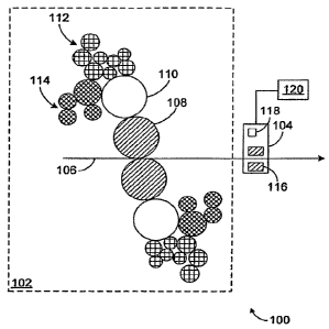
[0017] FIGUR.E 1 illustrates an example system 100 for
print quality measurements according to one embodiment of
this disclosure. The embodiment of the system 100 shown in
FIGURE 1 is for illustration only. Other embodiments of
the system 100 could be used without departing from the
scope of this disclosure.
[0018] In this example, the system 100 includes a
printing press 102 and a print quality monitor. 104. The
printing press 102 is capable of printing content (such as
text and images) on a substrate 106 (such as paper). In
particular embodiments, the substrate 106 could represent
paper or other material that is approximately three meters
wide and that moves through the printing press 102 at up to
twenty meters per second or more.
[00191 In this particular example, the printing press
102 represents a blanket-to-blanket press that includes two
blanket cylinders 108, two plate cylinders 110, two inking
units 112, and two dampening units 114. The blanket
cylinders 108 are capable of creating the actual printing
on the substrate 106. For example, a rubber blanket or
other type of blanket may be mounted on each blanket
cylinder 108, and ink may be transferred onto the blanket
and then onto the substrate 106. The plate cylinders 110
may include printing plates, which receive ink and then
transfer the ink onto the blankets mounted on the blanket
cylinders 108. In this way, the plate cyl.inders 110
control what is actually printed on the substrate 106. The
inking units 112 are responsible for transferring the ink
onto the plate cylinders 110. The dampening units 114 are
capable of using dampening fluid to dampen the plate
cylinders 110, which helps to facilitate the transfer of
CA 02633280 2008-06-13
WO 2007/078749 PCT/US2006/047447
7
ink onto the blankets mounted on the blanket cylinders 108.
[0020] This represents a brief description of one type
of printing press 102 that may be used in the system 100.
Additional details regarding this type of printing press
102 are well-known in the art and are not needed for an
understanding of this disclosure. Also, this represents
one specific type of printing press 102 that may be used in
the system 100. The system 100 could include any other or
additional types of printing presses. For example, the
system 100 could include other offset printing or
lithography systems (including sheet-fed offset printing
presses), Gravure printing systems, letterpresses, and
screen printing systems. In addition, the printing press
102 could be capable of printing content on any suitable
substrate 106, such as paper, plastic, textiles, metal foil
or sheets, or other or additional substrates.
[0021] The print quality monitor 104 is capable of
scanning the substrate 106 after the printing press 102 has
created the printing on the substrate 106. The print
quality monitor 104 measures various characteristics about
the substrate 106 itself and/or the printing on the
substrate 106. In this way, the print quality monitor 104
can determine the quality of the printing produced by the
printing press 102. This may allow the print quality
monitor 104 to ensure that the printing press 102 is
operating properly and to identify potential problems with
the printing press 102.
[0022] In this example, the print quality monitor 104
includes one or more scanners 116. Each scanner 116
includes multiple sensors that are capable of scanning the
substrate 106 and taking measurements used to determine the
quality of the printing provided by the printing press 102.
Also, each sensor in the scanners 116 may be responsible
CA 02633280 2008-06-13
WO 2007/078749 PCT/US2006/047447
8
for scanning only a portion of the substrate 106 rather
than the entire width of the substrate 106. Each scanner
116 includes any suitable structure or structures for
measuring one or more characteristics about the substrate
106 itself and/or the printing on the substrate 106. As
particular examples, each scanner 116 could represent a
mini-scanner having one or more cameras, microscopes,
densitometers, colorimetric sensors, or other or additional
types of sensors. Also, each sensor in a scanner 116 could
be fixed or movable. In other embodiments, an additional
scanner may be used to scan the substrate 106 prior to the
printing process so that its sensors measure the properties
of the unprinted substrate 106.
[0023] As shown in FIGURE 1, the print quality monitor
104 may also include a controller 118. The controller 118
could use the measurements from the scanners 116 to
determine the quality of the printing on the substrate 106.
For example, the controller 118 could use the measurements
to determine if the density (ability of material to absorb
light), dot area (percentage of area occupied by dots), and
dot gain (change in size of dot from plate cylinder 110 to
substrate 106) of the printing is within acceptable levels.
The controller 118 could also use the measurements to
determine if the printing is suffering from doubling (faint
image offset from primary image), mottling (spotty or
cloudy appearance of ink on substrate 106), ghosting (image
elements overlap onto subsequent image areas), ink
misregister (lateral and/or longitudinal misalignment
between inks applied at sequential presses), or slur (round
dots; appear as elliptical dots). In addition, the
controller 118 could use the measurements to ensure that
the printing is properly positioned on the substrate 106,
such as by using register marks on the substrate 106 that
CA 02633280 2008-06-13
WO 2007/078749 PCT/US2006/047447
9
are detected by the scanners 116. The controller 118 could
use the measurements to make any other or additional
determinations. In other embodiments, the controller 118
could collect the measurements from the=scanners 116 and
provide the measurements to an external controller 120,
which makes print quality determinations using the
measurements. In yet other embodiments, the measurements
from the scanners 116 could be provided directly to the
external controller 120 without the use of a controller
io 118. Each of the controllers 118, 120 includes any
suitable hardware, software, firmware, or combination
thereof for making print quality determinations using
measurements from one or more scanners 116.
[0024] Additional details regarding the scanners 116 are
shown in FIGURES 2A through 2E, which are described below.
Also, example configurations of the print quality monitor
104 with respect to the printing press 102 are shown in
FIGURES 3A through 3C, which are described below.
[0025] Although FIGURE 1 illustrates one example of a
system 100 for print quality measurements, various changes
may be made to FIGURE 1. For example, as noted above,
other or additional types of printing presses could be used
in the system 100. Also, while shown as including two
scanners 116, the print quality monitor 104 could include a
single scanner 116 or more than two scanners 116. In
addition, the system 100 could include any number of
pririting presses 102 and any numberiof print quality
monitors 104.
[0026] FIGURES 2A through 2E illustrate details of
example scanners in a system for print quality measurements
according to one embodiment of this disclosure. In
particular, FIGURES 2A through 2D illustrate example sensor
arrays for use in a scanner 116, and FIGURE 2E illustrates
CA 02633280 2008-06-13
WO 2007/078749 PCT/US2006/047447
a housing of a scanner 116. The embodiments of the sensor
arrays and housing shown in FIGURES 2A through 2E are for
illustration only. Other scanners having other sensor
arrays or housings may be used without departing from the
5 scope of this disclosure. Also, for ease of explanation,
the sensor arrays and housing shown in FIGURES 2A through
2E are described with respect to the system 100 of FIGURE
1. The sensor arrays and housing could be used in a
scanner in any other suitable system.
10 [0027] In FIGURE 2A, a sensor array 200 in a scanner 116
includes multiple sensors 202 mounted on a movable frame
204. Each of the sensors 202 measures one or more
characteristics of the substrate 106 or the printing on the
substrate 106. For example, the sensors 202 could measure
the density, dot area, or dot gain (physical or optical) of
the printing. The sensors 202 could also measure doubling,
mottling, ghosting, misregister of different colored inks,
and slur of the printing. Further, the sensors 202 could
identify register marks or control strips on the substrate
106 itself or the sharpness of contours in the printing.
In addition, the sensors 202 could be used to measure
characteristics of areas of known interest on the substrate
106 (such as areas known or expected to contain'company or
product logos or images of people's faces) . Each sensor
202 represents any suitable= structure or structures for
measuring one or more characteristics of the substrate 106
or the printing on the substrate 106. As examples, the
sensors 202 could include densitometers,
spectrophotometers, camera-based colorimeters, filter-based
colorimeters, and camera-based microscopes. In the
illustrated example, the sensors 202 are evenly spaced on
the frame 204, although the sensors 202 may have any other
suitable spacing.
CA 02633280 2008-06-13
WO 2007/078749 PCT/US2006/047447
11
[0028] The movable frame 204 is attached to a frame
carrier 206, which is capable of moving the frame 204 back
and forth across a surface of the substrate 106. For
example, the substrate 106 could be divided into multiple
zones 208, and the frame carrier 206 could move the frame
204 back and forth =so that each sensor 202 passes over
multiple zones 208. In particular embodiments, each zone
208 is 1.25 inches wide, and the frame carrier 206 moves
the frame 204 so that each sensor 202 passes over four
zones 208. The frame carrier 206 includes any suitable
structure or structures for moving the frame 204 over the
substrate 106.. The frame carrier 206 could, for example,
represent a structure or structures for moving the frame
204 in a direction perpendicular to the direction of
is movement for the substrate 106.
[0029] FIGURE 2B illustrates another sensor array 220,
which uses a different movement mechanism than that shown
in FIGURE 2A. In this example, the sensor array 220
includes multiple sensors 222 that are slidably mounted on
a fixed frame 224. The sensors 222 are attached to a guide
226, such as a belt or a wire. The sensors 222 may be
attached to the guide 226 in any suitable manner, such as
by using sledges 228. Movement of the guide 226 is
controlled by a guide mover 230. The guide mover 230 is
capable of causing the guide 226 to rotate back and forth,
which causes each sensor 222 to move back and forth across
a surface of the substrate 106. By moving the sensors 222
with a guide 226 instead of moving the frame 224, the frame
224 in FIGURE 2B could be shorter than the frame 204 in
FIGURE 2A.
[0030] In FIGURE 2C, a sensor array 240 includes a
combination of fixably mounted sensors 242 and slidably
mounted sensors 244 on a fixed frame 246. In this example,
CA 02633280 2008-06-13
WO 2007/078749 PCT/US2006/047447
12
only the movable sensors 244 are attached to a guide 248 by
sledges 250. As a result, only the movable sensors 244
move back and forth across a surface of the substrate 106
under the control of a guide mover 252. The fixed sensors
242 remain in place over the substrate 106.
[0031] In FIGURE 2D, a sensor array 260 includes sensors
262-264 mounted on a frame 266 at an uneven or unequal
spacing. In this example, the sensors 262-264 could
represent different types of sensors. As a particular
example, the sensors 262 could represent camera-based
densitometers or other densitometers, and the sensors 264
could represent camera-based or other register and
microscope sensors. As shown in FIGURE 2D, the frame 266
may or may not be moved back and forth over the substrate
106 by a frame carrier 268. Movement of the sensors 262-
264 may not be needed, for example, if the sensors 262-264
are close enough to accurately monitor the quality of the
printing.
[0032] In some embodiments, the locations of the sensors
in the sensor arrays of FIGURES 2A through 2D can be
adjusted manually or automatically to achieve optimal
measurements for a particular print run. For example, to
verify that skin tone colors are correct, a colorimetric
sensor could be manually or automatically positioned so
that it is able to scan a printed image of a face on the
substrate 106.
[0033] FIGURE 2E illustrates a housing 280 for a scanner
116. In this example, the housing 280 includes a sensor
array 282, which may represent any of the sensor arrays
shown in FIGURES 2A through 2D, any other sensor array, or
any combination of sensor arrays. While shown as being
movable, the sensor array 282 could be fixed in the housing
280. Also, the sensor array 282 could have any suitable
CA 02633280 2008-06-13
WO 2007/078749 PCT/US2006/047447
13
size, and the size of the sensor array 282 may depend at
least partially on whether the sensor array 282 is fixed or
movable.
[0034] The housing 280 also includes one or more
calibration tiles 284. The calibration tiles 284 may
represent one or more tiles or other structures having one
or more known or standard colors. The calibration tiles
284 may be positioned so that one or more colorimetric
sensors in the sensor array 282 pass over the calibration
tiles 284 during a calibration of the scanner 116. In this
way, the sensors or other components may be calibrated to
ensure that proper measurements of the substrate 116 are
made during normal operation of the scanner 116. The
calibration tiles 284 may be positioned in the housing 280
i.5 so that they do not interfere with normal operation and
scanning of the substrate 106.
[0035] Although FIGURES 2A through 2E illustrate example
details of a scanner 116 in a system for print quality
measurements, various changes may be made to FIGURES 2A
through 2E. For example, FIGURES 2A through 2C illustrate
the use of a single type of sensor, while FIGURE 2D
illustrates the use of multiple types of sensors. Each
sensor array shown in FIGURES 2A through 2D could include
one or multiple types of sensors. Also, the number and
spacing of the sensors in FIGURES 2A through 2D are for
illustration only. Each sensor array could include any
suitable number of sensors having any suitable spacing.
The number of sensors could, for example, depend on the
maximum width of the substrate 106 and the desired spacing
between the sensors. in addition, the sensor arrays of
FIGURES 2A through 2D could be used with any other suitable
housing, and the housing of FIGURE 2E could be used with
any other suitable sensor arrays.
CA 02633280 2008-06-13
WO 2007/078749 PCT/US2006/047447
14
[0036] FIGURES 3A through 3C illustrate example
configurations of print quality monitors 104 in a system
for print quality measurements according to one embodiment'
of this disclosure. The configurations of the print
s quality monitors 104 shown in FIGURES 3A through 3C are for
illustration only. Other configurations may be used
without departing from the scope of this disclosure. Also,
for ease of explanation, the configurations' shown in
FIGURES 3A through 3C are described with respect to the
system 100 of FIGURE 1. The configurations could be used
in any other suitable system.
[0037] FIGURE 3A illustrates the use of a one-sided
print quality monitor 104 in a position where a substrate
106 is supported by a cylinder 302. Because the substrate
106 is supported by the cylinder 302, this may simplify the
scanning of the substrate 106 and the measuring of print
quality on the substrate 106. This is because the
substrate 106 typically cannot move closer to and farther
away from the print quality monitor 104 during scanning.
While FIGURE 3A shows the substrate 106 as being supported
by a cylinder 302, the substrate 106 could be supported in
other ways. For instance, guide.bars or plates may be used
to constrain the position of the substrate 106 instead of
or in addition to the use of cylinders.
[0038] FIGURE 3B illustrates the use of a one-sided
print quality monitor 104 in a position where the substrate
106 is not supported by any cylinders 322-324. Rather, in
this example, the substrate 106 is scanned in a location
between the two cylinders 322-324. As a result, it is
possible that the substrate 106 may flutter or move during
the scanning of the substrate 106. Similarly, FIGURE 3C
illustrates the use of a two-sided print quality monitor
104 in a position where the substrate 106 is not supported
CA 02633280 2008-06-13
WO 2007/078749 PCT/US2006/047447
by any cylinders 342-346. In this example, the substrate
106 is scanned in a location between the cylinders 344-346.
Again, it is possible that the substrate 106 may move
during the scanning of the substrate 106. In these
5 embodiments, the print quality monitor 104 could include or
otherwise operate in conjunction with optics or other
mechanisms that allow the print quality monitor 104 to
accurately scan the fluttering substrate 106.
[0039] The print quality monitors 104 could be
10 positioned in any suitable location or locations and=scan
the substrate 106 after any suitable operation or
operations in the system 100. For example, a print quality
monitor 104 could scan the substrate 106 after inks (such
as yellow, magenta, cyan, and black inks) have been applied
is to the substrate 106. A print quality monitor 104 could
also scan the substrate 106 after drying of the ink or
after lacquering of the substrate 106. In some
embodiments, the use of a two-sided print quality monitor
104 as shown in FIGURE 3C may require that an open draw of
substrate 106 be located in the system 100.
[0040] Although FIGURES 3A through 3C illustrate
examples of configurations. of print quality monitors 104 in
a system for print quality measurements, various changes
may be made to FIGURES 3A through 3C. For example, a
system could use one, some, or all of the configurations
shown in FIGURES 3A through 3C.
[0041] FIGURE 4, illustrates an example method 400 for
print quality measurements according to one embodiment of
this disclosure. For ease of explanation, the method 400
is described with respect to the system 100 of FIGURE 1.
The method 400 could be used by any suitable device and in
any suitable system.
[0042] The system 100 calibrates a print quality monitor
CA 02633280 2008-06-13
WO 2007/078749 PCT/US2006/047447
16
104 at step 402. This may include, for example, the print
quality monitor 104 moving a sensor over a calibration tile
.284. This may also include the print quality monitor 104
using colorimetric measurements from the sensor to
calibrate the print quality monitor 104.
[0043] The system 100 places printing on a substrate 106
at step 404. This may include, for example, the printing
press 102 placing inks onto paper or another substrate 106.
The printing press 102 could print text, images, and any
other or additional content onto the substrate 106.
[0044] The system 100 scans multiple portions of the
printed substrate 106 with multiple sensors at step 406.
This may include, for example, the print quality monitor
104 scanning the substrate 106 with sensors mounted on a
movable or fixed-frame. This may also include the print
quality monitor 104 moving at least some of the sensors
back and forth over the substrate 106. As particular
examples, this may include the sensors in the print quality
monitor 104 measuring density, dot area, dot gain,
doubling, mottling, ghosting, ink misregister, or slur of
the printing. This may also include the sensors in the
print quality monitor 104 identifying register marks or
control strips on the substrate 106.
[0045] The system 100 collects the measurements from the
sensors at'step 408. This may include, for example, the
controller 118 or the external controller 120 receiving
data representing the various mEasuieraents made by the
sensors in the print quality monitor 104.
[0046] The system 100 determines the quality of the
printing on the substrate 106 using at least some of the
measurements from the sensors at step 410. ' This may
include, for example, the controller 118 or the external
controller 120 determining whether the density, dot area,
CA 02633280 2008-06-13
WO 2007/078749 PCT/US2006/047447
17
or dot gain of the printing is within acceptable limits.
This may also include the controller 118 or the external
~
controller 120 determining whether the printing is
suffering from doubling, mottling, ghosting, ink
misregister, or slur. This may further include the
controller 118 or the external controller 120 determining
whether the printing is occurring in the proper areas of
the substrate 106. In addition, this may include the
controller 118 or the external controller 120 determining
the sharpness of contours in the printing, the physical
size of pixels in the printing, and other properties of the
printed pixels.
[0047] Although FIGURE 4 illustrates one example of a
method 400 for print quality measurements, various changes
may be made to FIGURE 4. For example, while shown as a
series of steps, various steps in FIGURE 4 could occur in
parallel or in a different order. Also, in determining the
quality of the printing on the substrate 106, the method
100 could also use measurements of properties of the
unprinted substrate 106 made prior to printing or
properties of unprinted portions of the substrate 106 after
printing.
[0048] It may be advantageous to set forth definitions
of certain words and phrases used throughout this patent
document. The terms "include" and "comprise," as well as
derivatives thereof, mean inclusion without limitation.
The term "or" is inclusive, meaning and/or. The phrases
"associated with" and "associated therewith, ' as well as
derivatives thereof, may mean to include, be included
within, interconnect with, contain, be contained within,
connect to or with, couple to or with, be communicable
with, cooperate with, interleave, juxtapose, be proximate
to, be bound to or with, have, have a property of, or the
CA 02633280 2008-06-13
WO 2007/078749 PCT/US2006/047447
xs
like. The term "controller" means any device, system, or
part thereof that controls at least one operation. A
controller may be implemented in hardware, firmware,,
software, or some combination of at least two of the same.
The functionality associated with any particular controller
may be centralized or distributed, whether locally or
remotely.
[0049] While this disclosure has described certain
embodiments and generally associated methods, alterations
and permutations of these embodiments and methods will be
apparent to those skilled in the art. For example, there
are many advantageous combinations of this disclosure with
other systems. As particular examples, measurements of
print quality may be supplied to a print quality control
system, which can adjust parameters of the printing process
to achieve an acceptable level of print quality. The print
quality control system could, for instance, adjust ink
fountain keys, moistening devices, tensioning devices, or
lateral and rotational offsets of printing cylinders.
Accordingly, the above description of example embodiments
does not- define or constrain this disclosure. Other
changes, substitutions, and alterations are also possible
without departing from the spirit and scope of this
disclosure, as defined by the following claims.
_