Note: Descriptions are shown in the official language in which they were submitted.
CA 02633866 2008-06-10
WO 2007/079415 PCT/US2006/062733
1
Title: Embolus Blood Clot Filter Removal System and Method
Priority Data and Incorporation by Reference
[0001] This application claims benefit of priority to U.S. Provisional Patent
Application No. 60/754,598, filed December 30, 2005 which is incorporated by
reference in
its entirety. This invention is related to the subject matter shown and
described in the
following: (i) PCT International Application No. , filed December 29, 2006,
having Attorney Docket No. 14673-007W0, entitled "Removable Blood Clot Filter
with
Edge For Cutting Through the Endothelium" and claiming the benefit of priority
to U.S.
Provisional Patent Application No. 60/754,600, filed December 30, 2005; (ii)
PCT
International Application No. , filed December 29, 2006, having Attorney
Docket No. 14673-004W0, entitled "Embolus Blood Clot Filter with Post Delivery
Actuation," and claiming the benefit of priority to U.S. Provisional Patent
Application No.
60/754,633, filed December 30, 2005; (iii) PCT International Application No.
filed December 29, 2006, having Attorney Docket No. 14673-008W4, entitled
"Embolus
Blood Clot Filter Delivery System," and claiming the benefit of priority to
U.S. Provisional
Patent Application No. 60/754,636, filed December 30, 2005; (iv) PCT
Tnternational
Application No. , filed December 29, 2006, having Attorney Docket No. 14673-
005W0, entitled "Embolus Blood Clot Filter with Floating Filter Basket," and
claiming the
benefit of priority to U.S. Provisional Patent Application No. 60/754,599,
filed December 30,
2005; and (v) PCT International Application No. , filed December 29, 2006,
having Attorney Docket No. 14673-O10WO, entitled "Embolus Blood Clot Filter
with Bio-
Resorbable Coated Filter Members," and claiming the benefit of priority to
U.S. Provisional
Patent Application No. 60/754,597, entitled "Embolus Blood Clot Filter with
Retainers on
CA 02633866 2008-06-10
WO 2007/079415 PCT/US2006/062733
2
Locator Filter Members," filed December 30, 2005, each of which is hereby
incorporated by
reference in its entirety.
Technical Field
[0002] This invention relates to a medical apparatus for removing filter
devices from
a vessel of a mammalian body, and more particularly for a catheter-born blood
filter
extraction apparatus and methods of using it.
Background Art
[0003] In recent years, a number of medical devices have been designed which
are
adapted for compression into a small size to facilitate introduction into a
vascular passageway
and which are subsequently expandable into contact with the walls of the
passageway. These
devices include, among others, blood clot filters which expand and are held in
position by
engagement with the inner wall of a vein, such as the vena cava. Vena cava
filters are known
in the art as described, for example, in U.S. Patent Nos. 4,425,908, 5,669,933
and 5,836,968
and European Patent Office publication 0 188 927 A2, which are hereby
incorporated by
reference in their entireties. These vena cava filters are generally designed
to remain in place
permanently. Such filters include structure to anchor the filter within the
vena cava, such as
elongate diverging anchor members with hooked ends that penetrate the vessel
wall and
positively prevent longitudinal migration in either direction within the
vessel. The hooks on
filters of this type are rigid and will not bend, and within two to six weeks
after a filter of this
type has been implanted, the endothelium layer grows over the diverging anchor
members
and positively locks the hooks iri place. Any attempt to remove the filter
thereafter risks
injury to or rupture of the vena cava. Nevertheless, a number of vena cava
filters have been
fitted with a hook on the hub that can be snared and used to pull the filter
iinto a catheter for
CA 02633866 2008-06-10
WO 2007/079415 PCT/US2006/062733
3
removal, an example of which is disclosed in U.S. Patent No. 5,836,968, which
is hereby
incorporated by reference in its entirety.
[00041 Most existing filters, including filters currently present in patients,
are not
configured to be removable or fitted with an extraction hook and their
configurations render
them difficult or potentially dangerous to remove. In addition to the
challenge of disengaging
the filter members from the endothelium without rupturing the blood vessel,
there is the
difficulty of locating and acquiring the filter so that it can be withdrawn
from the vessel into
an intravenal catheter. Accordingly, there is a need for an apparatus that can
safely locate,
capture and remove a blood filter from a patient without the need for major
surgery.
Disclosure of Invention
[0005] An apparatus for removing a blood filter from a blood vessel includes
an
elongate extraction member configured to be positioned within the lumen of a
catheter and to
move longitudinally and rotationally with respect to the catheter. The
extraction member
includes a plurality of wires coupled to its distal end with a hook coupled to
each of the
plurality of wires. The extraction member may be positioned within an
elongated tubular
member, which includes a conical portion on the distal end. Alternatively, a
conical portion
may be coupled to the extraction member.
[0006] Another embodiment of an apparatus for removing a blood filter from a
blood
vessel includes an elongated extraction member configured to be positioned
within the lumen
of a catheter and to move longitudinally and rotationally with respect to the
catheter. The
elongated extraction member preferably includes a first extraction wire
coupled to its distal
end. The first extraction wire may be configured as a helix and coupled to the
distal end of
the elongated extraction member. The extraction member may also include a
second helical
extraction wire coupled to the distal end of the extraction member.
CA 02633866 2008-06-10
WO 2007/079415 PCT/US2006/062733
4
[00071 A method for removing a filter from a blood vessel having a plurality
of filter
members including at least some of the steps of positioning a catheter in the
blood vessel so a
distal end of the catheter is proximal to the filter; inserting a tubular
member into the catheter;
positioning the tubular member in the catheter so the conical member extends
from the distal
end of the catheter and passes over a portion of the filter; inserting an
extraction member into
the tubular member, the extraction member includes a plurality of wires each
of which
includes a hook; pushing the extraction member within the tubular member in a
distal
direction until the plurality of wires extend beyond the distal end of the
catheter and contact
the filter members; pulling the extraction member in a proximal direction
while not moving
the catheter or the tubular member such that the filter members move toward
the centerline;
positioning the tubular member so the conical member contacts a portion of the
filter;
pushing the catheter in a distal direction without moving the tubular member
to cause the
catheter to collapse the conical member over at least a portion of the filter;
drawing the filter
and tubular member into the catheter; and removing the catheter from the
patient.
[0008] A method for removing a filter from a blood vessel having a plurality
of filter
members including at least some of the steps of positioning a catheter in the
blood vessel so a
distal end of the catheter is proximal to the filter; inserting an extraction
member into the
tubular member, the extraction member including a helical extraction wire on
the distal end;
positioning the helical extraction wire over a portion of the filter; rotating
the extraction
member to cause the helical extraction wire to engage filter; drawing the
filter into the
catheter; and removing the catheter from the patient.
Brief Description of the Drawings
[0009] The accompanying drawings, which are incorporated herein and constitute
part of this specification, illustrate various embodiments of the invention,
and, together with
CA 02633866 2008-06-10
WO 2007/079415 PCT/US2006/062733
the general description given above and the detailed description given below,
explain features
of the invention.
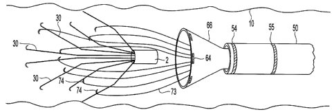
[0010] FIG. 1 is a perspective view of a blood filter.
{0011] FIG. 2 is a side view of a catheter suitable for use with an embodiment
filter
5 extraction system.
[0012] FIG. 3 is a side perspective view of a tubular member that preferably
forms
part of an embodiment filter extraction system.
[0013] FIG. 4 is a side perspective of a filter extraction member that
preferably forms
part of an embodiment filter extraction system.
100141 FIG. 5A through 5E are detail perspective views of hooking or snaring
elements of the extraction member illustrated in FIG. 4.
100151 FIG. 6 is a side perspective view of an embodiment of the filter
extraction
system at a stage of deployment prior to engaging a filter.
[0016] FIGS. 7A and 7B are side perspective views of an embodiment of the
filter
extraction system at later stages of deployment than that illustrated in FIG.
6.
[0017] FIG. 8 illustrates the positioning of the catheter shown in FIG. 2 near
a filter
within a blood vessel.
[0018] FIG. 9 illustrates a step in the process of extracting a blood filter
from a blood
vessel according to an embodiment.
[0019] FIG. l0A and 10 B illustrate subsequent steps in the process of
extracting a
blood filter from a blood vessel according to an embodiment.
[0020] FIG 11 A and 11B illustrate a fiarther step in the process of
extracting a blood
filter from a blood vessel according to an embodiment.
[.0021] FIG. 12 illustrates a still further step in the process of extracting
a blood filter
from a blood vessel according to an embodiinent.
CA 02633866 2008-06-10
WO 2007/079415 PCT/US2006/062733
6
[0022] FIG. 13 is a side perspective of a filter extraction member of an
alternative
embodiment filter extraction system.
[0023] FIG. 14 is a side perspective of a filter extraction member of an
alternative
embodiment filter extraction system.
[0024] FIG. 15 illustrates an alternative embodiment of the filter extraction
system.
[00251 FIG. 16 illustrates a step in the process of extracting a blood filter
from a
blood vessel according to the extraction system embodiment illustrated in FIG.
13.
[0026] FIG. 17 illustrates a subsequent step in the process of retracting a
blood filter
from a blood vessel according to the extraction system embodiment illustrated
in FIG. 13.
[0027] FIG. 18 illustrates a further step in the process of retracting a blood
filter from
a blood vessel according to the extraction system embodiment illustrated in
FIG. 13.
[0028] FIGS. 19A and 19B illustrate alternative embodiments of the filter
extraction
member.
Mode(s) For Carrying Out the Invention
[0029] The accompanying drawings and description represent the preferred
embodiments of the invention. Wherever possible, the same reference numbers
will be used
throughout the drawings to refer to the same or like parts.
[0030] As used herein, the terms "about" or "approximately" for any numerical
values or ranges indicate a suitable dimensional tolerance that allows the
part or collection of
components to function for its intended purpose as described herein. Also, as
used herein, the
terms "patient," "host" and "subject" refer to any human or animal subject and
are not
intended to limit the systems or methods to human use, although use of the
subject invention
in a human patient represents a preferred embodiment. Moreover, as used
herein, the term
"wire" refers to any elongated member of narrow cross section, including rods,
bars;.tubes,
CA 02633866 2008-06-10
WO 2007/079415 PCT/US2006/062733
7
ribbon and narrow sections cut from thin plate, and is not intended to limit
the scope of the
invention to elongated members of circular cross section, cut from wire stock
or
manufactured according to a particular method of metal forming.
[0031] The various embodiments of the blood filter extraction system are
configured
to engage and retract a typical blood filter from within a patient's blood
vessel, such as the
vena cava. A preferred blood filter 1 is illustrated in FIG. 1. Typically, a
blood filter
includes a number of filter members (e.g., wires) which both position and
anchor the filter
within a blood vessel and serve as the filtering elements which catch and
retain blood clots in
the blood.
[0032] Referring to FIG. 1, a filter 1 may include a plurality of anchor
members 30
which are positioned radially around the filter 1 and include hooks 40 which
hook into the
blood vessel wall to secure the filter within the vessel. A filter 1 may also
include locator
members 20 positioned radially around the filter and configured to press
radially outward
against the blood vessel wall to center the filter within the vessel. A filter
1 may also include
a hub 2 to which the locator members 20 and anchor members 30 are attached,
such as by
welding. When deployed within a blood vessel, the anchor members 30 preferably
form a
first conical filter basket while the locator members 20 further preferably
form a second filter
basket positioned downstream from the first filter basket. The hooks 40 may be
configured to
have a reduced cross section compared to the rest of the anchor or locator
members. By
reducing the cross sectional area of a portion or all of the hooks 40 relative
to that of the
anchor members 30 or locator members 20, stress will be concentrated in the
areas of reduced
cross section when longitudinal force is applied to the hub 2 in the direction
of blood flow BF
(i.e., towards the hub 2 of the filter) such as to remove the filter. Further
description of blood
filter configurations and constructions are provided in U.S. Patent 6,258,026,
and PCT
'Zn.ternatiorial Appllcation No. PCT/US06/01-7889, entitled "Removable Embolus
B'lood Clot
CA 02633866 2008-06-10
WO 2007/079415 PCT/US2006/062733
8
Filter," filed May 9, 2006, both of which are hereby incorporated by reference
in their
entireties. Also, descriptions of systems and methods used for implanting a
filter in a blood
vessel are provided in PCT International Application No. PCT/US06/17890,
entitled
"Embolus Blood Clot Filter and Delivery System," filed on May 9, 2006, which
is also
hereby incorporated by reference in its entirety.
[0033] When a filter 1, such as that illustrated in FIG. 1, has been in place
within a
blood vessel for a few weeks, the endothelial layer will tend to grow over the
portions of the
anchors 30, in particular the hooks 40, and the locator members 20 in contact
with the vessel
wall. This endothelial overgrowth helps to hold the filter 1 in position, but
may create
difficulties for extraction procedures. To avoid this, it is preferable to
depress the filter
members 20, 30 (i.e., anchors and locators) toward the vessel centerline
before the filter is
moved longitudinally through the vessel. Accordingly, preferred embodiments of
the blood
filter extraction system first engage the filter members with an extraction
wire and then
radially collapse the filter members away from the vessel walls and into a
catheter before the
catheter is withdrawn from the blood vessel.
[0034] One preferred embodiment of the blood filter extraction system includes
an
extraction member (embodiments of which are illustrated in FIGS. 4, 13 and
14), which is
preferably configured to be delivered to the vicinity of the filter 1 by a
catheter 50 (illustrated
in FIG. 2). In some embodiments, an elongated tubular member (illustrated in
FIG. 3)
featuring a conical distal end is also used to help collapse the filter
members when the
catheter is pressed over the conical end.
[0035] The filter extraction system uses a catheter to gain access to the
filter within a
vessel and withdraw it from the patient's body. A standard medical catheter of
about 7 to 10
French diameter may be used. In an embodiment illustrated in FIG. 2, a
catheter 50 is
provided as part of the filter .extraction system that: iricludes
eleriments:wwhich facilitate the
CA 02633866 2008-06-10
WO 2007/079415 PCT/US2006/062733
9
filter extraction process. Referring to FIG. 2, the catheter 50 has a diameter
D l which may
be that of a 7 to 10 French diameter catheter, though larger and smaller
catheters may also be
used. The catheter 50 features an exterior surface 51 and an internal surface
52 defining an
internal lumen 53. The catheter 50 is preferably about 45 inches long,
although longer and
shorter catheters may be used depending upon the size of the patient, the
location of the blood
filter to be extracted and the particular point of entry into the body to be
used.
[0036] The catheter 50 may also include one or more radio-opaque markers 54
and 55
that can be easily imaged by radiography or fluoroscopy to permit a clinician
to accurately
determine the position of the catheter within a patient's body. In the
embodiment illustrated
in FIG. 2, two radio-opaque markers 54 and 55 are used, the first
circumferential marker 54
located close to the distal end of the catheter 50, at length L1 from the end,
and a second
circumferential marker 551ocated length L2 from the first marker 54. In a
preferred
embodiment, length Ll ranges from approximately 0.01 inch to approximately 0.5
inch, and
length L2 ranges from approximately 0.5 inch to approximately 2 inches. As
used herein, a
radio-opaque marker is any material that is identifiable to machine or human-
readable
radiographic equipment while the material is inside a mammal body, such as, by
way of
example but not by way of limitation, gold, platinum, barium sulfate, or
tantalum. The use of
one marker allows a clinician to determine the location of a retrieving
catheter tip. But two
radio-opaque markers located a known distance apart can be utilized to allow
the clinician to
locate a delivery catheter within a blood vessel of the patient and accurately
estimate the
distance between the catheter's distal end and a filter. For example, the
distance L2 between
the first 54 and second 55 markers can be used as a distance scale when the
filter and catheter
are both imaged by fluoroscopy. To facilitate locating the catheter near the
filter, the filter
hub 2 can include a radio-opaque marker, such as by including a radio-opaque
element in the
hub material or coupling a radio-opaque marker to orwithin the -hub 2.
CA 02633866 2008-06-10
WO 2007/079415 PCT/US2006/062733
[0037] In use, the catheter 50 may be introduced into a patient via an
incision into a
major vein, such as the jugular vein, or artery, such as the femoral artery,
and advanced
through the blood vessel 10 to the vicinity of the filter 1, as illustrated in
FIG. 8. As
mentioned above, the clinician may use fluoroscopy to confirm that the
catheter 50 is
5 positioned at a proper distance away from the filter 1. In this position, a
clinician may
advance an ultrasound imager (not shown) or a fiber optic imager (not shown)
through the
catheter 50 to inspect the filter to determine if extraction is required or to
inspect the filter in
preparation for extraction. Saline solution may be provided through the
catheter 50 to
displace blood in order to facilitate imaging by a fiber optic imager.
10 [0038] The catheter may be formed of any materials used for medical
catheters,
including by way of example polyurethane, polyethylene, polyamide, polyether
block amide
(PEBA), nylon, and combinations thereof.
[0039] In an embodiment illustrated in FIG. 3, an elongated tubular member 60
may
be advanced through the catheter 50 to the vicinity of the filter.
Alternatively, the elongated
tubular member 60 may be positioned within the catheter 50 when the catheter
is introduced
into the patient. The tubular member 60 has a diameter D2, which is preferably
slightly
smaller than the internal diameter of the catheter 50 in which it is to be
inserted. The tubular
member 60 has an exterior surface 61 and an interior surface 62 defining an
inteznal lumen
63, and a conical portion 66 defined by a radius R2 at the distal end 67. The
tubular member
60 is preferably longer than the catheter 50 so that it can be manipulated by
the clinician from
the proximal end extending out of the catheter 50. In an embodiment, the
tubular member
may include radio-opaque markers 64, 65, located, for example, near the distal
end 67
(markers 64) and a distance L3 from the distal end 67 (markers 65). The radio-
opaque
markers 64, 65 may be separated by a known distance L4 to facilitate
determining the
position of the conical end 66 with respect to the' filter using flu.oroscopy.
In -various
CA 02633866 2008-06-10
WO 2007/079415 PCT/US2006/062733
11
embodiments, the radius R2 may range from approximately 0.25 inches to
approximately
0.75 inches, the distance L4 may range from between approximately 0.01 inch
and
approximately 0.25 inch, and distance L3 may range from between approximately
0.5 inch
and approximately 2 inches.
[00401 In order to permit the conical portion 66 to fit within the catheter
50, the
tubular member 60 may include folds 68, which may be strips or zones of
reduced thickness,
along which the conical portion 66 preferentially folds or collapses. Radio-
opaque markers
64 near the distal end 67 may be provided in arc segments as illustrated so
that when the
conical portion 66 is positioned within the catheter 50 the portions form an
approximately
continuous circumferential marker.
[00411 The tubular member may be formed of any materials used for medical
catheters, including by way of example polyurethane, polyethylene, polyamide,
polyether
block amide (PEBA), nylon, and combinations thereof.
[0042] FIG. 4 illustrates an embodiment of the extraction member 70. An
extraction
member 70 has a long wire or rod 71 which will be longer than the catheter 50
and the
tubular member 60 so that it can be manipulated by a clinician when in place.
A handle may
be provided on a proximal end to facilitate manipulation of the extraction
member 70 by a
clinician. A transition plug or hub 72 may be positioned at or near the distal
end of the
extraction member rod 71. This plug or hub 72 is coupled, such as by welding,
brazing or
swaging, to a plurality of extraction wires 73 extending therefrom in a distal
direction. Each
of the plurality of wires 73 may be tipped with a coupler 74 which is fu.rther
preferably
configured as a bend, loop or hook. The plurality of wires 73 may be of the
same or different
lengths preferably ranging from approximately 0.5 inch to approximately 1.5
inch, and may
be configured to bend away from the centerline of the extraction member 70 in
a conical.
fashion.when:unconstrained. In order to pexmit imaging of the extraction
member by
CA 02633866 2008-06-10
WO 2007/079415 PCT/US2006/062733
12
fluoroscopy, the plug or hub 72 may include or be made of a radio-opaque
material. To
further aid in locating the extraction member 70 within a patient by
fluoroscopy, a second (or
more) radio-opaque marker 75 may be separated by a known distance L5. In an
embodiment,
the distance L5 between approximately 0.5 inches and approximately 2 inches.
[00431 It is noted that the plug or hub 72 can be a generally tubular member
with a
central lumen to allow for passage of a guidewire, contrast agent, saline or
other members to
be delivered to the tips of the wires 73. The couplers 74 on the tips of the
plurality of wires
73 may be configured to increase the probability that they snare the locator
and anchor
members of the blood filter. To accomplish this, the couplers may be
configured as a hook
having a radius R3 that is approximately 1 to 3 times the diameter of the
filter member wires.
Further, the hooks may be off center and/or canted at an angle to the
centerline of the wires as
illustrated in FIGS. 5A, 5B and 5C, to increase the probability that the hooks
will snare one
or more filter wires when positioned among the filter members. Additionally,
while the
couplers 74 are shown as different types of hooks in Figures 5A-5C, other
forms of couplers
can be used.
[0044] For example, the generally spheroidal member shown in Fig. 5D can
replace
the hooks or other couplers where the outer diameter of the spheroidal member
is smaller
than a gap between any two adjacent locators or anchors of the blood filter.
With the
spheroidal members, the withdrawal of the wires 73 will cause the spheroidal
members to
move towards the longitudinal axis and come into contact with each other while
retaining the
portions of the filter proximal of the spheroidal members. Moreover, another
foreseeable
form of the couplers can be a single loop type, e.g., a snaring hoop shown in
Fig. 5E, to
capture the proximal portion (e.g., hub) of the filter and locate such portion
in a volume
defined by the retrieving cone.
CA 02633866 2008-06-10
WO 2007/079415 PCT/US2006/062733
13
[00451 The extraction member rod or wire 71 may be fabricated of a solid wire,
bar or
tube of a material, such as stainless steel, with a sufficiently high modulus
of elasticity to
permit the extraction member 70 to be pushed through the elongated tubular
member 60
and/or the catheter 50 without kinking and to be rotated within the elongated
tubular member
60 and/or the catheter 50 without twisting or kinking. The plurality of wires
73 may be made
from a metal such as stainless steel, or more preferably a shape memory alloy
such as, for
example, Nitinol preferably having an austenite finish (Af) temperature below
body
temperature. Wires 73 made from Nitinol may be annealed in the desired conical
configuration to establish that configuration as the wires' memory shape. So
formed, the
Nitinol wires 73 may be folded into a form that will fit within the elongated
tubular member
60 and/or catheter 50.
[00461 In use, an embodiment of the elongated tubular member 60 may be
advanced
within the catheter 50 until the conical portion 66 extends beyond the distal
end of the
catheter 50, as illustrated in FIG. 6. Thus projecting from the catheter
allows the conical
portion 66 to be used to envelop the hub of a filter making it easier to
engage the filter in a
blood vessel. Also, the combination of radio-opaque markers on the conical
portion (marker
64) and on the catheter (markers 54, 55) help a clinician to position the
assembly near the
filter using fluoroscopy. By comparing the distance between the radio-opaque
markers 64 on
the conical portion 66 and the catheter distal end radio-opaque marker 54 with
the known
distance between the radio-opaque markers 54, 55 on the catheter 50, the
clinician can
determine with fluoroscopy when the elongated tubular member 60 has been
advanced
sufficiently to allow full expansion of the conical portion 66 and/or when the
conical portion
66 has encompassed the filter.
[0047] In use, an embodiment of the extraction member 70 may be advanced
within.
-the elongated tubular merimber 60 so, that the plurality of wires 73 -extend~
within the .conical.
CA 02633866 2008-06-10
WO 2007/079415 PCT/US2006/062733
14
member 66 as illustrated in FIG. 7A. In an alternative embodiment, the
extraction member
70 may be advanced within the elongated tubular member 60 so that the
plurality of
extraction wires 73 extend beyond the conical member 66 as illustrated in FIG.
7B.
[0048] With the embodiments assembled in the configurations illustrated in
FIGS. 7A
and 7B, the filter extraction assembly is ready for engaging and extracting a
filter. These
configurations may be assembled through a number of alternative structural
and/or methods
of use embodiments. Examples of these alternative structure and assembly/use
method
embodiments are described below.
[0049] In one embodiment, the catheter 50 is first positioned near a filter in
a blood
vessel as illustrated in FIG. 8, the elongated tubular member 60 is next
advanced through the
catheter 50 until the conical portion 66 deploys as illustrated in FIG. 6, the
extraction member
70 is then advanced through the elongated tubular member 60 until the
plurality of wires 73
extends into the conical portion 66, as illustrated in FIG. 7A or beyond the
conical portion 66,
as illustrated in FIG. 7B. This embodiment of assembly permits a clinician to
use the catheter
50 to inspect the filter prior to preparing to remove it.
[00501 In another embodiment, the extraction member 70 may be positioned
within
the elongated tubular member 60 during fabrication, so that in use, the
clinician first positions
the catheter 50 near a filter 1 in a vein as illustrated in FIG. 8, followed
by advancing the pre-
assembled elongated tubular member 60 and extraction member 70 through the
catheter 50
until the conical portion 66 deploys as illustrated in FIGS. 6 and 7A.
Finally, the extraction
member 70 may be advanced a small distance to extend the plurality of wires 73
beyond the
conical portion 66 as illustrated in FIG. 7B. This embodiment facilitates
advancing the
extraction member 70 within the catheter 50 since the plurality of wires 73
are enclosed
within the conical portion 66 so they will not bind in the catheter.
CA 02633866 2008-06-10
WO 2007/079415 PCT/US2006/062733
[0051] In yet another embodiment, the extraction member 70 may be positioned
within the elongated tubular member 60 which is positioned within the catheter
50 during
fabrication as an extraction system. In this embodiment, the extraction member
70 and
elongated tubular member 60 are initially positioned within the catheter 50.
In use, the
5 assembled extraction system is first advanced within a vein by the clinician
until it is
positioned near the filter. Then the tubular member 60 and extraction member
70 are distally
advanced within the catheter 50 until the conical portion 66 extends as
illustrated in FIG. 6
and 7A. Finally, in an embodiment, the extraction member 70 may be distally
advanced
within the elongated tubular member 60 as illustrated in FIG. 7B.
10 [0052] Once the filter extraction assembly of one of the prior embodiments
is
deployed near the filter, the plurality of wires 73 are pressed into the
filter members 20, 30 so
the hooks on the wires can engage the filter locator and/or anchor members, as
illustrated in
FIGS. 9 and 10A. So engaged, the filter members can be pulled toward the
centerline of the
vessel and away from the wall by rotating the extraction member 70, as
illustrated in FIG.
15 l OB. Filter members 20, 30 can also be retracted by encompassing them
within the conical
portion 66 of the elongated tubular member 60. This may be accomplished by
holding the
extraction member 70 fixed while pushing the elongated tubular 60 member in a
distal
direction to position the conical portion 66 around the filter, including the
filter members. To
collapse the conical portion 66 over filter, the catheter 50 is pushed in the
distal direction
while holding the extended tubular member 60 and the extraction member 70
fixed. This is
illustrated in FIGS. 1 lA and 11B. As the catheter 50 pushes over the conical
member 66, the
conical member 66 collapses inward pressing against the filter members 20, 30,
further
pulling the filter members away from the vessel wall. The conical portion 66
also covers the
filter anchor hooks 40 so that they can be pulled into the catheter without
catching on the
CA 02633866 2008-06-10
WO 2007/079415 PCT/US2006/062733
16
vessel wall or the catheter. Finally, the filter 1 may be pulled fully into
the catheter, as
illustrated in FIG. 12, after which the catheter may be withdrawn from the
patient's body.
[0053] An alternative embodiment of the filter extraction assembly is
illustrated in
FIGS. 13-18. In this embodiment, instead of a plurality of wires 73, one or a
few extraction
wires 80 coupled to the hub 72 are formed in a helical shape, preferably a
conically shaped
helix as illustrated in FIG. 13. When the helical extraction wire 80 is
positioned over the
filter, the extraction member 70 can be rotated in the direction of the helix,
perhaps with
some distal motion of the extraction member 70. As a result of this rotational
motion, the
helical extraction wire 80 encircles the filter members 20, 30 in a screw
fashion, drawing the
filter members in toward the centerline of the helix and toward the extraction
member hub 72,
thereby releasing the filter members from the blood vessel walls and securely
attaching the
helical extraction wire 80 to the filter.
[0054] In the embodiment illustrated in FIG. 13, the helical extraction wire
80 is
formed in a conical shape with the narrow end of the cone coupled to the hub
72 of the
extraction member 70. The conical helix shape may be characterized by its
longitudinal
extension length L6 between the hub 72 and the open distal end 81, its conical
angle 0 of the
outside contour 83 to the centerline 82 of the helix and extraction member 70,
and the
number of rotations about the centerline 82 (i.e., density of the helix). This
embodiment
allows the extraction wire 80 to assist in positioning the extraction assembly
over a filter
since the broad open end 81 will engage the filter across an area larger than
the cross section
of the catheter. Rotation of the extraction wire 80 will draw the wire and the
filter into
centerline alignment. With fiuther rotation, the helix and filter members 20,
30 become more
tightly entangled, collapsing the extraction wire 80 about the filter so the
captured filter can
be drawn into the catheter 50.
CA 02633866 2008-06-10
WO 2007/079415 PCT/US2006/062733
17
[0055] In an alternative embodiment illustrated in FIG. 14, multiple helical
extraction
wires 80A, 80B are coupled to the hub 72 of the extraction member 70. FIG. 14
shows two
helical extraction wires 80A and 80B, but three, four or more wires may be
used. Preferably,
the multiple helical wires are equiangularly offset about the centerline. For
example,
embodiments employing two helical wires will be rotationally oriented 180
degrees one from
the other, and embodiments employing three helical wires may be rotationally
oriented 120
degrees apart. Embodiments employing multiple helical wires 80 may more easily
capture
filter members since each rotation will pass more wires through the filter
members 20, 30.
Alternatively, the cross section of a single helical wire can be varied to
achieve different
stiffness.
[0056] The embodiments illustrated in FIGS. 13-18 may utilize a catheter 50
and
elongated tubular member 60 similar to those used with other embodiments. In
embodiments
employing an elongated tubular member 60, the helical extraction wire 80 may
be contained
within the conical portion 66, as illustrated in FIG. 15. In this
configuration, the conical
portion 66 will prevent the helical extraction wire 80 from scratching or
digging into the
walls of the blood vessel. Also, the conical portion 66 and the helical
extraction wire 80 may
work in combination to position the filter near the centerline 82.
Consequently, the conical
angle 0 of the helical extraction wire 80 may be narrow (such as between
approximately
parallel to the centerline to approximately 30 degrees) since the conical
portion 66 will direct
the filter and extraction wire towards each other to facilitate engaging the
filter members. In
the preferred embodiment, the wire 80 utilizes an atraumatic tip (e.g., a
rounded loop, soft tip,
cone or sphere).
[0057] In an alternative embodiment, the conical form of the helical
extraction wires
80 may permit eliminating the elongated tubular member 60 since the conical
form of the
wires may perform the filter locating function otherwise-performed by the_
conical:portion 66:
CA 02633866 2008-06-10
WO 2007/079415 PCT/US2006/062733
18
Further, as the conical helix 80 is rotated, the wires may draw the filter
toward the hub 72 and
the filter members 20, 30 toward the centerline. In order to reveal the
functioning of the
helical extraction wire 80 this embodiment is illustrated in FIGS. 16-18.
[0058] In use, the catheter 50 is positioned near the filter 1 within a blood
vessel 10,
as illustrated in FIG. 8, and the extraction member 70 is advanced in a distal
direction until
the helical extraction wire 80 is clear of the distal end of the catheter 50.
The extraction
member 70 may be advanced to pass the helical extraction wire 80 at least
partially over the
filter, as illustrated in FIG. 16. In this configuration, the clinician
rotates the extraction
member 70 by rotating a handle on the proximal end. Rotational motion causes
the helical
extraction wire 80 to pass through the locator members 20 and anchor members
30, pulling
the filter members and the wire 80 in toward the centerline 82, as illustrated
in FIG. 17.
Moving the anchor members 30 toward the centerline causes their hooks to
become
disengaged from the vessel walls 10 without tearing the endothelial layers,
including the
endothelial overgrowth. Once the anchor members 30 have been pulled away from
the vessel
walls, the filter may be drawn into the catheter 50, as illustrated in FIG.
18, by either
advancing the catheter in the distal direction while holding the extraction
member 70 in a
fixed position, or pulling the extraction member 70 in the proximal direction
while holding
the catheter steady. Once the filter is pulled within the catheter, the
catheter may be
withdrawn from the patient. Alternatively, the extraction member 70 is not
rotated, but
instead translated so that the member 70 encircles a substantial portion of
the filter.
Extraction of the filter can be obtained by moving the catheter 50 and member
70 relative to
each other. For example, the catheter 50 may be moved distally away from the
clinician
while maintaining the extraction member 70 generally stationary; the
extraction member 70
and catheter 50 may be moved toward each other; or the extraction member 70
may be
'moved proximally while maintaining the catheter.50 stationary. Additionally,
the. lielical
CA 02633866 2008-06-10
WO 2007/079415 PCT/US2006/062733
19
member can be formed so that its austenite transformation finish temperature
Af is greater
than 37 degrees Celsius and preferably greater than 42 degrees Celsius so that
warm saline
(e.g., at greater than 37 degrees Celsius) can be utilized to clamp the
helical member down on
the filter once the helical member is in position proximate the filter.
[0059] In alternative embodiments illustrated in FIGS. 19A and 19B, the
elongated
tubular member 60 may be eliminated by coupling a flexible conical portion 76
to the
extraction member 70, such as at the distal hub or node 72. In this
embodiment, the conical
portion 76 may be made of a flexible polymer material, such as polyurethane,
polyethylene,
polyamide, polyether block amide (PEBA), nylon, and combinations thereof, and
coupled to
the hub 72 by a bio-compatible adhesive, e.g., cyanoacrylates. The conical
portion 76 may
include folds or thinned sections (such as, for example, folds 68 illustrated
in FIG. 3) to
permit the cone to be collapsed in order to fit into a catheter. In use, the
conical portion 76
may be deployed by holding the catheter in a fixed position while pushing on
the proximal
end of the extraction member 70 until the distal end extends from the
catheter. Once
deployed from the catheter the conical portion 76 is pushed over the filter so
the plurality of
wires 73 or the helical extraction wire 80 engage the filter members 20, 30.
By rotating the
extraction member 70, the filter members may be pulled away from the vessel
walls. At this
point, the conical portion 76 may be used to encircle the filter by pushing
the catheter over
the filter without moving the extraction member 70 in a manner similar to the
methods of use
described above.
[0060] Several design features are believed to be important in advancing the
state of
the art. For example, the use of extraction wires 73, 80 to engage the filter
members enables
pulling the filter anchor members 30 away from the vessel wall 10 before
moving the filter.
This is believed to help engage the filter hub 2 with the retrieving cone.
Also, the use of
25. extraction wires 73; 80 to engage the fzlter -member enables safe removal
of a filter that is not
CA 02633866 2008-06-10
WO 2007/079415 PCT/US2006/062733
configured (e.g., with a removal hook) to be removable. Also, the use of an
extraction
member with extraction wires 73, 80 to engage the filter members enables a
clinician to
securely latch onto the filter before the conical portion 66, 76 is collapsed
over the filter and
is retracted into the catheter. Also, the use of an extraction member 70 that
is separate from
5 the elongated tubular member 60 permits the clinician to manipulate the
filter grappling wires
73, 80 separately from the conical portion 66 of the tubular member 60.
Further, the use of
the couplers (e.g., hooks, spheres, loops) allow for locatirig of the filter
in the volume defined
by the retrieval cone so that the cone can be utilized to collapse the filter
into a smaller
configuration suitable for retrieval.
10 [0061] Although the preferred embodiments have been shown and described in
relation to the filter of Figure 1, other filters can also be utilized in
conjunction with the
removal system described herein as long as these filters are collapsible to a
smaller radial
configuration. For example, the removal system may be provided for the filter
shown and
described in U.S. Patent No. 4,425,908, which is hereby incorporated by
reference in its
15 entirety. The system may also be provided for the filter shown and
described in U.S. Patent
No. 6,443,972, which is also hereby incorporated by reference in its entirety.
Commercially
available filters that are collapsible may also be utilized with the filter
removal system
described. These commercially available filters include but are not limited to
the
Gxeenfield Filter, VenaTech Filter, Gunther Tulip Filter, TrapEase or
OptEase .
20 [0062] While the present invention has been disclosed with reference to
certain
preferred embodiments, numerous modifications, alterations, and changes to the
described
embodiments are possible without departing from the sphere and scope of the
present
invention. Accordingly, it is intended that the present invention not be
limited to the
described embodiments, but that it has the full scope defined by the language
of the following
' clainis, and equivalents thereof.