Note: Descriptions are shown in the official language in which they were submitted.
CA 02635638 2008-07-17
WO 2007/082389 PCT/CA2007/000087
METHOD AND SYSTEM FOR ASSESSING
ATHLETIC PERFORMANCE
Cross Reference to Related Application
[0001] This application claims the benefit of the filing date of U.S.
patent application No. 60/760,380 filed on 20 January 2006 and entitled
"METHOD AND SYSTEM FOR ASSESSING ATHLETIC
PERFORMANCE".
Technical Field
[0002] This invention relates to methods and systems for assessing
athletic performance. In particular, this invention relates to methods
and systems for collecting acceleration and rotation data and extracting
features which relate to athletic performance therefrom.
Background
[0003] In high performance sport, it is common for an athlete to
work closely with a trainer. The role of the trainer is to assist the
athlete in physical conditioning. The trainer often measures the
physical performance of the athlete and recommends training regimes
based on this information.
[0004] There are a number of prior art devices which may be used
to monitor the motion of a person or other subject. For example, U.S.
patent No. 5,955,667 to Fyfe discloses a device comprising a pair of
accelerometers and a tilt sensor mounted in fixed relation to a datum
defining plane such as the sole of a shoe. The device disclosed by Fyfe
maybe used for extracting kinematic variables including linear and
rotational acceleration, velocity and position.
[0005] U.S. patent No 6,305,221 to Hutchings discloses a device
that measures the distance traveled, speed, and height jumped of a
person while running or walking. The device comprises accelerometers
CA 02635638 2008-07-17
WO 2007/082389 PCT/CA2007/000087
-2-
and rotational sensors positioned in the sole of a shoe along with an
electronic circuit that performs mathematical calculations to determine
the distance and height of each step. A transmitter sends the distance
and height information to a central receiving unit which comprises a
microprocessor which outputs the distance traveled, speed, or height
jumped of the runner or walker to a display.
[0006] There exists a need for methods and systems which provide
more information about athletic performance.
Summary
[0007] The following embodiments and aspects thereof are
described and illustrated in conjunction with systems, tools and methods
which are meant to be exemplary and illustrative, not limiting in scope.
In various embodiments, one or more of the above-described problems
have been reduced or eliminated, while other embodiments are directed
to other improvements.
[0008] One aspect of the invention provides a system for assessing
athletic performance comprises a mounting device wearable by an
athlete, a sensing device attachable to the mounting device, and a base
unit. The sensing device comprises acceleration sensors for measuring
acceleration data during an athletic test to produce at least three
acceleration signals, rotation sensors for measuring rotation data during
the athletic test to produce at least three rotation signals, signal
conditioning hardware for conditioning the acceleration and rotation
signals and sampling the acceleration and rotation signals at a sampling
rate to produce acceleration and rotation data, and, a wireless
communication device for transmitting the acceleration and rotation
data. The base unit comprises a wireless communication device for
receiving the acceleration and rotation data, a feature extractor for
CA 02635638 2008-07-17
WO 2007/082389 PCT/CA2007/000087
-3-
extracting features relating to athletic performance from the data based
on a plurality of expected events of the athletic test, and, an output
device for outputting the extracted features.
[0009] Another aspect of the invention provides a method for
assessing athletic performance of a living subject. The method
comprises providing at least three acceleration sensors on the subject
configured to measure acceleration along three local axes, providing at
least three rotation sensors on the subject configured to measure rotation
about the three local axes, monitoring the acceleration sensors and the
rotation sensors to produce acceleration data and rotation data,
determining an orientation of the three local axes based on the measured
rotation data, applying a rotation function to the measured acceleration
data based on the determined orientation of the three local axes to
generate corrected acceleration data along three global axes, receiving a
test identification specifying a plurality of expected events, extracting
features relating to athletic performance of the subject by detecting
events corresponding to the expected events in the corrected
acceleration data, and, outputting the extracted features.
[0010] In addition to the exemplary aspects and embodiments
described above, further aspects and embodiments will become apparent
by reference to the drawings and by study of the following detailed
descriptions.
Brief Description of Drawings
[0011] Exemplary embodiments are illustrated in referenced
figures of the drawings. It is intended that the embodiments and figures
disclosed herein are to be considered illustrative rather than restrictive.
CA 02635638 2008-07-17
WO 2007/082389 PCT/CA2007/000087
-4-
[0012] In drawings which illustrate non-limiting embodiments of
the invention:
Figure 1 shows a system for assessing athletic performance
according to one embodiment of the invention;
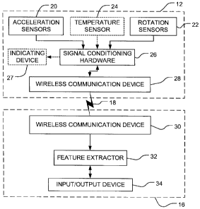
Figure 2 shows basic elements of a sensing device and a base unit
according to one embodiment of the invention;
Figure 3 shows a sensing device according to another
embodiinent of the invention;
Figure 4 shows a sensing device according to another
embodiment of the invention;
Figure 5 shows a base unit according to another embodiment of
the invention;
Figure 6 shows a system for assessing athletic performance
according to another embodiment of the invention;
Figure 7 is a flowchart illustrating steps in a method according to
one embodiment of the invention;
Figures 8A-E are graphical representations of example
acceleration data from a jump test as it is processed by a method
according to one embodiment of the invention;
Figure 8F is a graphical representation of velocity data obtained
from the example acceleration data of Figure 8E;
Figure 9 is a flowchart illustrating steps in a method of extracting
features from acceleration data according to one embodiment of the
invention;
Figure 10 shows features extracted from the example acceleration
and velocity data of Figures 8E and 8F by a method according to one
embodiment of the invention;
Figure 11 shows example acceleration and rotation data from a
running test;
Figure 12 is a flowchart illustrating steps in a method of assessing
athletic performance according to another embodiment of the invention;
CA 02635638 2008-07-17
WO 2007/082389 PCT/CA2007/000087
-5-
Figure 13 shows an example input/output device according to one
embodiment of the invention; and
Figure 14 shows an example feature extractor according to one
embodiment of the invention.
Description
[0013] Throughout the following description specific details are set
forth in order to provide a more thorough understanding to persons
skilled in the art. However, well known elements may not have been
shown or described in detail to avoid unnecessarily obscuring the
disclosure. Accordingly, the description and drawings are to be
regarded in an illustrative, rather than a restrictive, sense.
[0014] The invention provides systems and methods for assessing
athletic performance. Some embodiments provide a system for
collecting data relating to movement of a subject such as, for example
an athlete. The system may collect data generated during a test period
when the athlete performs a predetermined action or series of actions,
and may extract features relating to athletic performance from the
collected data.
[0015] Figure 1 illustrates a system 10 according to one
embodiment of the invention. System 10 comprises a sensing device 12
attachable to a mounting device 14. Mounting device 14 may comprise,
for example, a belt, strap or the like which may be worn by an athlete.
When in use by an athlete, mounting device 14 may hold sensing device
12 at the small of the athlete's back, since this position is near the
athlete's centre of mass and does not impede many athletic activities.
However, sensing device 12 may be positioned at another location on
the athlete's torso.
CA 02635638 2008-07-17
WO 2007/082389 PCT/CA2007/000087
-6-
[0016] Sensing device 12 communicates with a base unit 16 by
means of a wireless communication link 18. Base unit 16 may
comprise, for example, a personal digital assistant (PDA), a computer,
or any other electronic device with suitable data processing capabilities
and a communication link.
[0017] In operation, an athlete mounts sensing device 12 on his or
her body by means of mounting device 14 and performs an action or
series of actions (referred to herein as a "test") designed to assess
athletic performance. Sensing device 12 records data during the test,
and provides the recorded data to base unit 16. Base unit 16 is also
provided with a user-selected identification of the test to be performed
by a user such as a trainer, coach, or in some embodiments the athlete
who performs the test. Base unit 16 processes the data received from
sensing device 12 based on the user-selected test identification to extract
features relating to athletic performance. In some embodiments, some
data processing is also done by sensing device 12. Base unit 16
provides the extracted features to the user by means of an output device,
as discussed further below.
[0018] Figure 2 schematically depicts components of sensing
device 12 and base unit 16 according to one embodiment of the
invention. Sensing device 12 comprises a plurality of acceleration
sensors 20 and a plurality of rotation sensors 22. Acceleration sensors
20 are configured to measure acceleration along each of three local axes
and produce at least three acceleration signals which contain
acceleration data. Rotation sensors 22 are configured to measure
rotation around each of three local axes and produce at least three
rotation signals which contain rotation data. The three local axes are
referred to herein as the X-axis, Y-axis and Z-axis.
CA 02635638 2008-07-17
WO 2007/082389 PCT/CA2007/000087
-7-
[0019] If acceleration sensors 20 and/or rotation sensors 22 are
sensitive to temperature, sensing device may optionally comprise at
least one temperature sensor 24 (indicated in dotted lines in Figure 2).
Temperature sensor 24 is configured to measure the temperature of
acceleration sensors 20 and/or rotation sensors 22 and produce at least
one temperature signal which may be used to compensate for variations
in the outputs of sensors 20 and/or 22 which may result from changes in
temperature.
[0020] Sensing device 12 also comprises signal conditioning
hardware 26 connected to acceleration sensors 20, rotation sensors 22
and temperature sensors 24 (if applicable). Acceleration sensors 20,
rotation sensors 22 and temperature sensors 24 may be analog or digital
sensors. If analog sensors are used, signal conditioning hardware may
comprise an analog to digital converter (ADC). Signal conditioning
hardware 26 is configured to sample the signals from acceleration
sensors 20, rotation sensors 22 and temperature sensors 24 at a
sampling rate suitable for the test to be performed. The sampling rate
may be as low as 50 Hz, but a higher sampling rate may be desirable in
some applications. In some embodiments, the sampling rate may be in
excess of 100 Hz, for example approximately 400 Hz. Signal
conditioning hardware 26 may also comprise, for example, low pass
filters for removing high frequency shocks from the signals.
[0021] Signal conditioning hardware 26 is connected to provide
data from the acceleration, rotation and temperature signals (if
applicable) to a wireless communication device 28. Wireless
communication device 28 is configured to transmit the data to a
compatible wireless communication device 30 associated with base unit
16. Wireless communication devices 28 and 30 may each comprise, for
CA 02635638 2008-07-17
WO 2007/082389 PCT/CA2007/000087
_$-
example, a radio frequency (RF) module having a line-of-sight range of
one kilometer.
[0022] Sensing device 12 may also optionally comprise an
indicating device 27 connected to sensor conditioning hardware 26.
Indicating device 27 may be operated by sensor conditioning hardware
26 to provide the athlete with a start signal directing the athlete to begin
a test. The start signal may comprise, for example, an audible signal, a
visual signal, an electrical signal (i.e., a mild shock), or a vibration
signal. Sensor conditioning hardware 26 may cause indicating device
27 to provide the start signal in response to a command received from
base unit 16 by means of wireless communication devices 28 and 30.
[0023] In addition to wireless communication device 30, base unit
16 comprises a feature extractor 32 and an input/output device 34.
Feature extractor 32 may comprise, for example, a signal processor
coupled to a memory. Input/output device 34 may comprise, for
example, a touch-sensitive display, a keyboard and monitor, or the like.
[0024] Feature extractor 32 is connected to receive the
acceleration, rotation and (if applicable) temperature data from wireless
communication device 30. Feature extractor 32 processes the data
received from wireless communication device 30 during an athletic test
to extract features related to athletic performance. Feature extractor 32
may be programmed with a plurality of expected events for each of a
plurality of predetermined tests. A user may select one of the
predetermined tests using input/output device 34. Feature extractor 32
may use the expected events for the test identified by the user to extract
features related to athletic performance from the data received from
sensing device 12. A user may also input provide feature extractor 32
CA 02635638 2008-07-17
WO 2007/082389 PCT/CA2007/000087
-9-
with the athlete's mass using input/output device 34. Feature extractor
32 may use the athlete's mass for extracting features relating to force or
power. The features extracted by feature extractor 32 may be provided
to a user, the athlete, and/or a data storage medium by means of
input/output device 34.
[0025] It is to be understood that each of sensing device 12 and
base unit 16 also comprise a suitable power source for providing
electrical power to the components thereof. The power sources have
not been shown to avoid cluttering the drawings.
[0026] Figure 3 shows a possible configuration of sensing device
12 according to one embodiment of the invention. In the Figure 3
embodiment, acceleration sensors 20 comprise six accelerometers 41-46
and rotation sensors 22 comprise three gyroscopes 47-49. Each of the
X-, Y- and Z-axes has two acceleration sensors and one rotation sensor
associated therewith. Accelerometers 41 and 42 measure acceleration
along the X-axis ` Accelerometers 43 and 44 measure acceleration along
the Y-axis. Accelerometers 45 and 46 measure acceleration along the
Z-axis. Gyroscope 47 measures rotation about the X-axis. Gyroscope
48 measures rotation about the Y-axis. Gyroscope 49 measures rotation
about the Z-axis.
[0027] Accelerometers 41, 43 and 45 each have range that is
relatively high in comparison to accelerometers 42, 44 and 46 and a
sensitivity that is relatively low in comparison to accelerometers 42, 44
and 46. For example, the range of accelerometers 41, 43 and 45 may
be 5g or more (where g represents the acceleration due to gravity at the
earth's surface, roughly 9.8 m/s2) and the sensitivity of accelerometers
41, 43 and 45 may be approximately 192 mV/g and the range and
sensitivity of accelerometers 42, 44 and 46 may be up to 2g and
CA 02635638 2008-07-17
WO 2007/082389 PCT/CA2007/000087
-10-
approximately 700 mV/g, respectively, although it is to be understood
that accelerometers having different ranges and sensitivities may be
used. The use of both high range and high sensitivity accelerometers
for each local axis allows sensing device 12 to measure large
accelerations and changes in acceleration while maintaining the ability
to accurately monitor smaller accelerations.
[0028] Gyroscopes 47-49 may each comprise a micro-electro-
mechanical system (MEMS) configured to measure a rate of rotation
about the associated axis. Each of gyroscopes 47-49 may have, for
example, a range of 600 /s and a sensitivity of approximately 5
mV/ /s. Gyroscopes 47-49 could each comprise a separate element, or
could be combined in a single chip. Alternatively, additional
accelerometers could be used instead of gyroscopes 47-49, since
rotational information may be provided by two accelerometers
positioned to measure acceleration along two spaced apart non-
perpendicular axes by using solid body rotation techniques known in the
art.
[0029] Figures 4 and 5 respectively show a sensing device 50 and
a base unit 80 of a system for assessing athletic performance according
to another embodiment of the invention. The embodiment of Figures 4
and 5 is shown for illustrative purposes, and includes a number of
features which are not required for the basic functioning of the system,
but which may be desirable in some applications.
[0030] Sensing device 50 comprises a plurality of accelerometers
52 for measuring acceleration data along three axes to produce at least
three acceleration signals and a plurality of gyroscopes 54 for
measuring rotation data about three axes to produce at least three
rotation signals. The signals from accelerometers 52 and gyroscopes 54
CA 02635638 2008-07-17
WO 2007/082389 PCT/CA2007/000087
-11-
are passed through a low pass filter array 56 in order to remove high
frequency noise from the signals. Low pass filter array 56 may
comprise, for example, second order operational amplifier-based active
filters having a cut off frequency of approximately 100 Hz.
[0031] In the Figure 4 embodiment, accelerometers 52 and
gyroscopes 54 produce analog signals. After the acceleration and
rotation signals are passed through low pass filter array 56, they are
converted to digital signals by an analog to digital converter (ADC) 58.
The digital signals from ADC 58 are provided to a processor 70. ADC
58 preferably has an internal clock and is configured to sample analog
signals at a suitable sampling rate. The sampling rate of ADC 58 may
be, for example, approximately 400 Hz. It is to be understood that
ADC 58 is not required in embodiments where digital sensors are used
instead of analog sensors. Alternatively, sensing device 50 could
provide analog signals to base station 80, in which case ADC 58 may
instead be located in base station 80.
[0032] Sensing device 50 may also comprise a plurality of
magnetometers 60 for measuring the earth's magnetic field in order to
produce a magnetic heading signal. Magnetometers 60 may comprise,
for example, at least three magnetometers. The magnetic heading
signal from magnetometers 60 may be used periodically to verify the
orientation of device 50 to compensate for drift which may be caused by
accumulation of errors in the rotation signals from gyroscopes 54 as the
rotation signals are integrated. Magnetometers 60 may each have, for
example, a range of 6 gauss and a sensitivity of approximately 5
mV/gauss. Alternatively, other means for compensating for drift may
be used instead of magnetometers 60, such as a gravitometer or a global
positioning system (GPS).
CA 02635638 2008-07-17
WO 2007/082389 PCT/CA2007/000087
-12-
[0033] Sensing device 50 may also comprise a pressure sensor 62.
Pressure sensor 62 measures barometric pressure to produce a pressure
signal which may indicate a change in altitude. Pressure sensor 62 may
have; for example, a range of 105 kPa and a sensitivity of
approximately 20 mV/kPa.
[0034] The signals from magnetometer 58 and pressure sensor 60
are also analog signals in the Figure 4 embodiment. The analog
magnetic heading and pressure signals may be passed through an
amplifier 64 before being provided to ADC 58. Amplifier 64 may
have, for example, a gain of 200 to improve the readability of the
magnetic heading and pressure signals by ADC 58.
[0035] Sensing device 50 may also comprise at least one
temperature sensor 66. Temperature sensor 66 is configured to
measure the temperature of any of accelerometers 52, gyroscopes 54,
magnetometer 60, and pressure sensor 62 which are temperature
sensitive and provide a temperature signal to ADC 58. A single
temperature sensor 66 may be positioned in a position which is in a
similar thermal environment to the other sensors of sensing device 50,
or multiple temperature sensors 66 may be provided, with one
positioned near each temperature sensitive sensor.
[0036] Sensing device 50 may also comprise a heart rate monitor
68. In the Figure 4 embodiment, heart rate monitor 68 produces a
digital heat rate signal which is provided directly to processor 70.
[0037] Processor 70 receives digital acceleration, rotation and
optionally other signals and controls the collection of acceleration,
rotation and other data over a test period. Processor 70 provides the
data to at least one of a memory 72, a USB interface 74 and a RF
CA 02635638 2008-07-17
WO 2007/082389 PCT/CA2007/000087
-13-
module 79. Memory 72 may be used to store data from a plurality of
tests so that an athlete or trainer may compare results from different
tests to track the athlete's progress. USB interface 74 allows processor
70 to be connected to exchange data with other computerized systems.
RF module 79 allows processor 70 to communicate with base station 80
(see Figure 5).
[0038] Processor 70 may also control the operation of a status
indicator 75. Status indicator 75 may comprise, for example, one or
more LEDs which may be selectively illuminated by processor 70 to
indicate the status of sensing device 50.
[0039] Processor 70 may also control the operation of an audio
device 77. Audio device 77 may be used to inform the test subject of
the beginning of a test. Processor 70 may receive instructions to initiate
a test from another processor 82 in base unit 80 by means of RF
modules 79 and 81 (see Figure 5).
[0040] As shown in Figure 5, base unit 80 comprises an
interactive display 84 connected to processor 82. Interactive display 84
may be controlled by software running on processor 82. Interactive
display 84 may be used by a user to initiate a test. Interactive display
84 may provide information about the test to a user. Processor 82 may
also optionally be connected to a USB interface 89 to allow processor
82 to exchange data with other computerized systems.
[0041] Figure 6 shows a system 90 for assessing athletic
performance according to another embodiment of the invention. System
90 comprises a plurality of acceleration sensors 92 and a plurality of
rotation sensors 94 connected to a signal processor 96. Signal
processor 96 collects acceleration and rotation data from acceleration
CA 02635638 2008-07-17
WO 2007/082389 PCT/CA2007/000087
-14-
and rotation sensors 92 and 94. Signal processor 96 extracts features
relating to athletic performance from the acceleration and rotation data
and provides the extracted features to an input/output device 98.
Input/output device 98 may comprise, for example, a wireless
communication device which communicates with a display.
[0042] System 90 may also comprise a memory 99. Signal
processor 96 may store the extracted features in memory 99. Memory
may also contain data relating to a plurality of predetermined expected
test events. The expected test events may be used by signal processor
96 in extracting the features relating to athletic performance.
[0043] Figure 7 is a flowchart illustrating a method 100 for
assessing athletic performance according to one embodiment of the
invention. Method 100 may be carried out by a processor such as, for
example, feature extractor 32 in the embodiment of Figures 1 and 2,
processor 70 or 82 in the embodiment of Figures 4 and 5, or signal
processor 96 in the embodiment of Figure 6. Method 100 may be
embodied in software stored in a memory accessible to the processor.
[0044] At block 102 the processor receives acceleration data and
rotation data collected over a test period during which an athlete
performs a test. The test period may be initiated by the processor by
providing the athlete with an indication that data is being collected. The
indication may be provided, for example, by means of input/output
device 34 in the Figure 2 embodiment, or by means of audio device 77
in the embodiment of Figures 4 and 5. During the test period, the
athlete performs a test comprising a predetermined action or series of
actions designed to assess athletic performance. The test period may
end after a predetermined amount of time, after the processor detects
CA 02635638 2008-07-17
WO 2007/082389 PCT/CA2007/000087
-15-
that the ath-lete has completed the predetermined action or series of
actions, or may be ended manually.
[0045] The test may comprise, for example, a single jump test, a
multiple jump test, a running test, a sprinting test, a gait analysis test,
an agility test, a balance test, a running vertical jump test, a triple jump
test, a long jump test, a high jump test, a pole vault test, a reaction time
test, a T-test, a zig-zag test, or any other action or series of actions
designed to test athletic performance. For each type of test, the
processor may be provided with an expected event or set of events
which should be represented by the data collected during the test period.
[0046] In some embodiments, the sensing device or base unit may
provide the athlete with instructions for the test. For example, for a
jump test, the sensing device or base unit may instruct the athlete to
remain motionless until they hear a tone, then jump straight up. In
some embodiments, the athlete is instructed to remain stationary for a
first stationary period immediately before the test and/or a second
stationary period immediately after the test. The amount of time the
athlete remains stationary before and after the test may be, for example
about 0.2 seconds. Data collected during the stationary period(s) may
be used to provide a baseline reference for the data collected during the
test. The start of a test may be indicated by an onset of acceleration.
[0047] The following description uses examples of a jump test and
a running test for illustrative purposes, but it is to be understood that
other types of tests may also be conducted according to certain
embodiments of the invention. Figure 8A shows example Z-axis
acceleration data from a jump test which is used to illustrate the
operation of method 100 in the following paragraphs.
CA 02635638 2008-07-17
WO 2007/082389 PCT/CA2007/000087
-16-
[0048] At block 104 the processor determines if all data for the
test has been received. The processor may determine if all data for the
test has been received by comparing the received data with an expected
data pattern and/or checking timing information which may be included
in the data. If all data for the test has not been received (block 104 NO
output), the processor requests the missing data at block 106 and the
steps of blocks 102 and 104 are repeated.
[0049] When all data for the test has been received (block 104
YES output), the processor applies a scaling function to the data at
block 108. At block 110 the processor corrects the data for sensor gain
and bias. Sensor gain an bias may be determined prior to the initiation
of method 100 by calibrating the sensors used to collect the data.
Figure 8B shows the example jump test Z-axis acceleration data of
Figure 8A after the scaling function has been applied and the data has
been corrected for gain and bias.
[0050] At block 112 the processor crops the data by detecting the
data corresponding to the stationary periods before and after the test,
and discarding data collected before and after the first and second
stationary periods, respectively. Figure 8C shows the example Z-axis
acceleration data after cropping.
[0051] At block 114 the processor determines an orientation of the
sensors used to collect the acceleration data based on the rotation data.
The processor then applies a rotation function to the acceleration data
based on the determined orientation to produce acceleration data along
three global axes. The global axes may comprise, for example, a
vertical axis, a lateral axis and a longitudinal axis. The processor then
subtracts g (the acceleration due to gravity) from the acceleration data
CA 02635638 2008-07-17
WO 2007/082389 PCT/CA2007/000087
-17-
along the vertical axis to produce global acceleration data. In the jump
test, the vertical axis may be referred to as the primary axis since
vertical acceleration data is primarily used to extract features relating to
athletic performance. Figure 8D shows the global vertical acceleration
data produced from the example acceleration data after the steps of
block 114.
[0052] At block 116 the processor applies boundary conditions to
the global acceleration data. For example, the processor may require
the global acceleration data to indicate zero acceleration over the
stationary periods and adjust all of the global acceleration data so that
zero acceleration is indicated for the stationary periods. Figure 8E
shows the global vertical acceleration data after the steps of block 116.
[0053] At block 118 the processor processes the global
acceleration data. For example, at block 118 the processor may
integrate the global acceleration data to produce global velocity data.
The integration performed by the processor may be, for example, a
numerical integration using the trapezoidal rule. Figure 8F shows the
global velocity data produced from the global acceleration data of
Figure 8E. Other examples of processing performed at block 118
include filtering the global acceleration data and differentiating the
global acceleration data. Filtration and/or differentiation of the global
acceleration data may be performed instead of or in combination with
integration of the global acceleration data.
[0054] At block 120 the processor extracts features relating to
athletic performance from the processed data. The processor extracts
the features based on a test identification which may be specified by a
user. The processor may extract the features by detecting a plurality of
expected events in the data, as described further below.
CA 02635638 2008-07-17
WO 2007/082389 PCT/CA2007/000087
-18-
[0055] At block 121 the processor outputs the extracted features.
The extracted features may be output, for example, by displaying one or
more graphs (e.g., acceleration, force, power, velocity, and/or position
versus time) or values (e.g., reaction time, preload time, maximum
force, etc.) on a display, as described further below.
[0056] Figure 9 is a flowchart illustrating one possible method of
extracting features in block 120 of Figure 7. At block 122 the
processor receives global acceleration and velocity data. At block 124
the processor receives a test identification which specifies the type of
test which was performed to produce the global acceleration and
velocity data. The test identification may include a plurality of expected
events. As indicated by the dashed box around blocks 122 and 124, the
order of these steps is not important.
[0057] At block 126 the processor detects events in the global
acceleration data which correspond to the expected events. Figure 10
illustrates some detected events in the example jump test vertical
acceleration data of Figures 8E and 8F. Event 130 corresponds to the
initiation of a jumping motion by an athlete flexing their legs and
moving their torso downwardly, and is characterized by the beginning
of a negative vertical acceleration. Event 132 corresponds to the
beginning of the athlete's upward push, and is characterized by a
transition from a negative to a positive acceleration. Event 134
corresponds to the point at which the athlete increases the development
of force, and is characterized by an increase in positive vertical
acceleration. Event 136 corresponds to the point at which the athlete's
toes leave the ground, and is characterized by a fast transition from a
positive acceleration to a negative acceleration. Event 138 corresponds
to the point at which the athlete's feet initially impact the ground, and is
CA 02635638 2008-07-17
WO 2007/082389 PCT/CA2007/000087
-19-
characterized by a fast transition from a negative acceleration to a large
positive acceleration. Event 140 corresponds to the end of the "impact
phase", and is characterized by a transition from positive to negative
acceleration. The time between two events may be determined from the
number of samples between these events and the sampling rate.
Although the illustrated example uses vertical acceleration data, it is to
be understood that global acceleration data for other axes, as well as
rotation data, may also be analyzed to detect expected events.
[0058] At block 128 the processor determine features relating to
athletic performance based on the detected events. Features which may
be determined for a jump test include:
= Reaction Time - the time between when an audible signal is
sounded to start the test and when the athlete begins to move;
= Jump Start - where the athlete begins moving down;
= Preload Time - the time the athlete takes to bend down;
= Start of Upwards Motion - where the athlete begins moving
upwards;
= Push-off Time - the time the athlete takes to push and reach
toe-off;
= Take-off Velocity - upward velocity at toe-off;
= Toe-off - where the athlete leaves the ground;
= Air Time - the time the athlete is in the air;
= Height Jumped - height that the athlete jumps;
(This feature may be determined based on either Air Time or Take-off
Velocity, or both, to provide for data verification. If the two
determinations differ by more than a predetermined amount, an error
signal may be generated.)
= Maximum Take-off Force - the maximum force generated in the
take-off phase (between "start of upwards motion" and
"toe-off");
CA 02635638 2008-07-17
WO 2007/082389 PCT/CA2007/000087
-20-
= Mean Take-off Force - the average amount of force generated in
the take-off phase;
= Maximum Take-off Power - the maximum power generated in the
take-off phase;
= Mean Take-off Power - the average amount of power generated
in the take-off phase;
= Maximum Rate of Force Development - the maximum rate that
force is developed in the take-off phase;
= Mean Rate of Force Development - the average rate of force
developed in the take-off phase;
= Ground Contact - where the athlete contacts the ground;
= End of Impact - the time from landing until athlete completes
landing and stops
= Impact Time - time between "Ground Contact" and "End of
Impact" ;
= Maximum Impact Force - the amount of force the athlete creates
upon landing; and,
= Mean Impact Force - the average amount of force in the landing
phase (between "ground contact" and "end of impact").
Methods and systems according to the invention may also be used to
extract features from data from a multiple test or a squatting jump test.
In a multiple jump test, the athlete performs a series of jumps. The
above features may be extracted from data from a each jump of a
multiple jump test, in addition to features such as the ability of the
athlete to maintain a particular jump height, and the amount of force
and power the athlete can repeatedly produce. In a squatting jump test,
the athlete begins from a squatting position, and all of the above
features may be extracted from squatting jump test data except for
"Preload Time", since the athlete begins in the squatting position.
CA 02635638 2008-07-17
WO 2007/082389 PCT/CA2007/000087
-21 -
[0059] Methods and systems according to the invention may also
be used to extract features relating to athletic performance from tests
other than jump tests. For example, Figure 11 shows example
acceleration and rotation data from a running test. In a run test, the
primary axis may be the longitudinal axis positioned along the forward ,
and events corresponding to expected events may be detected in the
forward acceleration data to extract features. Features which may be
extracted from data collected during a running test include:
= Reaction Time - the time between when an audible signal is
sounded to start the test and when the athlete begins to move;
= Number of steps - number of times a foot leaves the ground;
= Step Length - the length of each step from when one foot touches
the ground to when the other foot touches the ground;
= Stride Length - the length of each stride from when one foot
touches the ground to when the same foot touches the ground
again(one stride equals two steps);
= Stride Rate - frequency of stride;
= Toe Offs - where each foot leaves the ground;
= Initial Contacts - where each foot strikes the ground;
= Air Time - time athlete is not touching the ground between each
step;
(A high air time corresponds with a fast athlete.)
= Ground Contact Time - time the athlete is touching the ground
between each step;
(A high ground contact time corresponds with a slow athlete.)
= Total Air Time - total time the athlete is not touching the ground
in an entire running test;
= Total Ground Contact Time - total time the athlete is touching the
ground in an entire running test;
= Acceleration Efficiency - a measure of acceleration in one
direction versus accelerations in other directions;
CA 02635638 2008-07-17
WO 2007/082389 PCT/CA2007/000087
-22-
(Acceleration efficiency may be calculated by, for each direction
(forward, backward, left, right, up, down) taking a sum of all of the
positive accelerations in that direction, and dividing by the sum of all
positive accelerations in all of the six directions. The goal for runners
is generally to minimize all accelerations except for forward
accelerations to give maximal speed with minimum wasted energy.)
= Power Efficiency - a measure of forward power versus power in
other directions (backward, left, right, up, down);
(Power efficiency may be calculated in a manner similar to acceleration
efficiency. Sprinters aim to maximize the power in the forward
direction while minimizing all other powers.)
= Roll - the amount of rotation about the Y-axis (bending at the
hips);
(Sprinters aim to minimize Roll.)
= Yaw - the amount of rotation about the Z-axis (turning of the
hips) ;
(Sprinters aim to minimize Yaw.)
= Left / Right symmetry - amount of acceleration left and right;
(Sprinters aim to minimize left/right accelerations and any differences
between left and right accelerations.)
= Time to top 90 % - the time it takes an athlete to reach 90 % of
their peak velocity; and,
= Velocity Maintenance - how long the athlete can remain within
90% of their peak velocity.
[0060] Methods and systems according to the invention may be
used to extract features from data collected during any type of test. In
each case, a set of events that are expected to occur in the acceleration
and/or rotation data are stored in a memory accessible by a processor
programmed to extract features relating to athletic performance, such as
feature extractor 32 of Figure 2. The processor detects events in the
CA 02635638 2008-07-17
WO 2007/082389 PCT/CA2007/000087
- 23 -
acceleration and/or rotation data which correspond to the expected
events for the selected test, and extracts features based on
characteristics of the detected events such as the time the events occur,
the acceleration, velocity, position, and power generated at the time of
the events, integrations of acceleration and/or rotation data between
events, and the like.
[0061] Figure 12 is a flowchart illustrating a method 200 for
assessing athletic performance according to another embodiment of the
invention. Method 200 may be carried out, for example, by a suitable
processor. At block 202, the processor receives data representing
acceleration along a primary axis. For a jurnp test, the primary axis is
the vertical axis. For a running test, the primary axis is the longitudinal
(i.e. forward/backward) axis. At block 204 the processor receives
information specifying a plurality of expected test events. As indicated
by the dashed box around blocks 202 and 204, the order of these steps
is not important.
[0062] At block 206 the processor detects events in the
acceleration data which correspond to the expected test events. At
block 208 the processor extracts features relating to athletic
performance from the acceleration data based on the detected events.
[0063] In operation, an athlete attaches a sensing device to their
body, for example, by putting on a belt which holds the sensing device
at the small of their back. The athlete's trainer or coach turns on the
base unit and selects one of a plurality of predetermined tests using an
interactive display or other input/output device and informs the athlete
to prepare to begin the selected test. The base unit sends a test
initiation signal to the sensing device, which in turn provides the athlete
with a start signal. The athlete then performs the test, and the sensing
CA 02635638 2008-07-17
WO 2007/082389 PCT/CA2007/000087
-24-
device collects data during the test and provides the collected data to the
base unit.
[0064] The base unit extracts features relating to athletic
performance by detecting events in the data which correspond to
expected events for the selected test. The base unit outputs the
extracted features to the coach or trainer by means of the input/output
device. The extracted features may be outputted after the test has been
completed, or in real time during the test. In embodiments where the
extracted features are outputted in real time, the coach or trainer may
provide the athlete with feedback based on the extracted features in
order to improve the athlete's performance.
[0065] Figure 13 illustrates an example input/output device 300
according to one embodiment of the invention. Input/output device 300
comprises a touch-sensitive display screen 302. Screen 302 may be
driven by a processor to display a test selection area 304 which lists a
plurality of predetermined tests which a user may select by pressing
screen 302 at the location where the name of the desired test is
displayed. Screen 302 may also be driven to display a data/feature
selection area 306 which lists a plurality features and data display
options which a user may select by pressing screen 302 at the location
where the desired feature/data option is displayed. Screen 302 may
display the selected features and data options in a display area 308.
[0066] Figure 14 shows an example feature extractor 400
according to one embodiment of the invention. Feature extractor 400
comprises a processor 402 coupled to a memory 404. A plurality of
test identifications 406 are stored in memory 404. Each test
identification 406 includes a plurality of expected events 408. In the
illustrated example, a jump test and a running test are shown with some
CA 02635638 2008-07-17
WO 2007/082389 PCT/CA2007/000087
- 25 -
of their respective events, as discussed above, but it is to be understood
that memory 404 could have additional test identifications 406 stored
therein.
[0067] While a number of exemplary aspects and embodiments
have been discussed above, those of skill in the art will recognize
certain modifications, permutations, additions and sub-combinations
thereof. It is therefore intended that the following appended claims and
claims hereafter introduced are interpreted to include all such
modifications, permutations, additions and sub-combinations as are
within their true spirit and scope.