Note: Descriptions are shown in the official language in which they were submitted.
CA 02636544 2013-06-19
2
TITLE OF THE INVENTION
Floor planks production machine and method
FIELD OF THE INVENTION
[0001] The present invention relates to production of flooring planks
from lumbers. More specifically, the present invention is concerned with a
system
and a method for production of flooring planks.
BACKGROUND OF THE INVENTION
[0002] In the industry of timber floor, surface planers are commonly
used for surfacing each piece of row wood, or lumbers. The lumbers are
generally
fed one by one in the surface planer for processing on four sides thereof.
Fixed
rollers are generally provided as a feed system forcing the lumbers
therethrough,
one after the other. Mobile heads provided with abrasion means such as knifes,
inside the surface planer, have different machining actions on the lumbers.
[0003] Generally, before the lumbers are fed to the surface planer, a
number of operations are performed by one or several operators positioned at
the
input of the surface planer. For each lumber, the operators cut out major
physical
defects that might jam the surface planer for example. Then, for each lumber,
the
operators select a face thereof, which is susceptible to yield a best finish
for the
working surface of the floor. However, since at this stage the wood is still
not at its
final thickness, coloration and shades defects may not be visible and
therefore a
face may be wrongly selected as the potentially best one for the working face.
[0004] As illustrated in Figure 1 of the appended drawings, the
working
face 12 thus selected is then surfaced, whereas the opposite face 14 is
surfaced
and provided with grooves 16 in a lengthwise direction to provide aeration
canals
CA 02636544 2013-06-19
,
3
once the floor is laid out. Both edges of the lumber 10 are machined, to yield
a
mortise 18 on a first edge and a tenon 20 on the opposite edge, along the
length of
the lumber. A chamfrain 22 may further be machined on each side of the working
face 12.
[0005] Usually, these four machining steps, including
surfacing of each
face, machining the edges and providing grooves, are performed in a single
machine. Therefore, the lumbers that are fed therein must be of a tightly
controlled
constant width and thickness to yield good results. Moreover, it is important
that
the lumbers be not overly wrapped along their width, in order to prevent
jamming
inside the machine.
[0006] Such kind of machines requires a number of adjustments
to
control the machining dimensions and the quality of the finished surfaces. As
dimensional tolerances are very tight in the fabrication of floor, adjusting
the
machine is very complex and involves highly qualified operators.
[0007] As surfaced lumbers exit the machine, they are cut out
and
graded into planks according to color variations and physical defects. This is
achieved either by operators, or by numerical vision systems or a system
combining operators and numerical vision. As a result, a varying amount of
material is discarded and planks downgraded, depending, as mentioned
herein before, on the step of working face selection.
[0008] A number of surface planers are currently available
for a range
of applications, including machining of hard and soft woods, of a variety of
wood
pieces and of planks intended for timber flooring.
[0009] Sturdy and reliable surface planers dedicated to
machining of
planks intended for timber flooring are currently available. Some are provided
with
CA 02636544 2013-06-19
4
simplified adjustment systems and steady steel frames for example. Others are
less sturdy but allow knifes positioning adapted to the production of planks
for
flooring, and high production speed.
[0010] However, these machines and their adjustment requirements
are still a limit to the versatility and flexibility of the production lines.
[0011] Therefore, there is a need for a machine and a method that
would overcome the above drawbacks of the prior art.
SUMMARY OF THE INVENTION
[0012] More specifically, there is provided a method for producing
wood flooring from raw lumbers, comprising, for each raw lumber, surfacing top
and lower faces of the lumber to a final thickness of the lumber; optimizing
the
lumber along a length thereof to determine lengths of best faces; and
profiling
edges of the optimized lumber.
[0013] There is further provided a system for producing wood flooring
from raw lumbers, comprising a surfacing unit processing both top and lower
faces
of each lumber to final dimension; an optimizing unit receiving lumbers from
the
surfacing unit; and a profiling unit processing edges of each length of best
faces
positioned by the optimizing unit.
[0014] Other objects, advantages and features of the present invention
will become more apparent upon reading of the following non-restrictive
description of embodiments thereof, given by way of example only with
reference
to the accompanying drawings.
CA 02636544 2013-06-19
BRIEF DESCRIPTION OF THE DRAWINGS
[0015] In the appended drawings:
[0016] Figure
us a schematical view of a plank machined for flooring
according to the prior art;
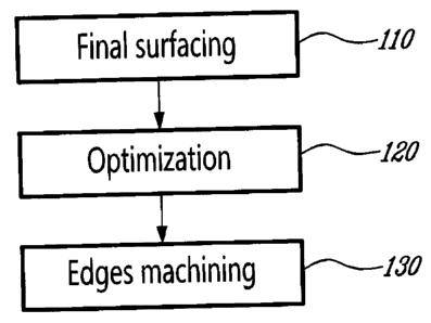
[0017] Figure 2
is a flowchart of a method according to an embodiment
of a first aspect of the present invention;
[0018] Figure 3
is a detailed flowchart of a method according to an
embodiment of the first aspect of the present invention ;
[0019] Figure 4
illustrates a first unit of an embodiment of a machine
according to a second aspect of the present invention; and
[0020] Figure 5
illustrates a second unit of an embodiment of a
machine according to the second aspect of the present invention.
DESCRIPTION OF ILLUSTRATIVE EMBODIMENTS
[0021] The
present invention is illustrated in further details by the following
non-limiting examples.
[0022]
According to an embodiment of a first aspect of the present
invention, a method is provided, as shown in the flowchart of Figures 2 and 3.
[0023] The
method generally comprises, for each raw lumber, surfacing
both faces to final dimension in a surfacing unit (Step 110); selecting the
best face
CA 02636544 2013-06-19
6
along the length of the surfaced lumber (Step 120); and edges machining in a
profiling unit (Step 130).
[0024] In step 110, raw lumbers are fed between presser rolls of a self-
centering finishing planer, as described for example in US patent 6,447,386,
which
may accommodate even badly wrapped raw lumbers or raw lumbers having local
deformations and allow feeding raw lumbers having different geometries. Both
top
and bottom faces of each raw lumber are surfaced simultaneously as knifes
positioned face to face perform a rough surfacing and then two other offset
knifes
do the finishing as will be discussed in relation to Figure 4 for example,
thereby
allowing achieving a precise finished thickness of the surfaced lumbers.
[0025] When both top and bottom faces are thus planed and the lumber has
its final thickness, the best available surface is selected in step 120 along
the
length of the lumber, so as to determine optimized lengths of best face on
each
face. For example, for a given lumber, a first length on the top face may be
selected as the best face, followed by a second length on the bottom face,
etc...
[0026] In a complete automated step 120, the final surfaced lumbers are
scanned, on at least the faces thereof, for detection of defects and grade
(step
111) and all defects and grade zones are cut on an automated chop saw (step
112). Alternatively, in a semi-automated step 120, defects and grade that are
manually marked by operators (step 113) are cut on an automated chop saw (step
112). Otherwise, in a manual step 120, defects and grade are manually cut out
from the final-surfaced lumbers obtained in step 110 and in step 114.
[0027] In any case, boards are then positioned on their best face and
best
end (step 116), and transferred to the profiling unit or side matcher.
[0028] In the complete automated step 120, no human intervention is
CA 02636544 2013-06-19
7
needed. In the semi-automated step 12, optimization is achieved by operators
and
the automated saw reads the marking done by the operators to cut our defects
and
grade. In the manual step 120, the whole step is performed by operators.
[0029] Since two finished faces are thus provided and the final thickness
of
the lumber obtained in a first step, it is possible to optimize the best
available
surfaces in step 120, since each lumber is already cut depending on variations
of
shades and coloration thereof, or according to physical defects, which allows
use
of maximized fine surfaces available on each face of the lumber. Each plank is
thus graded even before its edges are machined in step 130.
[0030] When the best available surfaces are optimized for each lumber,
the
lumber is then introduced in a profiling unit (step 130). The profiling unit
comprises
heads for precise machining of tenons and mortises, as well as chamfers if
needed. A further head provided with knives may be used to cut grooves on the
face opposite the working face as will be discussed hereinbelow in reference
to
Figure 5.
[0031] Therefore, the present method eliminates a step of pre-surfacing
the
lumbers by first cutting out major physical defects as is standardly done in
the art,
which allows reducing waste of material by preventing imprecise cutting or
wrong
decision by an operator, for example.
[0032] A machine according to an embodiment of another aspect of the
present invention will now be described in relation to Figures 4 and 5.
[0033] The machine generally comprises a first unit for surfacing both
faces
of the lumbers (finishing planer), and a second unit (or profiling unit) for
machining
the edges of the lumbers, and providing grooves if needed.
CA 02636544 2013-06-19
8
[0034] Figure 4 illustrates a first unit 40 for surfacing both faces,
using, for
example, a series of presser rolls 42 for pre-surfacing and a series of
presser rolls
44 for finishing both sides in a single machine. Offset rollers as shown in 44
are
found to achieve an efficient finishing.
[0035] Calibrating rollers preventing slippage of the lumbers, as
described
in US patent 6,447,386, and allowing surfacing both faces of the lumber while
accommodating possible bending and physical defects of the lumber, may be
used. Such rollers allow eliminating jamming events due to friction of the
lumbers,
as discussed in US patent 6,447,386, hence allowing a continuous production of
planks without interruptions.
[0036] Figure 5 illustrates a second unit 50 for machining the edges of
the
lumbers (in step 130), including for example rolls 52, 54 for conveying the
lumbers,
with a head provided with knives 56 for surface finishing both edges, and a
further
head 58 for machining grooves. Provision of two offset rows of rolls 52, 54 as
illustrated in Figure 5 allows conforming to the curvature of each lumber as
it
passes therethrough, for an optimized cut. Moreover, it allows processing
short
lumbers, of down to 8" for example, in a through feed fashion, without needing
to
have them pushed through the machine by longer ones so as to prevent them from
being stuck between the knives, as is currently the case in standard
installations.
[0037] The second unit 50 produces lumbers provided with tenons,
mortises, optionally chamfrains, and grooves on the face opposite the working
face
if needed. Quick adjustments are made in accordance to target widths.
[0038] Provision of two distinct units allows separation of the step of
final
surfacing the faces (110) from the step of machining the edges and grooves
(130),
and permits an increased flexibility. For example, since in a first step 110,
only the
faces of the lumbers are processed, the required adjustments are very quick
and
CA 02636544 2013-06-19
-
9
adjustments in case of variation of lumber widths may be achieved in less than
30
seconds, whereas similar adjustments required in currently available machines
may require between 5 and 15 minutes.
[0039] At the output of the first unit, the lumbers have two finished
surfaces,
which allows, in a step 120, a precise assessment of coloration variations and
detection of physical defects. As a result, lengths of the best one of the two
finished faces are accurately selected as lengths for the working face, and
cutting
out of defects is done precisely, without waste of material. Each lumber may
be
oriented to present the wane on the edge of the tenon. The assessment may be
done either by operators or by vision systems or by a combination thereof, and
different levels of automation may be contemplated, as shown in Figure 3.
[0040] As will be apparent to a person skilled in the art, the present
machine and method allow a drastically simplified process, resulting in the
operators being efficiently operational after a reduced time of training.
[0041] Moreover, problems of planks jamming are eliminated, and
increased precision is achieved, which may even result in reducing, even
eliminating, quality controls usually required at the output.
[0042] As people in the art will appreciate, such machine and method of
the
present application allow optimizing the yield of surfaced lumbers.
[0043] Although the present invention has been described hereinabove by
way of embodiments thereof, it may be modified, without departing from the
nature
and teachings of the subject invention as defined in the appended claims.