Note: Descriptions are shown in the official language in which they were submitted.
CA 02640245 2008-10-03
VAPOR HYDRATED CATHETER ASSEMBLY
AND METHOD OF MAKING SAME
FIELD OF THE DISCLOSURE
The present disclosure generally relates to catheter assemblies that are
delivered to
end users in a ready-to-use condition, and more particularly, to such a
catheter assembly
that is vapor hydrated and a method of making a vapor hydrated catheter
assembly.
BACKGROUND OF THE DISCLOSURE
It is generally well known that there are two distinct types of intermittent
urinary
catheters typically used by those who are able to do so without the assistance
of a
healthcare professional. These catheters include lubricated catheters which
utilize a gel
that is applied to the outer surface of the catheter tube prior to insertion
into the urethra
and hydrophilic catheters wherein a hydrophilic coating on the catheter tube
is activated
prior to use by treatment with a liquid such as water or saline solution. In
the case of
hydrophilic catheters, the liquid which is utilized to treat the hydrophilic
coating must be
provided by the manufacturer if the catheter is to be delivered to an end user
in a ready-to-
use condition.
As a result, it is necessary for the hydrophilic coating to either be
activated at a
point in time just prior to placing the catheter in a package or after placing
it in a package.
The more common approach is to place the hydrophilic coated catheter in a
package
together with the liquid. In particular, the liquid for activating the
hydrophilic coating on
the catheter has typically been placed loosely within the package or it has
been in a
container placed within the package.
With regard to placing the liquid loosely within the package, this has been
found to
be an undesirable approach because it presents a spill hazard. The loose
liquid is typically
provided in a reasonably significant quantity to ensure that there will be
sufficient liquid
remaining through a commercially viable shelf life to maintain the hydrophilic
coating in
an activated condition. However, since it is necessary to provide a reasonably
significant
quantity of the liquid to ensure there will be direct contact of the liquid
with the
hydrophilic coating following assembly, the liquid can easily spill from the
package when
the package is opened and may thereby wet and/or stain the end user's
clothing. In
1
CA 02640245 2008-10-03
addition, there is a serious technical problem which relates to the condition
in which such
a ready-to-use hydrophilic catheter must be sterilized.
Specifically, the sterilization process must take place after the catheter and
loose
liquid have been sealed within the package. Thus, the catheter is sterilized
when the
hydrophilic coating is wet, i.e., after it already has been activated by the
liquid. However,
a wet hydrophilic coating may degrade upon sterilization using conventional
techniques,
e.g., radiation. In particular, the wet hydrophilic coating may detach from
the catheter tube
resulting in a bumpy, high coefficient of friction surface.
To avoid such sterilization problems, some manufacturers place a liquid
container
within the package. According to this arrangement, the end user is provided
with
instructions to rupture or otherwise open the liquid container to permit the
liquid to be
released within the package so it can activate the hydrophilic coating. The
liquid can be
provided in a more limited quantity since the user can be instructed to
manipulate the
package for a period of time to ensure direct contact of the liquid with the
hydrophilic
coating immediately prior to use. The technical problem of degradation of a
wet
hydrophilic coating during sterilization is avoided because the liquid is
confined to the
liquid container during sterilization which means the hydrophilic coating is
in a dry state
at time of sterilization. However, there are still drawbacks because the
catheter is not in a
ready-to-use condition when it reaches the end user since the hydrophilic
coating requires
activation by rupturing/opening the liquid container and manipulating the
package.
There is the continuing presence of a spill hazard even though the liquid may
be
provided in a more limited quantity. The liquid will be contained loosely
within the
package interior space holding the catheter after the liquid container has
been ruptured to
release the liquid so it can easily spill on the end user when the package is
opened to
remove the catheter. In addition, the presence of the liquid can wet the hands
of the end
user making it more difficult and messy to handle the catheter.
As noted above, hydrophilic coated catheters typically are provided with a
thin
hydrophilic coating adhered to the outer surface of the catheter for
activation by direct
contact with a liquid. When the hydrophilic coating is activated by contact
with a
hydrating liquid such as water, it provides an extremely low coefficient of
friction surface.
Whether the hydrating liquid is brought into direct contact with the
hydrophilic coating by
2
CA 02640245 2008-10-03
the manufacturer or the end user, it is generally recognized that it takes
around 30 seconds
to activate the coating.
In all of these existing products, the catheter therefore depends upon direct
contact
of the liquid swelling medium (e.g., liquid water) with the entirety of the
hydrophilic
coated catheter surface for a period of time typically recognized as being 30
seconds.
Moreover, all of these existing products achieve direct liquid water contact
by providing a
package for the catheter that permits liquid water to flow freely within the
catheter-
containing cavity of the package, and permits unobstructed access of the
liquid water to
the catheter surface for direct contact therewith. Because of the free flow of
loose liquid
water within the package and unobstructed access to the catheter surface, it
is easy to
ensure direct contact of the liquid swelling medium with the entire surface of
the catheter
that has been treated with the hydrophilic coating.
However, it has remained a technical challenge to provide a urinary catheter
which
has a hydrophilic coating where the catheter meets all of the important
criteria for such a
product from the perspective of both the manufacturer and the end user,
including the
ability to sterilize the catheter without degrading the hydrophilic coating
due to wetting
prior to sterilization or exposing the end user to a spillage hazard from the
liquid water
which has been placed in direct contact with the hydrophilic coating.
SUMMARY OF THE DISCLOSURE
Accordingly, the present disclosure is generally directed to a catheter
assembly
comprising a catheter having a hydrophilic coating on at least a part of its
length intended
to produce a low-friction surface on the catheter when treated with a
hydrating substance.
The catheter assembly also includes a catheter package forming an interior
space divided
by a gas permeable, liquid impermeable barrier into first and second distinct
and separate
cavities. The first cavity accommodates the catheter therein and the second
cavity
accommodates at least liquid phase water or an aqueous liquid therein. In this
regard, the
liquid phase water or aqueous liquid therein is capable of changing phase
inside the
second cavity from a liquid to a vapor which is then available to activate the
hydrophilic
coating on the catheter.
In its liquid phase, the water or aqueous liquid is confined to the second
cavity
because of the gas permeable, liquid impermeable barrier dividing the interior
space into
3
CA 02640245 2008-10-03
the two cavities is liquid impermeable. Thus, if the liquid water or aqueous
liquid did not
undergo a phase change from a liquid to a vapor within the second cavity, the
hydrophilic
coating on the catheter would not be hydrated. However, after the liquid water
or aqueous
liquid undergoes a phase change from a liquid to a vapor, the vapor in the
second cavity is
capable of passing from the second cavity, through the gas permeable, liquid
impermeable
barrier, into the first cavity.
In the first cavity, the vapor serves as the hydrating substance for the
hydrophilic
coating, and the vapor is capable of reaching the first cavity because the gas
permeable,
liquid impermeable barrier dividing the package interior space into two
distinct and
separate cavities is gas permeable. Therefore, after a phase change, the
hydrophilic coating
on the catheter will be hydrated by the vapor resulting from the phase change.
In other
words, the vapor generated by the phase change of the liquid in the second
cavity is
capable of passing from the second cavity, through the gas permeable, liquid
impermeable
barrier, into the first cavity to cause the hydrophilic coating on the
catheter to be hydrated.
By this arrangement, it is possible to produce the low-friction surface on the
catheter so it is in a fully ready-to-use condition when the catheter reaches
the end user.
As will be appreciated, the liquid in the second cavity remains a liquid until
some
or all of it undergoes a phase change to become a vapor. To the extent the
liquid changes
phase in the second cavity, it will be understood that there will be less
liquid remaining in
the second cavity, but at no time does liquid ever pass directly from the
second cavity into
the first cavity because of the gas permeable, liquid impermeable barrier.
Accordingly,
liquid contained in the second cavity can never directly contact the
hydrophilic coating,
and it can never directly hydrate the hydrophilic coating; only vapor
resulting from a
phase change can do that.
While the vapor which passes from the second cavity, through the gas
permeable,
liquid impermeable barrier, into the first cavity may undergo some
condensation within
the first cavity, liquid droplets in the first cavity resulting from such
condensation will
comprise a de minimis amount of liquid far less than would be required to
produce liquid
hydration of the hydrophilic coating on the catheter.
Preferably, the catheter package forming the interior space is made of a
single gas
impermeable rectangular sheet, with opposite edges joined by a single
longitudinal seal
and having an end seal at each of opposite ends thereof. It may alternatively
be formed of
4
CA 02640245 2008-10-03
a gas impermeable material comprised of two confronting rectangular sheets
joined by a
seal extending entirely about the perimeters of the sheets. Further, the
catheter assembly
advantageously includes a wicking material within the second cavity. A
rupturable
container may be provided for selective liquid flow communication with the
wicking
material.
In one exemplary embodiment, a rupturable container may be provided within the
catheter package for selective liquid flow communication with the second
cavity in spaced
relation to the wicking material. In another exemplary embodiment, the
rupturable
container may include a rupturable compartment within the catheter package in
spaced
relation to the wicking material for selective liquid flow communication with
the wicking
material through a rupturable seal.
From the foregoing, it will be appreciated that the hydrating substance for
activating the hydrophilic coating on the urinary catheter comprises water
vapor, or vapor
phase water. The vapor which is used to activate the hydrophilic coating
results from a
phase change of water from liquid water to water vapor in the second cavity of
the catheter
package space.
In another respect, the present disclosure is directed to a method of making a
ready-to-use catheter assembly comprising the step of providing a catheter
package having
an interior space divided by a gas permeable, liquid impermeable barrier into
a first cavity
and a second cavity. The method also includes the steps of placing a catheter
having a
hydrophilic coating on at least a part of its length into the first cavity and
placing liquid
into the catheter package so as to be in liquid isolation relative to the
first cavity. Still
additionally, the method further includes the step of placing the liquid
directly into, or for
selective liquid flow communication with, the second cavity of the catheter
package and
also includes the step of sealing the catheter package such that the catheter
is disposed
within the first cavity.
In addition, in accordance with another aspect of the disclosure, the method
may
include the step of delaying distribution or use of the catheter assembly for
a period of
time sufficient for one or more of several things to occur. In particular,
distribution or use
may be delayed for a time sufficient for (i) the liquid to be placed either
directly into, or in
selective liquid flow communication with, the second cavity, (ii) at least
some of the liquid
to change phase to vapor within the second cavity, (iii) at least some of the
vapor to pass
CA 02640245 2008-10-03
from the second cavity, through the gas permeable, liquid impermeable barrier,
and into
the first cavity, and/or (iv) the vapor in the first cavity to hydrate the
hydrophilic coating to
produce a low-friction surface on the catheter, whereby the catheter assembly
is ready-to-
use. Furthermore, the method may advantageously include the step of providing
the liquid
in a rupturable container.
More specifically, the liquid may be provided in a rupturable container which
is in
communication with the second cavity. The method then may advantageously
include the
step of providing a wicking material within the second cavity in order to
absorb the liquid
after the rupturable container has been breached. In this manner, the wicking
material can
absorb and distribute the liquid so at least a portion of it can thereafter
undergo a phase
change to change to vapor within the second cavity. The vapor migrates through
the vapor
permeable, liquid impermeable barrier into the first cavity where it hydrates
the
hydrophilic coating on the catheter.
As will be appreciated, liquid is always confined to the second cavity because
the
barrier dividing the interior space of the catheter package into first and
second cavities is
liquid impermeable. Accordingly, the hydrophilic coating on the catheter in
the first cavity
cannot be hydrated until at least a portion of the liquid undergoes a phase
change to
change to vapor. However, once there is vapor present in the second cavity as
a result of
the phase change, vapor can pass through the barrier into the first cavity to
hydrate the
hydrophilic coating because the barrier is gas permeable.
One exemplary method includes the steps of forming the catheter package to
have
a generally elongated rectangular shape and providing the liquid in a
rupturable container
within the second cavity in spaced relation to one end of the catheter. The
method may
then advantageously include the step of placing a wicking material in the
second cavity to
extend longitudinally generally coextensive with the catheter in the first
cavity and the
wicking material having an end thereof positioned in proximity to the
rupturable container.
The method may then also advantageously include the step of providing a seal
extending
inwardly from each side of the catheter package between the catheter and the
rupturable
container to form a passageway for the liquid to pass to the end of the
wicking material.
Another exemplary method includes the steps of forming the catheter package to
have a generally elongated rectangular shape and providing the liquid in a
rupturable
compartment of the catheter package for selective liquid flow communication
with the
6
CA 02640245 2008-10-03
second cavity. The method may then advantageously include the steps of forming
the
rupturable compartment by providing a rupturable seal and placing a wicking
material in
the second cavity so as to be longitudinally generally coextensive with the
catheter in the
first cavity. The method may then also advantageously include the wicking
material being
positioned in the second cavity for selective liquid flow communication with
the
rupturable compartment after the rupturable seal is breached and the wicking
material
having an end in proximity to the rupturable seal.
In the last-mentioned exemplary method, it may further advantageously include
the
step of forming an intermediate seal across the catheter package between the
rupturable
seal and the catheter so as to extend across the wicking material to form an
intermediate
compartment to thereby define a liquid-receiving space.
In both of these exemplary methods, the catheter and the liquid are sterilized
after
the catheter package has been sealed but before the liquid has been released
for absorption
by the wicking material. Another feature of the exemplary methods is to sever
the catheter
package between the catheter and the rupturable container for the liquid after
releasing the
liquid. Still another feature of the exemplary methods is to thereafter form
an end seal for
the catheter package so that it is fully sealed for shipment to an end-user in
a ready-to-use
condition.
A further exemplary method includes the steps of forming the catheter package
to
have a generally elongated rectangular shape and placing the liquid directly
into the
second cavity in liquid isolation relative to the catheter. The method may
then
advantageously include the step of placing a wicking material in the second
cavity to
extend longitudinally generally coextensive with the catheter in the first
cavity. The
method may then also advantageously include the step of providing a gas
permeable,
liquid impermeable barrier within the package interior space to define the
first and second
cavities and to maintain the liquid out of direct contact with the hydrophilic
coated
catheter.
In this exemplary method, the catheter and the liquid are sterilized after the
catheter package has been sealed. This can be done at the end of the assembly
line shortly
after the catheter package has been sealed and little or no liquid has
vaporized or, by
selecting a material for the gas permeable, liquid impermeable barrier having
a relatively
low gas permeability, sterilization can be done within a few days thereafter.
Since, at the
7
CA 02640245 2012-04-03
time of sterilization, the hydrophilic coating will not have been
substantially hydrated by
vapor in either instance, the sterilization will not cause the coating to
degrade.
Other objects, advantages, and features of the present disclosure will become
apparent from a consideration of the following specification taken in
conjunction with the
accompanying drawings.
In one aspect, there is provided a catheter assembly comprising a catheter
having a
hydrophilic coating on at least a part of its length intended to produce a low-
friction
surface on the catheter when treated with a hydrating substance, a catheter
package formed
of a gas impermeable sheet material defining an interior space, a gas
permeable, liquid
impermeable mid-package film or membrane secured to the sheet material forming
the
catheter package, the mid-package film or membrane cooperating with the sheet
material
to physically divide the interior space in the catheter package into first and
second cavities,
the first cavity accommodating the catheter and the second cavity
accommodating a
wicking material and a quantity of liquid, the wicking material being disposed
within the
second cavity for liquid flow communication with a rupturable container for
the liquid to
absorb the liquid when the container has been breached, the liquid absorbed by
the
wicking material being capable of changing phase into vapor capable of passing
from the
second cavity, through the gas permeable, liquid impermeable mid-package film
or
membrane, and into the first cavity, the vapor passing into the first cavity
serving as the
hydrating substance for treatment of the hydrophilic coating to produce the
low-friction
surface on the catheter.
In another aspect, there is provided a catheter assembly comprising a catheter
having a hydrophilic coating on at least a part of its length intended to
produce a low-
friction surface on the catheter when treated with a hydrating substance, a
catheter
package formed of a gas impermeable sheet material defining an interior space,
a gas
permeable, liquid impermeable mid-package film or membrane secured to the
sheet
material forming the catheter package, the mid-package film or membrane
cooperating
with the sheet material to physically divide the interior space in the
catheter package into
first and second cavities, the first cavity accommodating the catheter and the
second cavity
accommodating a wicking material and a quantity of liquid, the wicking
material being
disposed within the second cavity for liquid flow communication with a
rupturable
compartment for the liquid to absorb the liquid when a rupturable seal has
been breached,
8
CA 02640245 2012-04-03
the liquid absorbed by the wicking material being capable of changing phase
into vapor
capable of passing from the second cavity, through the gas permeable, liquid
impermeable
mid-package film or membrane, and into the first cavity, the vapor passing
into the first
cavity serving as the hydrating substance for treatment of the hydrophilic
coating to
produce the low-friction surface on the catheter.
In another aspect, there is provided a method of making a ready-to-use
catheter
assembly, comprising the steps of providing a catheter package having an
interior space
and providing a gas permeable, liquid impermeable mid-package film or membrane
secured to and cooperating with the catheter package to physically divide the
catheter
package into a first cavity and a second cavity, placing a catheter having a
hydrophilic
coating on at least a part of its length, a wicking material, and a quantity
of liquid into the
catheter package, sealing the catheter package with at least the part of the
catheter having
the coating within the first cavity, the wicking material in the second
cavity, and the liquid
with the catheter package in a manner making it possible for the liquid to be
absorbed by
the wicking material, and delaying distribution of the catheter assembly for a
period of
time sufficient for i) the liquid to be absorbed by the wicking material, ii)
at least some of
the liquid to change phase into vapor in the second cavity, iii) at least some
of the vapor to
pass from the second cavity, through the gas permeable, liquid impermeable
barrier, and
into the first cavity, and iv) the vapor in the first cavity to hydrate the
hydrophilic coating
to produce a low-friction surface on the catheter, whereby the catheter
assembly is ready-
to-use.
In another aspect, there is provided a method of making a ready-to-use
catheter
assembly, comprising the steps of providing a catheter packing having an
interior space
and providing a gas permeable, liquid impermeable mid-package film or membrane
secured to and cooperating with the catheter package to physically divide the
catheter
package into a first cavity and a second cavity, placing a catheter having a
hydrophilic
coating on at least a part of its length, a wicking material, and a quantity
of liquid into the
catheter package, the quantity of liquid being disposed within a rupturable
container or a
rupturable compartment formed in the catheter package by a rupturable seal for
liquid flow
communication with the second cavity, sealing the catheter package with at
least the part
of the catheter having the coating in the first cavity, the wicking material
in the second
cavity, and the liquid in the rupturable container or the rupturable
compartment, breaching
8a
CA 02640245 2012-04-03
the rupturable container or the rupturable seal of the rupturable compartment
after sealing
the catheter package to release the liquid for absorption by the wicking
material, and
delaying distribution of the catheter assembly for a period of time sufficient
for i) the
liquid to be absorbed by the wicking material, ii) at least some of the liquid
to change
phase into vapor in the second cavity, iii) at least some of the vapor to pass
from the
second cavity, through the gas permeable, liquid impermeable barrier, and into
the first
cavity, and iv) the vapor in the first cavity to hydrate the hydrophilic
coating to produce a
low-friction surface on the catheter, whereby the catheter assembly is ready-
to-use.
BRIEF DESCRIPTION OF THE DRAWINGS
Figure 1 is a diagrammatic plan view of a vapor hydrated catheter assembly,
including a catheter package, constructed in accordance with the present
disclosure;
Figure 2 is a diagrammatic cross-sectional view of the catheter assembly of
Figure 1 taken generally along the lines 2-2 thereof,
Figure 2A is a diagrammatic cross-sectional view similar to Figure 2 but
showing
an alternative form for the catheter package;
Figure 3 is a diagrammatic cross-sectional view of the catheter assembly of
Figure 1 taken generally along the lines 3-3 thereof,
Figure 3A is a diagrammatic cross-sectional view similar to Figure 3 but
showing
an alternative form for the catheter package;
Figure 4 is a diagrammatic plan view of the catheter assembly of Figure 1
showing
one step in the method disclosed herein;
Figure 5 is a diagrammatic plan view of the catheter assembly of Figure 1
showing
another step in the method disclosed herein;
Figure 6 is a diagrammatic plan view of the catheter assembly of Figure 1
showing
another step in the method disclosed herein;
Figure 7 is a diagrammatic plan view of an alternative embodiment of a vapor
hydrated catheter assembly;
Figure 8 is a diagrammatic plan view of the catheter assembly of Figure 7
showing
one step in the method disclosed herein;
Figure 9 is a diagrammatic plan view of the catheter assembly of Figure 7
showing
another step in the method disclosed herein;
8b
CA 02640245 2012-04-03
Figure 10 is a diagrammatic plan view of the catheter assembly of Figure 7
showing another step in the method disclosed herein;
8c
CA 02640245 2008-10-03
Figure 11 is a diagrammatic cross-sectional view of the catheter assembly of
Figure 7 taken generally along the lines 11-11 thereof;
Figure 11 A is a diagrammatic cross-sectional view similar to Figure 11 but
showing an alternative form of liquid barrier in the catheter package;
Figure 12 is a diagrammatic plan view of another alternative embodiment of a
vapor hydrated catheter assembly;
Figure 12A is a diagrammatic cross-sectional view of the catheter assembly of
Figure 12 taken generally along the line 12A-12A thereof;
Figure 12B is an enlarged diagrammatic detail view of the portion of Figure 12
indicated by a dot-dash circle in Figure 12, showing the positioning of the
heat seal and
tear tape;
Figure 13 is a diagrammatic plan view of still another alternative embodiment
of a
vapor hydrated catheter assembly;
Figure 14 is a diagrammatic plan view of still another alternative embodiment
of a
vapor hydrated catheter assembly; and
Figure 14A is a diagrammatic cross-sectional view of the catheter assembly of
Figure 14 taken generally along the line 14A-14A thereof.
DETAILED DESCRIPTION
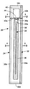
In the illustrations given herein, and with reference first to Figure 1, the
reference
numeral 20 designates generally a vapor hydrated catheter assembly in
accordance with
one aspect of the disclosure. The catheter assembly 20 comprises a urinary
catheter
generally designated 22 which has a hydrophilic coating on at least a part of
its length
intended to produce a low-friction surface on the catheter 22 when treated
with a hydrating
substance. The catheter assembly 20 also includes a catheter package generally
designated
24 which forms an interior space 26 (see, also, Figure 3) divided by a gas
permeable,
liquid impermeable barrier 28 into a first cavity 26a and a second cavity 26b.
The first
cavity 26a accommodates the catheter 22 therein and the second cavity 26b
accommodates
at least a quantity of vapor donating liquid 30 in its liquid phase such as,
e.g., liquid phase
water therein. The quantity of liquid phase water 30 may contain, for example,
pure liquid
water, or any suitable aqueous solution. In this regard, the quantity of
liquid 30 in its liquid
phase is considered to be "vapor donating" because liquid is capable of
changing phase
9
CA 02640245 2008-10-03
inside the second cavity 26b from a liquid to a vapor that can serve as an
activating or a
hydrating substance. As will be appreciated from Figure 1, the catheter
package 24 is of a
generally elongated rectangular shape and includes a rupturable container 40
containing
the liquid 30 for selective liquid flow communication with the second cavity
26b.
The liquid 30 is confined within the second cavity 26b because of the liquid
impermeable nature of the gas permeable, liquid impermeable barrier 28 which
may be
configured as a mid-package film or membrane. This film or membrane physically
divides
the interior space 26 into the two cavities 26a and 26b such that the
hydrophilic coating
cannot be activated or hydrated until at least a portion of the quantity of
vapor donating
liquid 30 in its liquid phase undergoes a phase change from a liquid to a
vapor. However,
after the liquid 30 does undergo a phase change from a liquid to a vapor, the
vapor in the
second cavity 26b is then capable of passing from the second cavity 26b,
through the gas
permeable, liquid impermeable barrier 28, and into the first cavity 26a to
serve as the
activating or hydrating substance.
In the embodiment illustrated in Figures 1 through 3, the catheter package 24
forming the interior space 26 is comprised of two confronting rectangular
sheets 24a
and 24b of gas impermeable material joined by a seal 32 extending entirely
about the
perimeters of the sheets 24a and 24b. Alternatively, as will be appreciated
from
Figures 2A and 3A, a catheter package 24' may be formed of a single
rectangular sheet of
material wrapped about the catheter 22' and the liquid 30' so as to
encapsulate them with
opposite edges 24a' and 24b' joined by a single longitudinal seal as at 34'
and end seals at
each of opposite ends thereof. Thus, the only difference between the
embodiments shown
in Figures 2, 3 and Figures 2A, 3A is that the latter embodiment has a single
longitudinal
seal as at 34' because it is formed of a single sheet of material whereas the
former
embodiment has a pair of longitudinal side seals as at 32a and 32b because it
is formed of
two sheets of material.
As will be appreciated from the foregoing description, both of the embodiments
shown in Figures 2 and 2A have end seals such as the end seals 32c and 32d
(see Figure 1)
which are provided at each of the opposite ends of the respective packages 24
and 24'.
Referring to Figures 1, 3, and 3A, it will be seen that the catheter
assemblies 20,
20' include a wicking material 36, 36' within the second cavities 26b, 26b' of
the interior
spaces 26, 26' for selective liquid flow communication with the rupturable
container 40
CA 02640245 2008-10-03
for the liquid 30, 30', to absorb the liquid 30, 30' when the rupturable
container 40 is
breached. It will again be appreciated that the only difference between the
embodiments
shown in Figures 3 and 3A is the difference in the catheter packages 24 and
24' as
described in detail above. In other words, Figures 3 and 3A illustrate,
respectively, the
wicking material 36 within the second cavity 26b in a catheter package 24
formed of two
sheets of material (Figure 3) and the wicking material 36' within the second
cavity 26b' in
a catheter package 24' formed of a single sheet of material (Figure 3A).
The wicking material 36 within the second cavity 26b extends longitudinally so
as
to be generally coextensive with the catheter 22 in the first cavity 26a. An
end 36a of the
wicking material 36 is preferably positioned in spaced relation but in
proximity to the
rupturable container 40. The catheter package 24 includes seals 42a and 42b
extending
inwardly from each side of the package between the catheter 22 and the
rupturable
container 40 to form a passageway as at 44 for the liquid 30 to pass from the
rupturable
container 40, after it has ruptured, to the end 36a of the wicking material
36.
While not specifically shown, it will be appreciated that the structural
features as
well as the details of construction of the catheter assembly 20' in the
embodiment of
Figures 2A and 3A are designated by a "prime" symbol and are essentially
identical to
those described above in connection with the catheter assembly 20, except
where noted
otherwise.
Referring now to Figures 7 through 11, an alternative embodiment of a catheter
assembly 120 is illustrated which includes a catheter generally designated 122
having a
hydrophilic coating on at least a part of its length intended to produce a low-
friction
surface on the catheter 122 when treated with a hydrating substance. The
catheter
assembly 120 also includes a catheter package generally designated 124 which
is formed
of a gas impermeable material to have an interior space 126 divided by a gas
permeable,
liquid impermeable barrier 128 into first and second cavities 126a and 126b.
The first
cavity 126a accommodates the catheter 122 therein and the second cavity 126b
accommodates a wicking material 136 for communication with a liquid 130.
The liquid 130 is within a rupturable compartment 146 within the catheter
package 124 in spaced relation to the wicking material 136 for selective
liquid flow
communication with the wicking material 136 through a rupturable seal 148. The
wicking
material 136 is within the second cavity 126b of the interior space 126 for
selective liquid
11
CA 02640245 2008-10-03
flow communication with the rupturable compartment 146 within the catheter
package 124
containing the liquid 130 after the rupturable seal 148 is breached. The
liquid 130
absorbed by the wicking material 136 is capable of undergoing a phase change
from a
liquid to a vapor. After the liquid 130 undergoes a phase change, the vapor
resulting from
the phase change passes from the second cavity 126b, through the gas
permeable, liquid
impermeable barrier 128, and into the first cavity 126a to hydrate the
hydrophilic coating
to produce the low-friction surface on the catheter 122.
As with the embodiment illustrated in Figures 1 and 2, the catheter package
124 is
of a generally elongated rectangular shape, but has a rupturable compartment
146
containing the liquid 30 rather than a rupturable container such as 40 in
Figure 1. The
rupturable compartment 146 is disposed for selective liquid flow communication
with the
second cavity 126b.
With regard to the respective embodiments of Figures 1 and 2 and Figures 7
and 11, the packages 24 and 124 are comprised of two confronting rectangular
sheets 24a,
24b and 124a, 124b, respectively, which overlie one another and are joined
together by
seals 32 and 132, respectively, which include longitudinal side seals 32a, 32b
and 132a,
132b, respectively, as well as end seals 32c, 32d and 132c, 132d,
respectively. The gas
permeable, liquid impermeable barriers 28 and 128 serve to divide the interior
spaces 26
and 126, respectively, into first cavities 26a, 126a, respectively, and second
cavities 26b,
126b, respectively, as shown.
However, the gas permeable, liquid impermeable barrier 128 in the embodiment
of
Figures 7 and 11 is formed quite differently from the gas permeable, liquid
impermeable
barrier 28 in the embodiment of Figures 1 and 2 in that the former comprises a
gas
permeable, liquid impermeable sleeve, rather than a mid-package film or
membrane,
which holds and confines the wicking material 136 so as to be maintained in
liquid
isolation from the catheter 122 within the interior space 126 of the package
124.
Referring to Figure 11 A, it is possible as an alternative to utilize a gas
permeable,
liquid impermeable barrier 128' formed in a substantially similar manner to
the gas
permeable, liquid impermeable barrier 28 in Figures 1 and 2 such that the gas
permeable,
liquid impermeable barrier 128' will extend entirely through the interior
space 126' and be
captured by the longitudinal side seals such as 132a', 132b' and at least one
of the end
seals such as 132d so as to be sealed with the confronting rectangular sheets
124a', 124b'.
12
CA 02640245 2008-10-03
When this alternative embodiment is utilized, the gas permeable, liquid
impermeable barrier 128' will be seen to comprise a mid-package film or
membrane
which cooperates with the rectangular sheets 124a', 124b' and the various
seals to divide
the interior space 126' into a first cavity 126a' and a second cavity 126b'
such that the
catheter 122' is accommodated in the first cavity 126a' of the interior space
126' and the
wicking material 136' is disposed within the second cavity 126b'. As before,
the liquid
130 is in a separate compartment such as the rupturable compartment 146 which
is in
liquid flow communication with the second cavity 126b' and, thus, with the
wicking
material 136' when the rupturable seal 148 is breached so that the liquid 130
can reach the
end 136a of the wicking material 136' (as seen in Figures 7 through 10) to be
wicked or
drawn therein.
In both of the embodiments which are illustrated in Figures 11 and 11 A, the
wicking material 136 and 136' within the respective second cavities 126b and
126b'
extend longitudinally generally coextensive with the respective catheters 122
and 122' so
as to have an end such as 136a thereof which is positioned in spaced relation,
but in
proximity to, the rupturable compartment 146 containing the liquid 130.
Furthermore, in
both of the embodiments which are illustrated in Figures 11 and 11 A, there is
a rupturable
seal 148 (see Figures 7 through 9) defining one boundary of the rupturable
compartment
146 for the liquid 130, and there is also an intermediate seal 150 disposed
between the
rupturable seal 148 and the respective catheters 122 and 122' extending across
the
respective wicking materials 136 and 136' to define an intermediate
compartment such
as 152.
With regard to the embodiment illustrated in Figure 11A, the intermediate seal
150
will be understood to capture the end of the gas permeable, liquid impermeable
barrier
128' opposite the end thereof which is captured by the end seal 132d. In other
words, it
will be understood that the gas permeable, liquid impermeable barrier 128' in
Figure I IA
is captured entirely about its perimeter by the respective side seals 132a'
and 132b' 124'
as well as an end seal 132d and the intermediate seal 150 (Figure 7). As a
result, it will be
appreciated that only the end portion 136a of the wicking material 136' will
extend
outwardly of the interior space 126' so as to be in the intermediate
compartment 152
(Figure 7).
13
CA 02640245 2008-10-03
When a single sheet of material is used to form a package such as 24' in
Figures 2A and 3A, the edges of the gas permeable, liquid impermeable barrier
28' will
not be captured by opposed side seals such as those shown in Figures 2 and 3.
Instead,
opposite side edges 28a' and 28b' of the gas permeable, liquid impermeable
barrier such
as 28' will be secured to the inner surface of the package 24'. While not
specifically
shown, it will be appreciated that the embodiment shown in Figure 11A can also
be
constructed of a single sheet of material to form the package 124' in
substantially the same
manner.
As shown in Figures 7 and 11, the catheter package 120 is formed such that the
intermediate compartment 152 is between the first and second cavities 126a and
126b
which accommodate the catheter 122 and the wicking material 136, on the one
hand, and
the rupturable compartment 146 which is provided for the liquid 130, on the
other hand,
for a reason which will be appreciated from the description of the disclosed
method below.
The intermediate compartment 152 will be seen to extend between the wicking
material
136 and the rupturable seal 148 of the rupturable compartment 146 to define a
liquid-
receiving space after the rupturable seal 148 has been breached to release the
liquid 130.
Furthermore, and as will be appreciated by referring to Figures 8 and 11, the
wicking
material 136 will be seen to have the end portion 136a which extends from the
second
cavity 126b through the intermediate seal 150 and into the intermediate
compartment 152
whereby it is able to wick and absorb the liquid 130 from the intermediate
compartment
152 into the second cavity 126b.
Still referring to Figures 7 and 11, the intermediate seal 150 cooperates with
the
sleeve-like gas permeable, liquid impermeable barrier 128 so as to confine
liquid drawn
into the wicking material 136 to the second cavity 126b and thereby keep
liquid from
entering the first cavity 126a. While not essential to the present disclosure,
the catheter
122 shown in Figure 7 can also be provided with a "no-touch" gas permeable,
liquid
impermeable sleeve 122a through which vapor in the first cavity 126a can pass
in order to
hydrate the hydrophilic coating on the catheter 122. The "no-touch" gas
permeable, liquid
impermeable sleeve 122a permits the end user to manipulate the catheter 122
without
touching the surface of the catheter 122. This feature reduces contamination
risk and
makes the catheter 122 easier to handle for the end user. The "no touch"
sleeve can be a
complete barrier to microorganisms, including viruses, thus providing
significant
14
CA 02640245 2008-10-03
protection for the user. This is possible only if the "no touch" sleeve is
made of a material
that is liquid impermeable, such as a monolithic polymer film.
The sleeve 122a may advantageously cover the entire hydrophilic coated portion
of
the catheter to make it possible for the end user to avoid making contact with
the portion
of the catheter which is intended to be inserted into the urethra to thereby
prevent or limit
the possibility of urinary tract infections.
In contrast to the embodiment illustrated in Figures 7 and 11, the wicking
material
136' in Figure I IA can be loosely positioned within the second cavity 126b'.
However, it
will be appreciated that in the Figure I IA embodiment there will also be an
intermediate
seal such as 150 in Figure 7. In this case, the intermediate seal 150 will
cooperate directly
with the wicking material 136' and the gas permeable, liquid impermeable
barrier 128' to
confine liquid drawn into the wicking material to the second cavity 126b'.
More specifically, the resulting product will resemble Figure 7 with the
sleeve-like
gas permeable, liquid impermeable barrier 128 removed and the mid-package film
or
membrane gas permeable, liquid impermeable barrier 128' taking its place to
physically
separate the catheter 122' and the wicking material 136' into the first and
second cavities
126a' and 126 b' shown in Figure 11A. Considering Figures 7 and 11A together,
it will be
appreciated that this is accomplished by having the side seals 132a' and
132b', an end seal
such as 132d and an intermediate seal such as 150 cooperate with the
rectangular sheets
124a', 124b' and the gas permeable, liquid impermeable barrier 128' to form
the first and
second cavities 126a' and 126b'. Further, it will also be appreciated that the
wicking
material 136' will have an end 136a thereof extend beyond the intermediate
seal 150 into
an intermediate compartment 152 where it can wick and absorb the liquid 130.
In all of the foregoing embodiments, both the catheter 22, 22', 122, 122' and
the
wicking material 36, 36', 136, 136' are disposed in a catheter package 24,
24', 124, 124'
of a generally elongated rectangular shape. The catheter 22, 22', 122, 122'
and at least a
major portion of the wicking material 36, 36', 136, 136' are also disposed
between seals
42a and 42b, or between intermediate seal 150 and the end seal 32d or 132d.
The
foregoing features will be appreciated by referring to Figures 1, 3, 3A, 7,
11, 11A, and the
reason they are located as described will be appreciated from the description
of the
disclosed method.
CA 02640245 2008-10-03
Before describing the method, it will also be noted in all embodiments that
each of
the respective catheter packages 24, 24', 124, 124' has a tear tape 56, 56',
156, 156' which
may be adhesively affixed to the inner surface of the sheet material forming
the catheter
package 24, 24', 124, 124'. The tear tape 56, 56', 156, 156' is affixed such
that it is
positioned along one side edge of the catheter package 24, 24', 124, 124'
within the first
sealed cavity 26a, 26a', 126a, 126a'. In addition, each of the respective
catheter packages
24, 24', 124, 124' may include a v-notch such as 58 (Figure 6) and 158 (Figure
10) which
extends a short distance into the end seal 54, 154 to facilitate opening the
package by
causing it to tear along the tear tape 56, 56', 156, 156'.
When the end user opens the package by using the tear tape 56, 56', 156, 156',
the
tear tape 56, 56', 156, 156' will be understood to cause the catheter package
24, 24', 124,
124' to tear along it to thereby cause the catheter package 24, 24', 124, 124'
to open along
an intended opening line for access to the catheter 22, 22', 122, 122' in the
first sealed
cavity 26a, 26a', 126a, 126a' without opening the second sealed cavity 26b,
26b', 126b,
126b'. The tear tape 56, 56', 156, 156' thus extends within the first sealed
cavity 26a,
26a', 126a, 126a' in a desired direction relative to the catheter 22, 22',
122, 122' to cause
the package 24, 24', 124, 124' to open along the intended opening line in a
manner
facilitating removal of the catheter from the package for use without opening
the second
sealed cavity 26b, 26b', 126b, 126b'. Thus, residual liquid still present in
the second
cavity 26b, 26b', 126b, 126b' that has not changed phase into vapor is safely
confined to
the second cavity 26b, 26b', 126b, 126b' and cannot spill on the end user. The
tear tape
56, 56', 156, 156' can advantageously be adhesively or otherwise affixed to an
inner
surface of the catheter package 24, 24', 124, 124' within the first sealed
cavity 26a, 26a',
126a, 126a' so as to extend generally from one end of the catheter package to
the other
end thereof in a manner whereby it will be generally parallel to the catheter
22, 22', 122,
122'.
When the end user opens the catheter package 24, 24', 124, 124', less of the
original liquid 30, 130 will be present in the second cavity 26b, 26b', 126b,
126b' as
compared to the time of manufacture, because some of it will have changed
phase to a
vapor. However, for the liquid 30, 130 which does remain, it is safely
confined in the
second cavity 26b, 26b', 126b, 126b'. By taking advantage of vapor hydration
of the
hydrophilic coating and isolating the liquid 30, 130 in a cavity that remains
sealed even
16
CA 02640245 2008-10-03
after removing the catheter 22, 22', 122, 122' from the catheter package 24,
24', 124,
124', there is no possibility of spillage.
While the vapor which passes from the second cavity 26b, 26b', 126b, 126b',
through the gas permeable, liquid impermeable barrier 28, 28', 128, 128', into
the first
cavity 26a, 26a', 126a, 126a' may undergo some observable condensation within
the first
cavity, the liquid droplets which may be found in the first cavity resulting
from such
condensation will comprise, at most, a de minimis amount of liquid which will
be far less
than what would be required to produce liquid hydration of the hydrophilic
coating on the
catheter 22, 22', 122, 122' and far less than what could possibly cause a
spillage hazard.
Some of this condensation may occur at a water activity below unity, due to
the presence
of surfaces and small spaces within the package, and may not be
thermodynamically
driven to enter the hydrophilic coating. In any event, the small liquid water
droplets
formed by condensation will not be capable of fully hydrating the coating and
making the
product ready to use by the conventional fast liquid activation.
It is possible to control the time for completing the hydration of the
hydrophilic
coating by selecting the degree of vapor permeability of the gas permeable,
liquid
impermeable barrier and, if used, the degree of vapor permeability of the "no-
touch"
catheter sleeve.
As also previously mentioned, the hydrating substance for activating the
hydrophilic coating on the urinary catheter comprises water vapor (vapor phase
water).
The water vapor which is used to activate the hydrophilic coating is at least
in part from
water that previously had been liquid water resident in the second cavity.
Thus, some of
the quantity of water placed within the catheter package in its liquid phase
may change
phase to vapor and thus continuously replace water vapor lost from the gas
phase as it
enters and activates the hydrophilic coating.
Example: A hydrophilic coating based on cross-linked polyvinylpyrollidone
was created on the surface of a PVC tube. A CaCO3 filled polyethylene film
(#728 from
RKW, Belgium) was used as the gas permeable, liquid impermeable barrier
separating the
interior space formed by the catheter package into first and second cavities
and a
polyurethane film, designated as PT9300 from Deerfield Urethane, Deerfield,
MA, was
used as the "no-touch" sleeve surrounding the coated tube. A wicking material
made from
an air laid hydrophilic polyester fabric with plastic netting laminated to
both sides
17
CA 02640245 2008-10-03
(available from DelStar Technologies Inc., Middleton DE - designated as
4.5NPET-
EE/EE) was placed in the second cavity, and wetted with more liquid phase
water than
required to provide sufficient vapor phase water for activating the coating.
Then the
second cavity was formed by sealing the polyethylene film to the package wall
with the
wicking material disposed therebetween. After forming the second cavity, the
coated tube
was placed onto the film outside the second cavity and the catheter package
was sealed to
form the first cavity. 96 hours after sealing the catheter package, the
product was radiation
sterilized.
After radiation sterilization, and after aging at room temperature for six
weeks post
package sealing, the coated tube was lubricious, and coefficient of friction
testing
indicated that the coated tube was now in a highly lubricious, ready to use
state, with a
fully functional, hydrated, lubricious coating.
Referring to Figs. 12 and 12A, another alternative embodiment of catheter
assembly 220 is illustrated which includes a catheter generally designated 222
having a
hydrophilic coating on at least a part of its length intended to produce a low-
friction
surface on the catheter 222 when treated with a hydrating substance. The
catheter
assembly 220 also includes a catheter package 224 which is formed of a gas
impermeable
material to have an interior space 226 divided by a gas permeable, liquid
impermeable
barrier 228 into first and second cavities 226a and 226b. The first cavity
226a
accommodates the catheter 222 therein and the second cavity 226b accommodates
a
wicking material 236 that has been wetted with a liquid. The liquid is placed
directly on
the wicking material 236 at the time of manufacture of the catheter assembly
220. The
wicking material 236 is within the second cavity 226b where at least some of
the liquid
can undergo a phase change from a liquid to a vapor. After the phase change,
the vapor
resulting from the phase change passes from the second cavity 226b, through
the gas
permeable, liquid impermeable barrier 228, and into the first cavity 226a,
where it is
capable of hydrating the hydrophilic coating to produce the low-friction
surface on the
catheter 222.
The liquid is confined to the second cavity 226b because of the liquid
impermeable
nature of the gas permeable, liquid impermeable barrier 228 which comprises a
mid-
package film or membrane. This film or membrane physically divides the
interior space
226 into the two cavities 226a and 226b such that the hydrophilic coating
cannot be
18
CA 02640245 2008-10-03
hydrated until the liquid undergoes a phase change from a liquid to a vapor.
However,
after the liquid changes phase from a liquid to a vapor, the vapor in the
second cavity 226b
is then capable of passing from the second cavity 226b, through the gas
permeable, liquid
impermeable barrier 228, and into the first cavity 226a to serve as the
hydrating substance.
In particular, the vapor resulting from the phase change of the liquid passes
into the first
cavity 226a where it hydrates the hydrophilic coating to produce the low-
friction surface
on the catheter 222.
As an alternative, the gas permeable, liquid impermeable barrier 228 shown as
a
mid-package film or membrane in Figures 12, 12A and 12B can instead be formed
into an
entirely enclosed container defining the second cavity 226b. This container
can then be
placed within the interior space 226, either loosely or tacked in place.
Moreover, the
container can either have the wicking material 236 wetted with a quantity of
liquid within
the second cavity 226b or, alternatively, a quantity of liquid can simply be
placed loosely
within the second cavity 226b defined by the container.
Preferably, this alternative has the container formed as an elongated tube
that will
be substantially coextensive with at least the portion of the catheter 222
having the
hydrophilic coating thereon so that as at least some of the quantity of liquid
can change
phase into a vapor and pass through the the gas permeable, liquid impermeable
barrier 228
from the second cavity 226b defined by the container into the first cavity
containing the
catheter 222 to activate the hydrophilic coating.
As with the embodiment of Figures 2A and 3A, the catheter package 224 may be
formed of a single rectangular sheet of material wrapped about the wicking
material 236
which has been wetted with a liquid, and about the catheter 222 to encapsulate
them with
opposite edges joined by a single longitudinal seal as at 234 and end seals
232a and 232b
at opposite ends thereof. Thus, in the same manner as the embodiment of
Figures 2A, 3A
the catheter package 224 shown in Figures 12, 12A also has a single
longitudinal seal as at
234 because it is also formed of a single sheet of material. As will further
be appreciated
from the foregoing description together with Figures 12, 12A, the catheter
package 224
has the gas permeable, liquid impermeable barrier 228 sealed to the inner
surface of the
single sheet of material as at 228a, 228b (see Figures 12A and 12B) and has
end seals
232a, 232b (see Figure 12) at each of the opposite ends of the package 224.
19
CA 02640245 2008-10-03
As described in connection with the earlier embodiments, it will be noted in
Figures 12, 12A and 12B that the catheter package 224 has a tear tape 256
which may be
adhesively affixed to the inner surface of the sheet material which serves to
form the
catheter package 224. The tear tape 256 is affixed such that it is positioned
along one side
edge of the catheter package 224 within the first sealed cavity 226a. In
addition, the
catheter package 224 has a slit 258 and finger openings 259 (Figure 12). The
slit 258 may
extend through the end seal 232b to a point near the tear tape 256 to
facilitate opening the
catheter package 224 by causing it to tear along the tear tape 256.
As will be appreciated, when the end user opens the catheter package 224 by
using
the tear tape 256, it provides access to the catheter 222 because it opens the
first sealed
cavity 226a in which the catheter 222 is accommodated. Further, even after the
catheter
package 224 is opened in this manner, the second cavity 226b remains
completely sealed.
Thus, residual liquid still present in the second sealed cavity 226b of the
catheter package
224 that has not changed phase to vapor is safely confined to the second
cavity 226b and
cannot spill on the end user.
The tear tape 256 will be understood to cause the catheter package 224 to tear
along it to thereby cause the catheter package 224 to open along an intended
opening line
for access to the catheter 222 in the first sealed cavity 226a without opening
the second
sealed cavity 226b. The tear tape 256 thus extends within the first sealed
cavity 226a in a
desired direction relative to the catheter 222 to cause the catheter package
224 to open
along the intended opening line in a manner facilitating removal of the
catheter 222 from
the package for use without opening the second sealed cavity 226b. The tear
tape 256 can
advantageously be adhesively or otherwise affixed to an inner surface of the
catheter
package 224 within the first sealed cavity 226a so as to extend generally from
one end of
the catheter package 224 to the other end thereof in a manner whereby it will
be generally
parallel to the catheter 222.
When the end user opens the catheter package 224, less of the original liquid
will
be present in the second cavity 226b as compared to the time of manufacture,
because
some of it will have changed phase to vapor. However, for remaining liquid, it
is safely
confined in the second cavity 226b. By taking advantage of vapor hydration of
the
hydrophilic coating and isolating the liquid in a sealed cavity even after
removing the
catheter from the package, there is no possibility of spillage.
CA 02640245 2008-10-03
While the vapor which passes from the second cavity 226b, through the gas
permeable, liquid impermeable barrier 228, into the first cavity 226a may
undergo some
observable condensation within the first cavity, the liquid droplets which may
be found in
the first cavity resulting from such condensation will comprise, at most, a de
minimis
amount of liquid which will be far less than what would be required to produce
liquid
hydration of the hydrophilic coating on the catheter 222 and far less than
what could
possibly cause a spillage hazard.
Still referring to Figures 12 and 12A, it will be appreciated that the gas
permeable,
liquid impermeable barrier 228 will run the full length of the package 224 so
that opposite
ends thereof are captured within the heat seals 232a and 232b. The heat seals
228a and
228b cooperate with the heat seals 232a and 232b to complete the heat sealing
of the gas
permeable, liquid impermeable barrier 228 entirely about its perimeter to
thereby form the
liquid tight second cavity 226b. The package 224 may also have a heat seal
such as 235
which serves to prevent possible backflow of liquid during the manufacturing
assembly
process until such time as the heat seal 232a has been formed
Referring to Figure 13, it will be seen that the package 324 is structurally
identical
to the package 224 in Figures 12, 12A and 12B. The embodiments shown in Figure
12 and
in Figure 13 each include a "no-touch" sleeve 223, 323, respectively, which
extends along
the hydrophilic coated catheter 222, 322 so as to cover substantially the
entire insertable
portion of the catheter 222, 322. However, the package 324 in Figure 13 is
shown with a
catheter 322 having an insertion tip 354 at one end thereof and also having a
"no-touch"
sleeve 323 that may be attached to the insertion tip 354. The "no-touch"
sleeve 223, 323
may be alternatively or additionally attached at or near the funnel end of the
catheter 222,
322, i.e., it may be attached either at a point along the distal half of the
catheter 222, 322
(not shown) or directly to the funnel/connector 238, 338 as shown in Figures
12 and 13.
Alternatively, the "no-touch sleeve 223, 323 may be unattached to the catheter
222, 322.
In Figure 13, the catheter 322 also includes a protective cap 356 covering the
insertion tip
354 to be removed for using the catheter 322.
Referring to Figures 14 and 14A, it will be seen that the package 424 is also
almost
entirely structurally identical to the package 224 in Figures 12 and 12A and
the package
324 in Figure 13. The primary difference is that the embodiment of Figures 14
and 14A
comprises a package 424 that contains a hydrophilic coated catheter 422 and
urine
21
CA 02640245 2008-10-03
collection bag assembly 458. The package 424 is still generally rectangular in
shape, but
the ratio of length to width will be considerably less than for the packages
224 and 324
which are designed for use with a catheter alone.
In other words, the package 424 has a size and shape to accommodate the
typical
size and shape of a urine collection bag assembly such as 458, that may be
made from, for
example, a polyethylene or PVC material. Unlike the long, narrow shape of
typical
catheter-only packages such as 224 and 324, the catheter 422 is folded into a
generally U-
shape within the package 424, thereby requiring a shorter but wider package
for the
assembly due to the shape of the collection bag assembly 458. While not
important to the
packaging, it will be seen that the catheter 422 has a "no-touch" sleeve 423,
an insertion
tip 454, and a protective cap 456.
With regard to all of the aforementioned embodiments and features, it will be
understood that they are useful for all catheter product packages regardless
of the exact
size and shape and whether or not they are formed to hold catheters alone or
to hold urine
collection bag assemblies that incorporate a catheter therein. Thus, it will
also be seen
from Figures 14 and 14A that a wicking material 436 wetted with a liquid used
as a
quantity of water that can change into vapor capable of activating a
hydrophilic coating on
the catheter 422, and a gas permeable, liquid impermeable barrier 428 is heat
sealed as at
432a and 432b to the inner surface of the sheet material in a manner
sufficient to cover the
wetted wicking material 436. In this manner, the sealed interior space 426
formed by the
package 424 will have the urine collection bag assembly 458 and the
hydrophilic coated
catheter 422 in one cavity 426a and the liquid used to wet the wicking
material 436 in
another cavity 426b, whereby the hydrophilic coated catheter 422 is maintained
out of
direct contact with the liquid.
The present disclosure is also directed to a method of making a ready-to-use
catheter assembly comprising the step of providing a catheter package having
an interior
space divided by a gas permeable, liquid impermeable barrier into a first
cavity and a
second cavity. The method includes the step of placing a catheter having a
hydrophilic
coating on at least a part of its length into the first cavity. The method
further includes the
steps of placing a liquid into the catheter package in liquid isolation
relative to the first
cavity and confining the liquid for selective liquid flow communication with
the second
cavity.
22
CA 02640245 2008-10-03
The method still further includes the steps of delaying distribution, or at
least use,
of the catheter assembly for a period of time sufficient for (i) the liquid to
be placed into
selective liquid flow communication with the second cavity, (ii) at least some
of the liquid
to change phase into vapor within the second cavity, (iii) at least some of
the vapor to pass
from the second cavity, through the gas permeable, liquid impermeable barrier,
and into
the first cavity, and (iv) the vapor in the first cavity to hydrate the
hydrophilic coating to
produce a low-friction surface on the catheter, whereby the catheter assembly
is ready-to-
use.
In addition, the method may include the steps of (i) providing the liquid in a
rupturable container communicating with the second cavity, and (ii) providing
a wicking
material in the second cavity to absorb the liquid after the rupturable
container is breached.
Further, the method may include the step of breaching the rupturable container
after the
catheter package has been sealed in order to permit the liquid to be released
so it can be
drawn into and absorbed by the wicking material. Still additionally, the
method may
include the step of sterilizing the catheter and the liquid after the catheter
package has
been sealed but before the rupturable container has been breached.
In connection with the foregoing, the method may also comprise providing the
rupturable container for the liquid as a self-contained rupturable container
placed within
the second cavity in spaced relation to the wicking material and in spaced
relation to one
end of the catheter. Alternatively, the method may comprise providing the
rupturable
container for the liquid as a rupturable compartment in the catheter package
for selective
liquid flow communication with the second cavity through a rupturable seal in
spaced
relation to the wicking material.
In addition to the foregoing, the method may also include the steps of forming
the
structure and components of the various embodiments and arranging them in
relation to
one another in the manner described in detail hereinabove.
The method may include the steps of breaching the rupturable container to
release
the liquid so it can be drawn into and absorbed by the wicking material. Next,
the method
may include the step of severing the catheter package between the catheter and
the
rupturable following absorption of the liquid by the wicking material. The
method may
include the step of thereafter forming an end seal for the catheter package.
23
CA 02640245 2008-10-03
The method may include the step of breaching a rupturable seal to release the
liquid so it can be drawn into and absorbed by the wicking material. It will
be appreciated
in connection with some embodiments which have been described in detail
hereinabove
(e.g., Figures 7, 11, and 11A) that the liquid will pass through the
intermediate
compartment to the wicking material when the rupturable seal has been
breached. It will
also be appreciated that in these embodiments the method may include the step
of severing
the package through the intermediate compartment generally parallel to the
intermediate
seal following absorption of the liquid by the wicking material, preferably in
spaced
relation to the intermediate seal. Further, the method may include the step of
thereafter
forming an end seal for the catheter package.
In connection with the foregoing description of the method relative to the
embodiments illustrated in Figures 7-11 and 11A, it will be appreciated that
the steps of
the method will be identical for both of the catheter assemblies with the
exception that the
wicking material will be separated from the catheter by a barrier in the form
of a sleeve in
the embodiment of Figures 7 and 11 whereas the wicking material will be
separated from
the catheter by a barrier in the form of a gas permeable, liquid impermeable
mid-package
film or membrane sheet captured by the side seals, an end seal, and an
intermediate seal in
the embodiment of Figure 11 A.
In addition to the foregoing, the method may also include making and using a
ready-to-use catheter assembly which comprises the step of providing the
catheter package
with a tear tape affixed to the first cavity to cause the catheter package to
tear along the
tear tape. The method may include the step of sealing the catheter package to
form a
sealed interior space in which the first cavity and second cavity are sealed.
The catheter
package can be sealed with the first and second cavities in liquid isolation.
The method
may also include the step of placing the liquid in sealed confinement in the
second cavity
in liquid isolation relative to the first cavity. Further, it may include the
step of using the
tear tape to open the first sealed cavity along an intended opening line for
access to the
catheter in the first cavity without opening the second cavity.
In addition, the method of making and using a ready-to-use catheter assembly
may
also include providing the tear tape to extend within the first cavity in a
desired direction
relative to the catheter to cause the catheter package to open along the
intended opening
line. This facilitates removal of the catheter from the catheter package for
use without
24
CA 02640245 2012-04-03
opening the second cavity. Finally, the method of making and using a ready-to-
use
catheter assembly may include affixing the tear tape to an inner surface of
the catheter
package within the first cavity to extend generally from one end of the
catheter package to
the other end generally parallel to the catheter.
While the foregoing sets forth a detailed description of the preferred
disclosure, it
will be appreciated by those skilled in the art that the details herein given
may be varied.