Note: Descriptions are shown in the official language in which they were submitted.
CA 02654859 2011-07-29
TRENCH DRAIN WITH SLOPING RAILS
BACKGROUND
[0002] The general concept of trench drains is well known in the prior art.
Trench
drains are generally used to transport large amounts of liquid from one
location to another.
Typically, trench drains are used to collect liquid runoff from residential
and commercial
structures and deliver the runoff to a sewer system.
[0003] Current trench drains are typically modular in design and constructed
of
light weight polymers, such as fiberglass reinforced polyester. Typically, the
trench drains
consist of channels that have two sidewalls separated by a bottom wall. To
install the
trench drains, a trench is typically dug to a depth twice as deep as the
height of the
sidewalls, such that the top of the sidewall is about 1/8" below the
surrounding surface.
Modular trench drain pieces, typically in about 1 meter lengths, are connected
and sealed
together.. Concrete is poured in the bottom of the trench, the connected
trench drain pieces
are placed on top, and then concrete is poured around the trench drain up to a
height
approximately equal to the sidewall.
[0004] Because the top of a trench drain remains level, the slope is typically
built
into the channel itself. To accomplish this, each section of trench drain, as
the drain slopes
down, has higher sidewalls than the prior, adjacent section of trench drain.
Thus, many
different molds are needed to cast and form construct each section of the
sloping trench
drain. Suppliers will also need to keep a supply of each different section of
sloping
channel.
SUMMARY OF THE INVENTION
[0005] In accordance with one aspect of the invention, a modular, non-sloping
section of
trench drain is transformed into a sloping section of trench drain by
installing sloping
overlay rails. The overlay rails rest on the top of the upper edge of the
sidewalls.
[0006] In accordance with another aspect, of the invention the sloping overlay
rails may
have a ledge which allows grating, which spans across the channel, to rest on
top.
[0007] In accordance with another aspect of the invention, the channels may be
held
together and in place by a clip with a hole(s) for accepting a support rod,
typically rebar,
to further secure the channel in place before and after the concrete has
cured.
1
CA 02654859 2011-07-29
[0007a] In accordance with another aspect of the present invention, there is
provided a
trench drain. The trench drain includes an open-faced channel including two
sidewalls
connected to a bottom wall, the channel has a first end and a second end and a
width
between the two sidewalls. Each sidewall includes an upper edge and a pair of
sloping
overlay rails, wherein each sloping overlay rail rests on an upper edge of one
of the
sidewalls, and wherein the rails are separate from each other for use with the
channel
regardless of the width. Each rail has at least one inner ledge portion, a
first portion above
the inner ledge portion, and a second portion below the inner ledge portion.
The first
portion is constant in height, and the second portion is sloped between a
first end and a
second end of the rail.
[0007b] The channel and rails may be formed of polymeric materials.
[0007c] Each overlay rail may have a first height above the sidewall upper
edge at the first
end of the channel which linearly slopes to a second height at the second end
of the
channel.
[0007d] 'The channel may be of substantially uniform height.
[0007e] Each overlay rail may include a slot dimensioned to receive the upper
edge of the
sidewall.
[0007f] The slope may be in the range 0.50% to 1.00% of a length of the rail.
[0007g] The slope may be about 0.75% of the length of the rail.
[0007h] The first end of the channel may be adapted to engage the second end
of the
channel of an adjacent trench drain.
[0007i] The first end of the channel may be secured to the second end of an
adjacent
trench drain channel using a channel bracket.
[0007j] The channel bracket may include a center hole dimensioned to accept a
support
rod.
[0007k] The overlay rails may have inner and outer surfaces, the inner
surfaces having
anchor tabs extending inwardly therefrom to receive anchoring clips joining
the overlay
rails.
[00071] Each of the anchor tabs may have a central opening, and the anchoring
clips may
have pins receivable within the central openings of the tabs.
[0007m] The sloping overlay rails may be connected by an anchoring clip.
2
CA 02654859 2011-07-29
[0007n] In accordance with another aspect of the present invention, there is
provided a
sloping trench drain. The trench drain includes a first channel including two
sidewalls
connected by a bottom wall, the first channel having a first end and a second
end. A
second channel includes two sidewalls connected by a bottom wall, the second
channel
having a first end and a second end, wherein the second end of the first
channel engages
the first end of the second channel to connect the first and second channels.
Each sidewall
includes an upper edge, first and second overlay rails resting on the upper
edge of the
respective sidewalls of the first channel, and third and fourth overlay rails
resting on the
upper edge of the respective sidewalls of the second channel. The first and
second
overlay rails include a first height above the upper edge of the sidewalls of
the first
channel at the first end of the first channel, the first height sloping to a
second height at
the second end of the first channel. The third and fourth overlay rails
include a third
height above the upper edge of the sidewalls of the second channel at the
first end of the
second channel, the third height sloping to a fourth height at the second end
of the second
channel. Each rail has at least one inner ledge portion, a first portion above
the inner ledge
portion, and a second portion below the inner ledge portion. The first portion
is constant
in height, and the second portion is sloped between a first end and a second
end of the rail.
The first, second, third, and fourth overlay rails are separate from each
other and are
independently mounted to the respective sidewalls.
[0007o] The second height may approximately equal the third height.
[0007p] The first and second channels may each have a uniform height.
[0007q] Each overlay rail may include a groove dimensioned to engage the upper
edge of
the respective sidewall.
[0007r] The first and second overlay rails may be connected by an anchoring
clip.
[0007s] In accordance with another aspect of the present invention, there is
provided a
sloping trench drain. The trench drain includes first and second U-shaped
channels
connected end-to-end, and first and second pairs of overlay rails resting on a
top edge of
the first and second channels, respectively. The overlay rails are
progressively sloped
from a first end of the first pair of rails to a second end of the second pair
of rails, and
each rail has at least one inner ledge portion, a first portion above the
inner ledge
2a
CA 02654859 2011-07-29
portion, and a second portion below the inner ledge portion. The first.
portion is constant
in height, and the second portion is sloped between the first end and the
second end of the
rail.
[0007t] In accordance with another aspect of the present invention, there is
provided a
method for transforming a non-sloping channel into a sloping channel. The
method
involves providing a non-sloping channel having two sidewalls connected to a
bottom
wall and providing first and second sloping rails that are separate from each
other,
wherein each rail has at least one inner ledge portion, a first portion above
the inner ledge
portion, and a second portion below the inner ledge portion, and wherein the
first portion
is constant in height. The second portion is sloped between a first end and a
second end
of the rail, and individually mounting each rail to one of the sidewalls of
the channel to
create a sloping channel.
BRIEF DESCRIPTION OF THE DRAWINGS
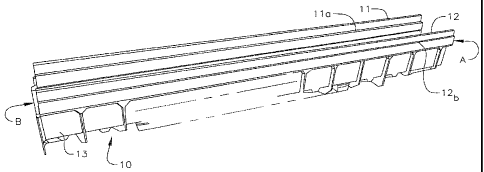
[0008] Fig. 1 is a side perspective view of a trench drain with sloping
overlay rails
according to one embodiment of the invention.
[0009] Fig. 2 is an end view of a trench drain with sloping overlay rails
according to one
embodiment of the invention.
[0010] Fig. 3 is a trench drain channel without sloping overlay rails
according to one
embodiment of the invention.
[0011] Fig. 4A is an overhead perspective view of the overlay rails according
to one
embodiment of the invention.
[0012] Fig. 4B is an overhead perspective view of an anchor clip according to
one
embodiment of the invention.
[0013] Fig. 5 is a side perspective view of a trench drain with sloping
overlay rails and
installed grating according to one embodiment of the invention.
[0014] Fig. 6 is a side perspective view of a channel bracket according to one
embodiment
of the invention.
[0015] Fig. 7 is an overhead perspective view of a channel bracket according
to one
embodiment of the invention.
2b
CA 02654859 2011-07-29
[0016] FIG. 8 is an overhead view of the underside of two sections of trench
drain
channel joined before adding a channel bracket according to one embodiment of
the
invention.
[0017] FIG. 9 is an overhead view of the underside of two sections of trench
drain
channel joined with a channel bracket according to one embodiment of the
invention.
[0018] FIGS. 10 A-D show various views of the lock device for the grates
according to
one embodiment of the invention.
DETAILED DESCRIPTION OF EXEMPLARY EMBODIMENTS
[0019] In one embodiment of the invention, a modular, non-sloping section of
trench
drain is transformed into a sloping section sloping trench drain by installing
sloping overlay
rails.
[0020] According to an embodiment of the invention, as shown in FIG. 1,
sloping
overlay rails 11, 12 are mounted on a non-sloping, modular trench drain
component 13 to
create a sloping trench drain 10. As shown in FIG. 3, the non-sloping modular
trench drain
component 20, comprises sidewalls 21 spaced apart by a width W, and a bottom
section 22.
Each sidewall 21 has an upper edge 24 and an inner shelf 23 below the upper
edge 24. There
is also a flange with a groove 25 at one end of the modular trench drain
component 20, which
flange may correspond to a "female" end and is dimensioned and adapted to
receive a
corresponding "male" end. The other end of the trench drain component 20, the
"male" end
(not shown), is dimensioned and adapted be inserted into the "female" end, to
make a tight
fitting joint. In an embodiment, the joint is held together with an adhesive
and is watertight.
The bottom of each overlay rail 11, 12 has an inverted U-shaped groove. As
shown in FIG. 2,
each overlay rail 11, 12 comprises an inner ledge 11 a, 12a respectively, and
an outer ledge
I Ib, 12b respectively. As shown in FIGS. 2 and 3, the bottom of the inner
ledge 1 if, 12f
rests on the top of the inner shelf 23 of the non-sloping modular trench drain
component 20.
[0021] In another embodiment, the vertical distance from the inner ledge l la,
12a, to the
top of the overlay rail l ld, 12d is constant throughout the length of the
overlay rail 11, 12. As
3
CA 02654859 2011-07-29
shown in FIG. 5, this allows grating 31 that is level with the top rail 32 to
be installed on the
sloping trench drain 30.
[0022] In an additional embodiment, as shown in FIGS. I and 2, the vertical
distance
from. 11 a, 12a to 11 If, 12f increases linearly from end A to end B, thereby
creating the sloped
trench drain 10. For the outside of the overlay rail 11, 12 the vertical
distance from the top of
the rail 11 d, 12d to the outer ledge I1 b, 12b increases as the slope
increases, and the distance
from the outer ledge I 1 b, 12b to the bottom of the outer leg 11 e, 12e is
constant. In one
embodiment the rail increases in height at a rate of 0.50% to 1.00%, and in
another
embodiment it increases in height at a rate of about 0.75%. Thus, for a 1
meter section of
trench drain having rails that increase in height at a rate of 0.75%, the
increase from end A to
end B would be about 0.0075 meters or about 0.295 inches. In another
embodiment, fifteen
different 1 meter sections of trench drain are connected together with sloping
overlay rails
having a 0.75% rate of increase in height, yielding a height differential of
0.1125 meters or
4.425 inches between the beginning of the first section and end of the last
section. In one
embodiment, the overlay rails are 1 mm shorter than the channel section to
allow for some
linear expansion, although a larger gap may be used.
[0023] According to one embodiment, as shown in FIG. 4A, each separate rail
41, 42 in
the matched pair 40 is a mirror image of the other. Each section of trench
channel will
require a different matched pair of overlay rails to create continuously
sloping trench drain
system. The height at the end of the overlay rail of the previous section of
trench drain
should correspond to the beginning height of the overlay rail of the next
section of trench
drain, so as to make a continuously sloping trench drain system. In another
embodiment, the
outside edge of each rail 41, 42 contains four anchor lugs 44, with center
openings 45. Each
rail 41, 42 may contain more or less than four anchor lugs 44. The lugs 44
enhance positive
anchoring during the concrete pour and the center the allows attachment of
wire mesh (not
shown) prior to the concrete pour. In yet another embodiment, the inside edge
of each rail 41,
42 contains two anchoring tabs 43 with a center hole 46. Each rail 41, 42 may
contain more
or less than two anchoring tabs 43. In one embodiment, an anchoring clip 50,
as shown in
FIG. 4B is inserted into an anchoring tab center hole 46 on a rail 41 and a
corresponding
center hole 46 on the opposite rail 42. The anchoring clip 50 assists in
maintaining a constant
distance between the two separate rails 41, 42. Thus, neither pressure exerted
inward from
4
CA 02654859 2011-07-29
poured concrete, nor pressure exerted outward from the molded draft of the
modular channel
will significantly change the upper span between the rails 41, 42.
[0024] In an embodiment, as shown in FIG. 4B, the anchoring clip 50 comprises
a top
47 plate with two pins 48, and a center hole 49. In one embodiment, the
distance between the
two pins 48 corresponds to the distance between the anchor tab center holes
46, opposite
each other on rails 41, 42. In yet another embodiment, the center hole 49 is
used for a grate
locking device and lines up with bolt holes 33 in the grating 31 as shown in
FIG. 5. In one
embodiment, the anchoring clip 50 is inserted into corresponding holes 46 with
the pins
facing down. If it is desired to use a grating lock device, the anchoring clip
50 may be
inserted with the pins facing up as discussed below with reference to FIGS. 1
OA-D.
[0025] In an embodiment, as shown in FIGS. 6-9, different sections of the
modular
trench drain component are joined together with brackets to create longer
sections of trench
drain. Note that the sloping overlay rails are not shown in FIGS. 8 and 9
because the Figs.
show the bottom portion of the trench drain system. As shown in FIG. 8, one
section of
modular trench drain channel 81 is joined to another section of trench drain
channel 82. In an
embodiment, trench drain channel 81 is the female end with a flange 83, and
trench drain
channel 82 is the male end with securing tabs 84. In one embodiment, trench
drain channel
82 has a circular cutout 87 for a round discharge pipe (not shown).
[0026] According to one embodiment, to secure and assist in stabilizing the
modular
trench drain, channel brackets 60 are used as shown in FIGS. 6 and 7. In an
embodiment, the
channel bracket 60 comprises a base 61, connected to two side walls 66, and
two anchor tabs
64 on the sidewalls 66. In one embodiment, each sidewall 66 has two grooves
62, 63,
dimensioned to receive flanges 83 or securing tabs 84 located on modular
trench channel
sections as shown on
5
CA 02654859 2008-12-08
WO 2007/146379 PCT/US2007/013957
Fig. 8. In another embodiment, only a portion of each sidewall is connected to
the base 61, and
one section containing one of the groves 63 is cantilevered from the base 61.
One of the
grooves 62 continues from the top of the clip down through the base 61 of the
clip. The other
groove 63 is only present on the cantilevered portion of the sidewall that is
not connected to the
base 61. In another embodiment, the anchor tabs 64 have two center holes 65
which are
dimensioned to receive a piece of rebar (not shown).
[00271 In an embodiment, as shown in Fig. 9, a channel bracket 85 is mounted
over a flange
(not shown) and a securing tab 84 to secure two sections of trench channel 81,
82 together.
Center holes 85 may receive rebar (not shown) to anchor the secured sections
prior to pouring
the concrete, as well as after the concrete has cured.
[0028]' In one embodiment, as shown in Figs. 1OA-D, a locking device 100 is
used to hold
down slotted grates and solid covers and comprises a bolt 101, a washer 102,
and a threaded
flange 103. In another embodiment, the flange may be used in conjunction with
the anchor clip
50 shown in Fig. 4B. The anchor clip 50 would be installed with the pins
facing up, and the
bolt 101 with a washer 102 would be inserted through a hole in the grating,
like hole 33 in Fig.
5, and the flange 103 would be placed under the anchor clip 50, so that the
bolt 101 may be
inserted into the threads 104 of the flange 103 and tightened.
[0029] Various materials may be used for the different components of the
trench drain
system. In one embodiment, the channel is constructed of fiberglass,
polypropylene,
polyethylene, polymer concrete, concrete, or combinations thereof. In another
embodiment, the
overlay rails may be constructed of polypropylene, polyethylene, or a
combination thereof. In a
further embodiment, the rails are constructed of the same material as the
channel, fiberglass,
polymer concrete, or combinations thereof. In one embodiment, the anchor clips
may be
constructed of PVC, plastic, steel, aluminum, and combinations thereof. In a
further
embodiment, polyurethane may be used as a sealer/adhesive between the channel
sections,
however any commonly known sealer in the art may be used. In an embodiment,
the grating
-6-
CA 02654859 2008-12-08
WO 2007/146379 PCT/US2007/013957
lock device is constructed out of stainless steel or galvanized steal,
although other materials
may be used for various parts such as plastics for the flange.
[00301 While this invention has been described in connection with what are
considered to
be exemplary embodiments, it is to be understood that the invention is not
limited to the
disclosed embodiments, dimensions, and configurations but, on the contrary,
also extends to
various modifications and equivalent arrangements. The invention is limited
only by the claims
and their equivalents.
20
-7-