Note: Descriptions are shown in the official language in which they were submitted.
CA 02657138 2009-01-07
WO 2008/008794
PCT/US2007/073182
RESILIENT DEVICE
BACKGROUND OF THE INVENTION
Field of the Invention
The present invention relates to a resilient device. More specifically,
this invention relates to a device that has a working portion having a
variable
equivalent diameter, and an anchoring mechanism. The device is useful,
e.g., for reducing or preventing urinary incontinence.
lo Description of the Prior Art
Stress urinary incontinence is a problem for many women. It is
characterized by leakage of urine during a stressing event, such as a cough
or a sneeze. Many devices have been designed to reduce or prevent stress
urinary incontinence. US Pat. No. 5,603,685 teaches inflatable devices and
a means to provide a device that is small for insertion into the vagina and
enlarges to a required shape and pressure to reduce or prevent urinary
incontinence. US Pat. No. 6,090,098 teaches tampon-like devices, each
made with a combination of absorbing and/or non-absorbing fibrous
materials. US Pat. No. 6,645,137 teaches a coil that expands in the vagina.
US Pat. No. 5,036,867 teaches a compressible resilient pessary. US Pat.
No. 6,460,542 teaches a highly shaped rigid pessary. Many patents are
drawn to stents that are sized and designed to keep arteries open.
Despite the teaching of the prior art, there is a continuing need for a
device suitable for insertion into a vagina and useful for reducing or
preventing urinary incontinence. In addition, a need exists to provide for
safe and secure anchoring of disposable intravaginal devices.
CA 02657138 2014-01-15
64160-411
- 2 -
SUMMARY OF THE INVENTION
We have addressed the needs discussed above with the present
invention. In one embodiment, an intravaginal device includes a working
portion and
an anchoring portion. The anchoring portion has at least one member extending
beyond at least one end of the working portion to maintain the working portion
in
place during use.
In another embodiment, an intravaginal urinary incontinence device
includes a stent having a working portion having opposed faces to provide
support to
an associated urinary system; and an anchoring portion to maintain the stent
in place
during use. The anchoring portion has at least one member extending beyond at
least one end of the working portion.
In another embodiment, there is provided an intravaginal urinary
incontinence device comprising: a) a stent comprising an elastic material
having a
working portion having a longitudinal axis and first and second generally
parallel
opposed faces defined by longitudinally extending struts, each strut having a
length
and wherein the opposed faces are arranged and configured to contact a user's
vaginal tissue and to provide support to an associated urinary system along
substantially all of the length of the longitudinally extending struts in such
tissue-contacting face, wherein the first and second opposed faces are
substantially
parallel to the longitudinal axis and wherein the working portion has a
diameter
measured as a maximum distance between the opposed faces; and b) an anchoring
portion to maintain the stent in place during use, the anchoring portion
having a width
dimension, wherein the anchoring portion has at least one member extending
beyond
at least one end of the working portion capable of engaging vaginal walls such
that
during use, the width dimension of the anchoring portion is larger than the
diameter of
the working portion, and a withdrawal element is operatively connected to and
extends from the working portion.
CA 02657138 2014-01-15 =
. 64160-411
- 2a -
In another embodiment, there is provided an intravaginal device
comprising a working portion having a longitudinal axis and first and second
generally
parallel outer faces defined by longitudinally extending struts; a diameter
measured
as a maximum distance between the outer faces; and an anchoring portion having
a
width dimension that during use is larger than the diameter of the working
portion, the
anchoring portion comprising at least one member extending longitudinally
beyond at
least one end of the working portion and returning to the working portion,
forming a
closed loop, to maintain the working portion in place during use.
In another embodiment, there is provided an intravaginal urinary
incontinence device comprising: a) a stent comprising an elastic material
having a
working portion comprising a wire form and having a longitudinal axis and
first and
second generally parallel opposed faces defined by longitudinally extending
struts
that at least partially extend in and define the opposed faces, the opposed
faces are
arranged and configured to provide support to an associated urinary system,
wherein
the first and second opposed faces are substantially parallel to the
longitudinal axis
and wherein the working portion has a diameter measured as a maximum distance
between the opposed faces; and b) an anchoring portion to maintain the stent
in
place during use, the anchoring portion having a width dimension, wherein the
anchoring portion has at least one member extending beyond at least one end of
the
working portion capable of engaging vaginal walls such that during use, the
width
dimension of the anchoring portion is larger than the diameter of the working
portion
and a withdrawal element comprises a withdrawal string, a proximal end of
which is
operatively connected to at least two of the struts that at least partially
define and
support the opposed faces and is arranged and configured such that tension on
a
distal end of the withdrawal string urges the opposed faces of the working
portion
together.
In another embodiment, there is provided an intravaginal device
comprising: a working portion comprising an elastic material formed into a
wire form
having a plurality of longitudinally extending struts that at least partially
define and
CA 02657138 2014-01-15
64160-411
- 2b -
support first and second generally parallel outer faces of the working
portion, the
working portion having a diameter measured as a maximum distance between the
outer faces, an anchoring portion having a width dimension that during use is
larger
than the diameter of the working portion, the anchoring portion comprising at
least
one member extending beyond at least one end of the working portion to
maintain the
working portion in place during use; and a withdrawal string, a proximal end
of which
is operatively connected to at least two of the struts that at least partially
define and
support the outer faces and is arranged and configured such that tension on a
distal
end of the withdrawal string urges the outer faces of the working portion
together.
In another embodiment, there is provided an intravaginal urinary
incontinence device comprising a working portion having first and second
generally
parallel opposed faces, an insertion equivalent diameter measured as a maximum
distance between the opposed faces ranging from about 10 to about 20 mm, and a
use equivalent diameter measured as a maximum distance between the opposed
faces that is greater than the insertion equivalent diameter and ranges from
about 20
to about 35 mm under an expansion pressure of about 20 to about 150 cm H20,
wherein a withdrawal element extends from the working portion.
In another embodiment, there is provided an intravaginal urinary
incontinence device having a longitudinal axis and comprising an elastic
working
portion comprising a plurality of longitudinally extending struts that at
least partially
define outer surfaces of the device having a first use equivalent diameter of
at least
about 15 mm under an expansion pressure of 20 cm H20, and a second use
equivalent diameter, wherein the second use equivalent diameter is about 5 to
about 25 mm under an expansion pressure of 100 cm H20 and is less than the
first
use equivalent diameter, wherein the diameters are measured as a maximum
distance between the outer surfaces of the device.
In another embodiment, there is provided an intravaginal urinary
incontinence device comprising: a) an elastic working portion comprising i)
opposed
CA 02657138 2014-01-15
64160-411
- 2c -
working surfaces to provide support to an associated urinary system; and ii) a
cushion comprising a soft, resilient material that is associated with each of
the
working surfaces; and b) an anchoring portion operatively connected to the
working
portion to maintain the working portion at a desired location within a user's
vagina;
wherein the anchoring portion has at least one looped member extending
longitudinally beyond at least one end of the working portion and returning to
the
working portion capable of engaging vaginal walls.
In another embodiment, there is provided a method of making an
intravaginal stent comprising the steps of: a) forming a working portion
comprising a
wire form comprising a plurality of longitudinally extending struts that at
least partially
extend in and define generally parallel anterior and posterior outer faces
that provide
support to an associated urinary system, wherein the wire form comprises an
elastic
material; b) forming an anchoring portion comprising a wire form comprising an
elastic material that extends from one end of the working portion and that is
capable
of maintaining the working portion in place during use; c) enclosing the wire
form of
each of the working portion and anchoring portion within a biocompatible
material;
d) attaching a withdrawal mechanism to a second end, opposite the first, of
the
working portion; e) enclosing the stent within a bag; and f) placing the
bagged stent in
an applicator for delivery into a vagina.
In another embodiment, there is provided a method of making an
intravaginal stent comprising the steps of: a) forming a working portion
comprising an
elastic material formed into a wire form having a plurality of struts that at
least
partially define and support anterior and posterior outer faces of the working
portion,
which faces are capable of providing support to an associated urinary system;
b) forming an anchoring portion comprising a wire form formed into at least
one loop
extending from and returning to the working portion and capable of maintaining
the
working portion in place during use; c) enclosing the wire form of each of the
working
portion and anchoring portion within a biocompatible material; d) operatively
connecting a proximal end of a withdrawal string to at least two struts of the
working
CA 02657138 2014-01-15
64160-411
- 2d -
portion such that tension on a distal end of the withdrawal string urges the
outer faces
of the working portion together; e) enclosing the stent within a bag; and f)
placing the
bagged stent in an applicator for delivery into the vagina.
In another embodiment, there is provided a method of making an
intravaginal stent comprising the steps of: a) forming a working portion
comprising a
wire form having opposed working surfaces to provide support to an associated
urinary system, wherein the wire form comprises an elastic material; b)
forming an
anchoring portion comprising a wire form capable of maintaining the working
portion
in place during use, wherein the anchoring portion comprises at least one
looped
member extending longitudinally beyond at least one end of the working portion
and
returning to the working portion; c) attaching a withdrawal mechanism to the
stent;
d) enclosing the stent within a sheet-like material; and e) placing the
enclosed stent in
an applicator for delivery into the vagina.
BRIEF DESCRIPTION OF THE DRAWINGS
FIG. 1 is a perspective view of a device according to the present
invention;
FIG. 2 is a perspective view of the device of FIG. 1 in the insertion state
while contained in an applicator.
FIG. 3 is a perspective view of the device of FIG. 1 in the use state.
FIG. 4 is a perspective view of a second device according to the
present invention;
FIG. 5 illustrates several plan views of an anchoring portion according
to the present invention;
FIG. 6A is a perspective view of a third device according to the present
invention;
CA 02657138 2014-01-15
64160-411
- 2e -
FIG. 6B is a side elevation of the device of FIG. 6A;
FIG. 7 is a side view of the device of FIG. 1;
FIG. 8 shows a bare wire form formed into an elastic structure and a
coated wire form;
CA 02657138 2009-01-07
WO 2008/008794
PCT/US2007/073182
- 3 -
FIG. 9A-9C shows three alternative embodiments of a composite
intravaginal device;FIG. 10 is a device in a bag that is useful for the
present
invention;
FIG. 11 illustrates a tool utilized to form the devices utilized in the
present invention;
FIG. 12 illustrates a tool utilized to heat-treat the devices utilized in
the present invention;
FIG. 13 shows a diameter vs. pressure curve for a straight stent and a
basket stent as described herein;
FIG. 14 shows a graph of the diameter versus pressure of a rabbit
and flower stent;
FIG. 15 shows a graph of the diameter versus pressure of three
different pressure levels of the flower stent; and
FIG. 16 shows a graph comparing the diameter versus pressure curve
of two different pressure levels of the flower stent against a hybrid foam-
wire
device.
DETAILED DESCRIPTION OF PREFERRED EMBODIMENTS
As used herein the specification and the claims, the term "wire form"
and variants thereof relate to a structure formed of at least one wire or wire-
like material that is manipulated and optionally secured (e.g., by welding) in
a desired three-dimensional structure.
As used herein the specification and the claims, the term "shape
memory material" and variants thereof relate to materials that can be shaped
into an initial shape, which initial shape can be subsequently formed into a
stable second shape. The material is capable of substantially reverting to its
initial shape upon exposure to an appropriate event, including without
limitation mechanical deformation and a change in temperature.
CA 02657138 2009-01-07
WO 2008/008794
PCT/US2007/073182
- 4 -
As used herein the specification and the claims, the term "stent" and
variants thereof relate to a device used to support a bodily orifice, cavity,
vessel, and the like. The stent is resilient, flexible, and collapsible with
memory. The stent may be any suitable form, including, but not limited to,
scaffolding, a slotted tube or a wire form.
As used herein, a "stent" is a device used to support a bodily orifice,
cavity, vessel, and the like. The stent is resilient, flexible, and
collapsible
with memory. The stent may be any suitable form, including, but not limited
to, scaffolding, a slotted tube or a wire form.
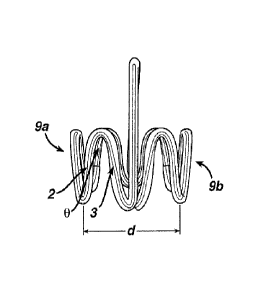
lo Referring to FIGs. 1-8, there is shown a device 10 according to
the
present invention. The device 10 has a working portion 1 which is generally
cylindrical in shape and contains working surfaces 9a and 9b. Working
portion 1 has an initial equivalent diameter d ranging from about 20 mm to
about 170 mm and a length L1 ranging from about 15 mm to about 60 mm.
Where the working portion is non-cylindrical, the equivalent diameter is the
maximum distance in millimeters between the opposed working surfaces.
As seen in FIG. 2, working portion 1 has an insertion (in an applicator or
other device for insertion) equivalent diameter d 2 ranging from about 5 mm
to about 20 mm. As seen in FIG. 3, working portion 1 has a use equivalent
diameter (in the vagina) d 3 ranging from about 5 mm to about 40 mm.
Working portion 1 may be made of any elastic material that compresses and
recovers with sufficient force to provide the desired effect. In one
embodiment, the working portion 1 is made of Nitinol wire 20 and comprises
alternating sinusoidal struts 2, 3 which intersect and form a strut angle B.
Alternating struts 2, 3 have a length L2 and L3 equal to the working portion
length. The working pressure exerted by working portion 1 is determined by
the thickness of the wire, the number of wires, the length of the struts and
the strut angle, and the number of times the working portion is heat-treated.
The number of wires may range from about 1 to about 20. The wires may be
CA 02657138 2009-01-07
WO 2008/008794
PCT/US2007/073182
- 5 -
separate, twisted, or braided. For some applications, the working portion
exerts a pressure of from about 5 to about 250 cm H20 in the working state.
Device 10 may also have an anchoring means, e.g., anchoring portion 4.
Anchoring portion 4 is designed to keep the device in place when in use.
Anchoring portion 4 is shaped suitable to keep the device in place while in
use. Suitable shapes include, but are not limited to, a basket handle 5,
rabbit ears 6, and a dog bone 7, as shown in FIG. 5. The anchoring portion
may be made of the same material as the working portion or they may be
made of different materials. The working portion and anchoring portion may
lo be made as a uni-body construction, or may be made separately and joined
by attachment means, such as silicone tubing 22. The devices may be
treated to provide improved biocompatibility. The device may be placed
inside tubing, for example silicone tubing, or may be dip coated in suitable
polymeric materials.
Devices according to the present invention may be useful for treating
or preventing urinary incontinence. For this application, the device is sized
to fit comfortably in the vagina. All of the devices described below may have
working portions with initial equivalent diameters of from about 20 to about
170 mm. Preferably, the working portion has a generally cylindrical working
portion that may have an initial equivalent diameter ranging from about 20 to
about 170 mm, preferably about 20 to about 45 mm, or more preferably
about 30 mm; an insertion equivalent diameter ranging from about 5 to about
mm, preferably about 10 to about 20 mm, or more preferably about 18
mm; a use equivalent diameter ranging from about 20 to about 40 mm,
25 preferably about 25 to about 30 mm, or more preferably about 25 mm; and
a
length ranging from about 20 to about 60 mm, preferably about 20 to about
mm, or more preferably about 25 mm. The anchoring portion extends
beyond the working portion and may have an initial equivalent diameter
ranging from about 20 to about 60 mm, preferably about 40 to about 60 mm,
CA 02657138 2009-01-07
WO 2008/008794
PCT/US2007/073182
- 6 -
or more preferably about 50 mm; an insertion equivalent diameter ranging
from about 10 to about 25 mm, preferably about 10 to about 20 mm, or more
preferably about 18 mm; a use equivalent diameter ranging from about 20 to
about 60 mm, preferably about 40 to about 60 mm, or more preferably about
50 mm; and a length ranging from about 10 to about 50 mm, preferably
about 20 to about 40 mm, or more preferably about 30 mm.
For a basket stent, the working portion of the device has a length and
equivalent diameter in the insertion state, the working state, and the removal
state. The insertion state length may range from about 20 to about 30 mm,
lo for example about 25 mm. The insertion state equivalent diameter may
range from about 5 to about 20 mm, for example about 18 mm. The working
state length at rest and during a cough may range from about 20 to about 30
mm, for example about 25 mm. The working state equivalent diameter at
rest may range from about 20 to about 30 mm, for example about 25 mm.
The working state equivalent diameter during a cough may range from about
15 to about 25 mm, for example about 20 mm. The removal state length
may range from about 20 to about 30 mm, for example about 25 mm. The
removal state equivalent diameter may range from about 15 to about 20 mm,
for example about 18 mm.
The anchoring portion of the device has a length and width in the
insertion state, the working state, and the removal state. The insertion state
length may range from about 25 to about 40 mm, for example about 30 mm.
The insertion state width may range from about 15 to about 20 mm, for
example about 18 mm. The working state length at rest and during a cough
may range from about 25 to about 40 mm, for example about 30 mm. The
working state width at rest and during a cough may range from about 25 to
about 35 mm, for example about 30 mm. The removal state length may
range from about 30 to about 50 mm, for example about 40 mm. The
CA 02657138 2009-01-07
WO 2008/008794
PCT/US2007/073182
- 7 -
removal state width may range from about 15 to about 20 mm, for example
about 18 mm.
For a straight stent, the working portion of the device has a length and
equivalent diameter in the insertion state, the working state, and the removal
state. The insertion state length may range from about 25 to about 60 mm,
for example about 45 mm. The insertion state equivalent diameter may
range from about 5 to about 20 mm, for example about 18 mm. The working
state length at rest and during a cough may range from about 25 to about 60
mm, for example about 45 mm. The working state equivalent diameter at
lo rest may range from about 20 to about 30 mm, for example about 25 mm.
The working state equivalent diameter during a cough may range from about
to about 25 mm, for example about 20 mm. The removal state length
may range from about 25 to about 60 mm, for example about 45 mm. The
removal state equivalent diameter may range from about 15 to about 20 mm,
15 for example about 18 mm.
For a rabbit stent, the working portion of the device has a length and
equivalent diameter in the insertion state, the working state, and the removal
state. The insertion state length may range from about 20 to about 30 mm,
for example about 25 mm. The insertion state equivalent diameter may
range from about 10 to about 20 mm, for example about 15 mm. The
working state length at rest and during a cough may range from about 20 to
about 30 mm, for example about 25 mm. The working state equivalent
diameter at rest and during a cough may range from about 10 to about 30
mm, for example about 18 mm. The removal state length may range from
about 20 to about 30 mm, for example about 25 mm. The removal state
equivalent diameter may range from about 10 to about 20 mm, for example
about 15 mm. The height of the working portion in all states may range from
about 20 to about 30 mm, for example about 25 mm.
CA 02657138 2009-01-07
WO 2008/008794
PCT/US2007/073182
- 8 -
The anchoring portion of the device has a length and width in the
insertion state, the working state, and the removal state. The insertion state
length may range from about 20 to about 50 mm, for example about 30 mm.
The insertion width may range from about 10 to about 20 mm, for example
about 18 mm. The working state length at rest and during a cough may
range from about 20 to about 50 mm, for example about 30 mm. The
working state width at rest and during a cough may range from about 20 to
about 60 mm, for example about 50 mm at the top and from about 10 to
about 50 mm, for example about 25 mm at the bottom. The removal state
lo length may range from about 20 to about 50 mm, for example about 30 mm.
The removal state width may range from about 10 to about 20 mm, for
example about 18 mm.
For a flower stent, the working portion of the device has a length and
equivalent diameter in the insertion state, the working state, and the removal
state. The insertion state length may range from about 20 to about 30 mm,
for example about 25 mm. The insertion state equivalent diameter may
range from about 10 to about 20 mm, for example about 15 mm. The
working state length at rest and during a cough may range from about 20 to
about 30 mm, for example about 25 mm. The working state equivalent
diameter at rest may range from about 20 to about 35 mm, for example
about 25 mm. The working state equivalent diameter during a cough may
range from about 15 to about 30 mm, for example about 20 mm. The
removal state length may range from about 20 to about 30 mm, for example
about 25 mm. The removal state equivalent diameter may range from about
10 to about 20 mm, for example about 15 mm.
The anchoring portion of the device has a length and width in the
insertion state, the working state, and the removal state. The insertion state
length may range from about 20 to about 50 mm, for example about 30 mm.
The insertion width may range from about 10 to about 20 mm, for example
CA 02657138 2009-01-07
WO 2008/008794
PCT/US2007/073182
- 9 -
about 18 mm. The working state length at rest and during a cough may
range from about 20 to about 60 mm, for example about 30 mm. The
working state width at rest and during a cough may range from about 20 to
about 60 mm, for example about 30 mm at the top and from about 10 to
about 50 mm, for example about 20 mm at the bottom. The removal state
length may range from about 20 to about 60 mm, for example about 30 mm.
The removal state width may range from about 10 to about 20 mm, for
example about 18 mm.
In one embodiment of the present invention, the working portion of the
intravaginal devices is a stent. In other embodiments, the working portion
may be a suppository, a vaginal tampon, a bladder support, and a
combination thereof. Elements of the devices of the present invention may
be made from any elastic or supereleastic material. Suitable materials
include, but are not limited to metals including metal alloys, for example a
nickel-titanium ("NiTi") alloy known in the art as Nitinol. As is known in the
art, there are a variety of ways to process NiTi, including resistance heating
and permanent deformation to create a shape set. Other materials (other
alloys, superelastic alloys or other NiTi compositions) may be utilized to
make devices according to the present invention. Additionally, polymers
including shape memory polymers (SMPs) may also be used in addition to or
in place of the metals.
Shape memory is the ability of a material to remember its original
shape, either after mechanical deformation, which is a one-way effect, or by
cooling and heating which is a two-way effect. This phenomenon is based
on a structural phase transformation. The first materials to have these
properties were shape memory metal alloys including NiTi (Nitinol), CuZnAl
(the first copper based SMA to be commercially exploited and the alloys
typically contain 15-30 wt% Zn and 3-7 wt% Al), CuAlNi (may now be
preferred to the CuZnAl; Cu13A14Ni is one that is often used commercially),
CA 02657138 2009-01-07
WO 2008/008794
PCT/US2007/073182
- 10 -
CuAlBe (a Cu12A1 doped with less than 0.5% of beryllium), and FeNiAl
alloys. Strains of up to about 10% can be fully recovered in these alloys.
Examples of suitable alloys further include Algiloy, Stainless Steel, for
example 304 stainless steel, and carbon spring steels. The structure phase
transformation of these materials is known as martensitic transformation.
SMPs are light, high in shape memory recovery ability, easy to
manipulate and process, and economical compared to shape memory alloys.
These materials are also useful for devices according to the present
invention. There are few ways to achieve the shape memory properties.
SMPs are characterized as phase segregated linear block co-polymers (e.g.,
thermoplastic elastomers) having a hard segment and soft segment that
form physical cross-links. The hard segment is typically crystalline with a
defined melting point, and the soft segment is typically amorphous with a
defined glass transition temperature. The transition temperature of the soft
segment is substantially less than the transition temperature of the hard
segment. Examples of these materials include polyurethanes; polyether
amides; polyether ester; polyester urethanes; polyether urethanes; and
polyurethane/urea. SMPs are also formed by covalently cross-linked
irreversible formation of the permanent shape. Different parameters that can
be tailored for these materials are mechanical properties of permanent and
temporary shape, customized thermal transitions, and kinetics of shape
memory effect. SMPs can be biostable and bioabsorbable. Biostable SMPs
are generally polyurethanes, polyethers, polyacrylates, polyamides,
polysiloxanes, and their copolymers. Bioabsorbable SMPs are relatively
new and include thermoplastic and thermoset materials. Shape memory
thermosets may include poly (caprolactone) dimethyacrylates; and shape
memory thermoplastics may include combinations of different monomers to
prepare polyester based copolymers.
CA 02657138 2009-01-07
WO 2008/008794
PCT/US2007/073182
- 11 -
When the SMP is heated above the melting point of the hard
segment, the material can be shaped. This "original" shape can be
memorized by cooling the SMP below the melting point of the hard segment.
When the shaped SMP is cooled below the glass transition temperature of
the soft segment while the shape is deformed, a new "temporary" shape is
fixed. The original shape is recovered by heating the material above the
glass transition temperature of the soft segment but below the melting point
of the hard segment. The recovery of the original shape induced by an
increase of temperature is called the thermal shape memory effect. Several
lo physical properties of SMPs other than ability to memorize shape are
significantly altered in response to external changes in temperature and
stress, particularly at the glass transition of the soft segment. These
properties include elastic modulus, hardness, and flexibility. The modulus of
SMP can change by a factor of up to 200 when heated above the glass
transition temperature of the soft segment. In order to prepare devices that
will have sufficient stiffness, it is necessary to have thermal transitions
such
that the material will have high modulus at use temperature. For example, if
a device is going to be used at body temperature, then the transition
temperature may be higher than 37 C (example 45-50 C) so that upon
cooling to 37 C the modulus is high and thereby providing sufficient
stiffness. It is also important to design the device such that it will
compensate for lower physical properties compared to shape memory metal
alloys. Some of the design features may include higher wall thickness; short
connectors; or hinge points at appropriate locations. These materials can
overcome some of the limitations with viscoelastic polymer properties such
as creep and stress relaxation.
SMP can also be prepared by using TPEs prepared from hydrophilic
polymers so that the phase transition can be also occur by physical changes
due to moisture absorption. Examples of these TPEs are hydrophilic
CA 02657138 2009-01-07
WO 2008/008794
PCT/US2007/073182
- 12 -
polymer ester amide (Pebax) and hydrophilic polyurethanes prepared by Elf
Atochem and CardioTec International, respectively. Devices prepared from
these materials will be soft and will be easier to remove after its use.
The shape memory materials may be formed of or at least enclosed
within biocompatible materials, preferably materials that are approved for
use in the human body. For example, medical grade silicone rubber may
enclose a wire form device. This may be achieved through one or more
tubular sheaths about the wire or as a coating prepared on the wire.
As indicated above, the device may be made as a uni-body
lo construction, or it may be a composite device, e.g., the working portion
and
anchoring portion may be made separately and joined by attachment means,
such as silicone tubing. Additional elements features may be included to
provide desired characteristics. In addition to improved biocompatibility,
polymeric materials may cushion the device to minimize the risk of tissue
damage.
For example, each working surface may have a pad 30 to distribute
the forces directed toward the vaginal walls, thereby reducing the unit
pressure applied by the device. This soft, resilient cushion could be made
out of various types of medical grade sponges and foams (such as those
formed from HYPOLTM Hydrophilic Polyurethane Prepolymers from Dow
Chemical Company), thermoplastic elastomers ("TPE"), silicones, fibers, and
the like.
As shown in FIG. 8, the device includes a wire form 50 formed into an
elastic structure having an anchoring portion 52 and a working portion 54.
The wire form 50 has a biocompatible polymer coating 56 disposed thereon.
In the device of FIG. 8, the coating 56 has enlarged regions, each forming a
pad 58 on one of the working surfaces of the working portion 54.
In the alternative embodiments shown in FIG. 9A, the device may
replace the full coating of FIG. 8 with tubing 56' and a single compressible
CA 02657138 2014-01-15
64160-411
- 13 -
foam working portion 54'. The embodiment of FIG. 9B, employs two
separate pad elements 58" as the working portion 54". The wire form 50"
that extends to form the anchoring portion 52" provides elasticity to the pad
elements 58" to support the urinary system. The embodiment of FIG. 96
incorporates the Rabbit stent anchoring portion 52" and replaces the
working portion wire form with an enlarged pad structure 54"'. Again, this
enlarged pad structure may be formed of any appropriate resilient material
including foams, fibrous structures, and the like.
In addition, the pessary 10 may be loaded with various
io pharmacological compounds and additives, such as hormones and/or alpha-
adrenoceptor agonists, urethra selective stimulators, prostaglandins,
anticholinergics, hormones, nicotine, cytostatics, tranquilizers, local
anaesthetics and other compounds, such as pharmacologically active alpha-
Rertiary-aminomethylj-benzenemethanol derivatives and other compounds
as disclosed in US Pat. No. 5,527,821 to Willman et al., as well as toxin
inhibitors such as glyceryl monolaurate and related compounds as disclosed
in Brown-Skrobot et al., US Pat. No. 5,547,985.
Methods of associating drugs, hormones or other pharmacological
compounds with an object for drug administration to the body are well known
to those skilled in the art, as for example, described in US Pat.
No. 5,188,835 and German Patent No. 198 29 713.
In still a further embodiment, topical
medications, ointments or creams can be associated with pessary 10 by
infusion (injection), coating or absorption into the pores of a sponge-like
material of the medication of the pessary 10 and slowly released, within a
day or two, into the vaginal cavity. This embodiment of the invention may be
used for treating dryness, irritation, or other local conditions. The
ointment,
cream, etc., can be replenished into the pessary on an as needed basis.
CA 02657138 2009-01-07
WO 2008/008794
PCT/US2007/073182
- 14 -
As shown in FIG. 10, the intravaginal devices also may be enclosed in
a sheet-like material 60 that may reduce friction during deployment, shield a
wire form from view (to be aesthetically pleasing), help control the device
during insertion and removal, help the device to stay in place, contain
absorbent fibers of a tampon, contain a suppository substance, and/or create
more contact area for applying pressure to the bladder neck. The sheet-like
material may be formed into a cover or flexible bag 62 that may also provide
increased friction against the vaginal epithelium in comparison to a silicone-
lo coated wire form to reduce the likelihood of undesired movement during
use,
e.g., becoming skewed. Any medically appropriate sheet-like materials may
be used to form the cover or bag, and depending upon the desired end-use,
it may be opaque, light, and/or breathable. Useful sheet-like materials
include those used in the manufacture of tampons, such as nonwoven
fabrics and plastic film, including apertured films. The cover or bag itself
may also be apertu red.
The device preferably includes a withdrawal element such as a
removal string 64. This may be crisscrossed between the struts of the
device to create a "cinch sac" mechanism. Any string or cord known in the
sanitary protection art may be useful for this purpose. As the strings are
pulled during removal, the struts are gathered together to create a smaller
diameter device during removal. Cinching the device at its base may make
removal of the device more comfortable and easier as it makes the diameter
of the device smaller and the shape conducive to remove easily.
The device may be contained within an applicator 66 similar to those
known for use in delivering tampons and suppositories as shown in FIG. 2.
The applicator may be a push-type applicator or a retractable applicator. A
collar 68 may be added to control the depth of insertion.
CA 02657138 2009-01-07
WO 2008/008794
PCT/US2007/073182
- 15 -
Examples
The following examples are illustrative of devices according to the
present invention. The claims should not be construed to be limited to the
details thereof.
Prototype devices were modeled in shape and scale after existing,
predicate vaginal pessary devices. There were two geometries presented
for this device. The expanded stent device was approximately 35 mm in
diameter and 55 mm long. The first of the proposed geometries was a
simple S-shaped stent like a ring; the second resembled the form of a
lo handled basket and was modeled in the form of the classic "ring"
pessary. In
its design the "basket" portion was approximately 25 mm high and the
"handle" made up the balance of the overall length.
Both are assemblies of four known medical materials. The collapsed
vaginal stents were enclosed in a commercial plastic tampon applicator. The
working assemblies were made up of a nickel-titanium wire form (Nitinol),
which was covered by a medical grade silicone rubber (silastic) tube. This
covered wire form "stent" was placed in a heat-sealed bag made of the same
standard non-woven polypropylene material used in tampon covers. This
covered device was made to be easily removable by the addition of a
tampon cotton string, as a cinch and removal pull.
The nickel-titanium wire used in these prototypes was the same alloy
as used in vascular systems. Post-shape-setting processing of the metal
does not effect corrosion and biocompatibility of the device. The silicone
tubing was also a known medical grade material. The silastic tubing was
Dow Q7-4750.
The general procedure was to shape an 5E508 NiTi into the design
on a form using one or multiple steps heating the fixture and form to about
500 C for at least one minute for each step. Any excess wire was cut from
the form. As is known in the art, the wire may be chemically etched to
CA 02657138 2009-01-07
WO 2008/008794
PCT/US2007/073182
- 16 -
provide further biocompatibility. The wire was enclosed in a rubbery polymer
coating such as silicone assuring to fasten the wire ends such that they may
not puncture the surface.
Example 1 - Rabbit Flat Pessary
Approximately 1 foot of straightened and etched SE508 wire, 0.0315"
diameter was obtained. The tool 100 pictured in FIG. 11 was made using
conventional techniques known in stent art. In a smooth upswing, the wire
was wrapped around the pins in the following order to create the pattern: P7,
P3, P1CC, P3, P6CC, P3, P6, P4, P8CC, P5, P8, P5, P2CC, P5, P7, P1CC,
P3, P7 (the wrapping was clockwise, unless indicated by "CC"). The zigzag
wrapping pattern was smoothly discontinued and the final end of the wire
was poked through holes in the fixture to secure it. A large hose clamp was
wrapped around the fixture, over the zigzag portion. The clamp was
tightened to keep the wires in position, but not so much as to compress the
wires to the surface of the fixture. The wound wire was heat treated on the
fixture for 3 minutes in a 505C (calibrated) salt pot, then quenched with
water. The heat-treated wire was removed from the fixture by unwinding it.
The wire was trimmed at point P3 allowing for overlap along the "ear" and
the overlapping wires were wrapped to hold them together with NiCr wire. A
secondary heat treatment fixture 102 shown in FIG. 12 was made according
to methods known in the art. The wire was aligned to form onto the fixture.
The ends of the wire were ground to remove sharp and jagged edges.
The wire form component was passivated by methods known in the
art to optimize biocompatibility. Some wire form components were etched or
chemically processed to optimize biocompatibility. The parts were moved to
a clean room and dipped in denatured alcohol before being placed on a
clean table. All tools were cleaned with isopropyl alcohol as well as gloved
hands before touching parts from denatured alcohol solution. Tubing was
CA 02657138 2009-01-07
WO 2008/008794
PCT/US2007/073182
- 17 -
cleaned with Isopropyl alcohol by dripping through with a disposable pipette.
The tube was dried by wicking onto a paper towel. The tube was filled with
2-4 inches of lubricant mineral oil from a syringe. Pressed fingers were run
along the tube to spread the oil evenly along the inside. The tubing was slid
over the wire carefully paying attention that the wire ends did not poke
through the tubing. The tubing was pulled back to expose both wire ends.
The ends were lined up so that the ear rests naturally. Forceps were used to
hold the tubing back from the wire ends. Shrink tube was placed across the
wire ends and heated to hold wire ends in place. The tubing was slid over
lo the shrink tube section. Tubing ends were overlapped by at least 0.5 cm
by
pressing the ends together.
Example 2 - Flower Flat Pessary
Approximately 1 foot of straightened and etched 5E508 wire, 0.0315"
diameter was obtained. The tool 100 pictured in FIG. 11 was made using
conventional techniques known in stent art. In a smooth upswing, the wire
was wrapped around the pins in the following order to create the pattern: P6,
P3, P1CC, P3, P6, P4, P7, P6, P3, P1CC, P3, P6, P4, P7, P5, P2CC, P5,
P7, P4, P6, P3, P1CC, P3, P5, P2CC, P5, P7, P4, P6, P3, P1CC, and P3.
The zigzag-wrapping pattern was smoothly discontinued and the final end of
the wire was poked through holes in the fixture to secure it. A large hose
clamp was wrapped around the fixture, over the zigzag portion. The clamp
was tightened to keep the wires in position, but not so much as to compress
the wires to the surface of the fixture. The wound wire was heat treated on
the fixture for 3 minutes in a 505C (calibrated) salt pot, then quenched with
water. The heat-treated wire was removed from the fixture by unwinding it.
The wire was trimmed at point P3 allowing for overlap along the "ear" and
the overlapping wires were wrapped to hold them together with NiCr wire. A
secondary heat treatment fixture 102 shown in FIG. 12 was made according
CA 02657138 2009-01-07
WO 2008/008794
PCT/US2007/073182
- 18 -
to methods known in the art. The wire was aligned to form onto the fixture.
The ends of the wire were ground to remove sharp and jagged edges. The
wire form component was passivated by methods known in the art to
optimize biocompatibility. Some wire form components were etched or
chemically processed to optimize biocompatibility. The parts were moved to
a clean room and dipped in denatured alcohol before being placed on a
clean table. All tools were cleaned with isopropyl alcohol as well as gloved
hands before touching parts from denatured alcohol solution. Tubing was
cleaned with Isopropyl alcohol by dripping through with a disposable pipette.
lo The tube was dried by wicking onto a paper towel. The tube was filled
with
2-4 inches of lubricant mineral oil from a syringe. Pressed fingers were run
along the tube to spread the oil evenly along the inside. The tubing was slid
over the wire carefully paying attention that the wire ends did not poke
through the tubing. The tubing was pulled back to expose both wire ends.
The ends were lined up so that the ear rests naturally. Forceps were used to
hold the tubing back from the wire ends. Shrink tube was placed across the
wire ends and heated to hold wire ends in place. The tubing was slid over
the shrink tube section. Tubing ends were overlapped by at least 0.5 cm by
pressing the ends together.
Example 3 - Multi-wire Flower Pessary
The level of severity of incontinence varies greatly from woman to
woman and changes throughout a woman's life. Mechanically, this level is
determined by the support of the pelvic floor musculature. When this muscle
system is weakened, the urethra does not properly close when intra-
abdominal pressure is exerted onto the bladder. In order to address the
various levels of support of the pelvic floor musculature, there are three
pressure levels of the device: Pressure 1 (for women who need minimal
CA 02657138 2009-01-07
WO 2008/008794
PCT/US2007/073182
- 19 -
amount of support), Pressure 2 (for moderate support), and Pressure 3 (for
women who need the greatest support).
To test this concept, the device of Example 2 was reproduced in
these three different pressure levels: Pressure 1 was formed with two wires
generally as described above in Example 2; Pressure 2 was formed with
three wires; and Pressure 4 was formed with four wires.
Example 4 ¨ Composite Flower Pessary
lo The device of Example 2 was reproduced with the wire form working
portion with a pair of separate foam pad elements. The wire form that
extends to form the anchoring portion provides elasticity to the pad elements
to support the urinary system.
Examples 1-4:
Each of the exemplary devices were tested to determine the outward
pressure exerted as it expands from a compressed state as described
below, and the resulting diameter vs. pressure curves are shown in FIGS.
13-16.
Expansion Pressure Test
The expansion pressure test was used to determine the outward
pressure the device was able to exert as it expanded from its compressed
insertion state to its deployed or use state in the body. Equilibrium of the
expansion pressure and the internal resistance of the body determined the
diameter of the device in place.
The outward pressure the device exerts at various compression
states (insertion, during use at rest, and during use under stress) was
measured using a simple linear scale (Mettler PK 4800 scale). The pressure
CA 02657138 2009-01-07
WO 2008/008794
PCT/US2007/073182
- 20 -
the device exerted as well as the diameter of the device were measured and
recorded.
The device is tested by placing the device between the scale and a
custom-made arm that compresses the device at known, incremental
distances, measured in mm. The device was measured first at its free state
(i.e., for rabbit: 20 mm) and then slowly compressed in increments (i.e. 1 mm
or 5 mm). The force that the device exerts on the scale at known
compression increments was measured in grams. The pressure was
calculated by converting the force measurement from grams to pounds-
lo force. The pounds-force was then converted to PSI units by dividing the
pound-force by the contact area of the device. The contact area of the
device was defined as the working portion of the device. The PSI units were
then converted into cm H20 pressure. The resulting device diameter (mm)
versus pressure (cm H20) was then graphed.
This Pressure Curve Slope illustrates outward pressure that the
device exerts on the body varies with device compression. This pressure
increases as compression increases and reduces as the device is unloaded.
This is an important behavior of our device because at rest, the pressure in
the vagina is low (approximately 35 cm H20). When a woman has a stress
event such as coughing or sneezing, high intra-abdominal pressure as much
as over 140 cm H20 is exerted on the bladder in a very short time period.
When this event occurs, the device needs to quickly react to this sudden
increase in pressure.
When the device is at rest, the device is compressed to about 20-25
mm. When a sudden intra-abdominal pressure is exerted on the device, the
device is compressed down to 10-15 mm. At rest, it is important to that the
pressure that the device exerts on the body is low for comfort and safety.
When the device is compressed during high intra-abdominal pressure
CA 02657138 2009-01-07
WO 2008/008794 PCT/US2007/073182
- 21 -
events, the device needs to exert adequate pressure quickly and then relax
to its original low resting pressure when the stress event is completed.
The devices similar to those of Example 3 may be used to illustrate
the desired dynamic elasticity of the intravaginal urinary incontinence
device.
The following table illustrates desired Expansion Pressure targets when the
Low-, Medium-, and High-support devices are compressed to the specified
diameter - e.g., a Resting Diameter of 25 mm or a Compressed Diameter of
mm.
Pressure at 25 mm Pressure at 10 mm
# of Resting Diameter
Compressed Diameter
Device Wires (cm H20) (cm H20)
Low 2 25 100
Moderate 3 50 175
High 4 75 225
lo More
generally, the elastic working portion preferably has a first use
equivalent diameter (a "Resting Diameter") of at least about 15 mm under an
expansion pressure of 20 cm H20. This reflects the device under normal
use conditions. A more preferred first use equivalent diameter is at least
about 20 mm under an expansion pressure of 35 cm H20.
A second use equivalent diameter of about 5 to about 25 mm under
an expansion pressure of 100 cm H20 reflects the device under stress use
conditions, such as a sneeze. A more preferred second use equivalent
diameter is at least about 10 mm under an expansion pressure of 140 cm
H20.
Preferably, the second use equivalent diameter is less than the first
use equivalent diameter. More preferably, the second use equivalent
diameter is less than the first use equivalent diameter and at least about
20% of the first use equivalent diameter.
A third use equivalent diameter of about 10 to about 20 under expansion
pressure of 150 cm H20 reflects severe stress use conditions.