Note: Descriptions are shown in the official language in which they were submitted.
CA 02659347 2009-01-28
WO 2008/026085 PCT/IB2007/052055
Percutaneous Gastrointestinal Anchoring Kit
BACKGROUND OF THE INVENTION
The present invention relates to pre-packaged surgical kits in general, and
more particularly
to surgical kits for percutaneous gastrointestinal anchoring procedures or a
gastropexy kit.
Various medical procedures are simplified by providing the physician with a
kit that contains
the majority, if not all, of the necessary medical articles that the physician
will need to
complete a particular procedure. Kits may include articles such as, for
example, drapes,
syringes, scalpels, needles, clamps, gauze, sponges, drugs, sutures, and
devices. Such kits are
commonly provided for procedures such as, for example, percutaneous endoscopic
gastrostomy ("PEG") and laparoscopic jejunostomy. These kits reduce the time
spent by
hospital personnel gathering the appropriate articles that are required for a
particular
procedure and ensure that the surgeon has each article at hand at the
appropriate point in
the procedure.
A PEG procedure is utilized to place a feeding tube into a patient that
extends from the
interior of the patient's stomach exteriorly of the patient. The feeding tube
permits nutrients
to be placed directly into a patient's stomach. This may be necessary when a
patient has a
disorder of the gastrointestinal tract, malabsorption (impaired absorption of
nutrients,
vitamins or minerals from the diet by the lining of the small intestine), or
neurological or
renal disorders. The feeding tube inserted using a PEG procedure is kept in
place until a
stoma is formed. Once a stoma is formed, the PEG feeding tube may be removed
and
replaced with an alternate feeding device.
Prior to placement of any feeding tube, it has been found that it is
particularly desirable to
anchor the anterior wall of the stomach to the abdominal wall as a step prior
to creating the
stoma tract through the two. This attachment has been found to be critical as
it helps to
prevent inadvertent separation and exposure of the peritoneal cavity to
contamination and
possible peritonitis.
Typically a T-shaped fastener or anchor is percutaneously introduced into the
gastric lumen
or stomach. This fastener consists of wire or other filament affixed to a
small metal bar or
rod. The point at which the two are conjoined is at the center of the bar. The
overall visual
look of the device is that of the letter "T", with the wire forming the
vertical component and
the bar forming the horizontal or cross component. The device is typically
loaded into an
1
CA 02659347 2009-01-28
WO 2008/026085 PCT/IB2007/052055
introducer needle or the like with the rod pivoted at the connection with the
wire so that the
two are essentially in alignment. The introducer is inserted into the stomach,
the wire pushed
distally from the introducer until the horizontal bar is deployed at which
time it at least
partially pivots into the T-configuration. The introducer is retracted from
the stomach and a
tractive force is applied to the wire, the T-component seats against the wall
of the stomach
and continued pulling serves to draw the anterior wall of the stomach to the
abdominal wall.
Although these devices perform the function that they are designed for, a
number of
problems do exist with them. Typically the T-shaped fastener or horizontal T-
bar is not
removable back through the incision. As such once the procedure has been
completed and
the device ready to be removed, the wire is typically cut and the T-bar is
left in the body
cavity where it is allowed to pass naturally in the patient's stool. In many
cases the T-bar is
not passed and remains within the body cavity. Consequently, in many cases
these initial
placement devices are often not readily removable without additional invasive
surgical
procedures. This is further complicated by the fact that during the six to
eight weeks it takes
for the fistula's stoma tract to be established, the anchoring mechanism i.e.,
the small metal
T-shaped fastener may embed itself into the gastric or intestinal wall and
ultimately lead to
infection. Furthermore, the edges of the T-bar often irritate the stomach
lining which can be
uncomfortable for the patient. Although these devices are often formed of
stainless steel,
hydrochloric acid contained within the gastric juices of the patient may cause
some minor
erosion to the device due to the time in which the device is maintained in
place.
As described above, in order to achieve the desired seal between the stomach
and the
abdominal wall, a tractive force must be applied to the anchoring mechanism.
This force is
applied in such a way so as to pull the stomach cavity to the abdominal wall
in order to
induce the penetration through the tissue layers to fuse or heal together thus
creating the
passage or stoma leading from the patient's stomach to an external
environment.
Accordingly, it is necessary to apply this tractive force for a period of a
couple of days
through a couple of weeks until the stoma site adequately heals. During this
period the
patient has reduced mobility which may lead to additional post operative
complications.
While gastropexy devices do exist, there is a need and desire for a gastropexy
kit which
provides all of the components necessary to enable percutaneous
gastrointestinal anchoring
prior to the placement of a feeding tube in the patient. Such a kit would
prove useful in
fostering the permanent fusion of the stomach wall to the abdomen. A less
traumatic
2
CA 02659347 2009-01-28
WO 2008/026085 PCT/IB2007/052055
anchoring system provided in such a kit could serve to reduce the invasiveness
of the
procedure, to greatly enhance wound healing, to enable immediate, post
placement gastric
access for feeding and drainage, and ultimately to allow for the atraumatic
removal of the
anchoring system. As such what is needed is a kit containing an anchoring or
fixation device
that is easy to place within an internal body cavity, allows for the formation
of a stoma
between the internal body cavity and the external environment without
significantly impacting
the patient's mobility, and enables the clinician to easily remove the
fixation device when it is
no longer necessary.
SUMMARY OF THE INVENTION
In response to the foregoing problems and difficulties encountered by those of
skill in the
art, the present invention is directed toward a percutaneous gastrointestinal
anchoring kit
having an anchor, an introducer, a guide, an inflator, and a retainer. The
anchor contains a
ballooned region at a distal end of the anchor and a shaft portion extending
from the
ballooned region to a proximal end of the anchor. The introducer traverses the
body tissue
layers from an exterior surface of a patient body to the stomach and inserts
the anchor within
the stomach. The guide positions the ballooned region of the anchor from the
bore into the
gastric lumen while enabling the proximal end of the anchor to be manipulable
at an exterior
surface of the patient body. The inflator is used to introduce a fluid into or
remove a fluid
from the anchor so as to selectively inflate or deflate the ballooned region
within the gastric
lumen. The retainer secures the anchor within the gastric lumen when the
ballooned region is
inflated by seating against the exterior surface of the patient body and
placing a tractive force
on the ballooned region so as to pull the gastric lumen to an interior
abdominal wall of the
patient body.
In another embodiment, the invention is directed toward an apparatus for
insertion into a
body orifice for anchoring a first body tissue layer to a second body tissue
layer. In a first
embodiment, a sheath having a longitudinal bore therethrough is provided. The
sheath has a
proximal end and a distal end, the distal end is adapted for insertion through
at least two
body tissue layers and into a body orifice from a point exterior to the body
orifice. A hollow
preshaped microthin polymeric device is used with the sheath. the device
contains a shaft
and a ballooned region located at or proximal to a distal end of the device.
The device
slidably engages the bore of the sheath such that the distal ends of each are
proximate to one
3
CA 02659347 2009-01-28
WO 2008/026085 PCT/IB2007/052055
another. While they are engaged, the retention element is in a first collapsed
state. A second
free end of the device protrudes from the proximal end of the sheath. The
device is adapted
to be slid distally through the bore until at least the retention element is
free of the sheath
whereupon an inflation source may be applied to the device ballooning the
retention element
into a second expanded state.
Such an apparatus may utilize a device made wholly or partially of a
polyurethane material.
The sheath may be longitudinally splittable into two or more sections along a
longitudinal
separation line. Other embodiments may use a non-splittable sheath having a
slot or groove
at a distal end for the capture of the retention element therein. A retainer
for affixing to a
portion of the shaft protruding from the body to retain the apparatus in
position may also be
provided.
In another embodiment, an apparatus for insertion into a body orifice for
anchoring a first
body tissue layer to a second body tissue layer would have a hollow,
collapsible, microthin
polymeric shaft affixed to a noncollapsible tip at a distal end of the
polymeric shaft. A
preformed balloonable distention formed in a discrete region of the shaft
proximal to the
noncollapsible tip would be adapted to anchor against one of the body tissue
layers within the
body orifice. A rod may be attached at one end to the tip, allowed to extend
along the shaft
and terminate at a second end near a proximal end of the device. The rod would
be adapted
to transfer movement from the second end to the first end so as to effect a
movement in the
tip. The rod may be wholly or partially located internal to the shaft,
external to the shaft,
and/or within the shaft wall. This apparatus may have a proximally facing
flattened surface on
the balloonable distention located substantially normal to a longitudinal axis
through the
shaft.
A method for anchoring a first body tissue layer to a second body tissue layer
would
encompass the following steps: inserting a distal end of a longitudinally
splittable sheath
having a throughbore into a body through at least a first body tissue layer, a
second body
tissue layer, and into a body cavity, leaving a proximal end of the sheath
protruding externally
from the body; advancing a hollow preshaped microthin polymeric device having
a shaft with
a ballooned region integrated into a distal end of the shaft along the
throughbore until the
retention element protrudes from the distal end of the sheath; ballooning the
retention
member by inflating the member so that it expands from a first deflated
condition to a
second inflated condition; withdrawing the sheath from the body and sliding it
free from the
4
CA 02659347 2009-01-28
WO 2008/026085 PCT/IB2007/052055
polymeric shaft at a proximal end of the shaft; and pulling the first and
second body tissue
layers one toward the other by applying a tensile force to the shaft so that
the retention
member contacts and draws one body tissue layer toward the other body tissue
layer.
Another method may encompass the steps of perforating the first and second
body tissue
layers to create a stoma extending from a first region to a second region
within a body orifice;
advancing a hollow preshaped microthin polymeric device having a shaft with a
ballooned
region integrated into a distal end of the shaft into the body orifice by
manipulating a rod
attached at the distal end and extending to a proximal end until the ballooned
region is
situated; ballooning the retention member by inflating the member so that it
expands from a
first deflated condition to a second inflated condition; and pulling the first
and second body
tissue layers one toward the other by applying a tensile force to the shaft so
that the retention
member contacts and draws one body tissue layer toward the other body tissue
layer.
Additional steps may include by itself or in any combination, the following:
tying off an end
of the shaft which protrudes externally from the stoma; engaging an end of the
shaft which
protrudes externally from the stoma with a thin retainer adapted to secure the
protruding
shaft proximal to the perforation; and/or bandaging the protruding shaft and
retainer.
The apparatus and methods described herein would be suitable for use in
performing a
gastropexy procedure wherein one of the body tissue layers comprises the
abdominal wall
and the other layer comprises the stomach. Other objects, advantages and
applications of the
present invention will be made clear by the following detailed description of
a preferred
embodiment of the invention and the accompanying drawings wherein reference
numerals
refer to like or equivalent structures.
5
CA 02659347 2012-07-12
BRIEF DESCRIPTION OF THE DRAWINGS
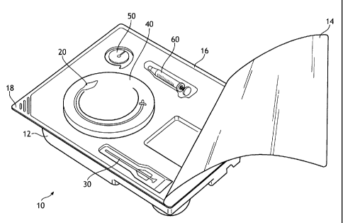
FIG. 1 depicts an illustrative view of one embodiment of the present inventive
kit for use in a
percutaneous gastrointestinal anchoring procedure.
FIG. 2 depicts an illustrative view of the anchor of the FIG. I kit in greater
detail.
FIG. 3 depicts an illustrative view of the introducer of the FIG. I kit in
greater detail.
FIG. 4 depicts an illustrative view of an alternative embodiment of the FIG. 3
introducer.
FIG. 5 depicts an illustrative view of the guide of the FIG. 1 kit in greater
detail.
FIG. 6 depicts an illustrative view of an alternative embodiment of the FIG. 5
guide.
FIG. 7 depicts an illustrative view of the retainer of the FIG. 1 kit in
greater detail.
FIG. 8 depicts an illustrative view of an alternative embodiment of the FIG. 7
retainer.
FIG. 9 depicts an illustrative view of the introducer of the FIG. 1 kit at a
point in time when
the anchor is in place in the procedure.
DETAILED DESCRIPTION OF THE PRESENT INVENTION
Reference will now be made in detail to embodiments of the invention, one or
more
examples of which are illustrated in the figures. The embodiments are provided
by way of
explanation of the invention, and not meant as a. limitation of the invention.
For example,
features illustrated or described as part of one embodiment may be used with
another embodiment to
yield still a different embodiment. The scope of the claims should not be
limited by the embodiments
set out herein but should be given the broadest interpretation consistent with
the description as a
whole.
In response to the foregoing challenges that have been experienced by those of
skill in the
art, the present invention is directed toward a kit for performing
percutaneous
gastrointestinal anchoring of the anterior wall of the stomach to an anterior
wall of the
abdomen. Components within such a kit would enable. the incising of an
exterior surface of a
living body, the introduction of an anchoring device into the incision from
the exterior
surface through intervening tissue layers and into the stomach cavity or
gastric lumen.
Moreover, components within the kit would enable the application of a tractive
force to be
6
CA 02659347 2012-07-12
applied resulting in the anchoring of the tissue layers and the ultimate
formation of an
artificial stoma or stomas into or within the living body.
As such, an embodiment of a percutaneous gastrointestinal anchoring kit 10
according to the
invention is illustrated in the figures. The kit 10 may include a tray 12
having a plurality of
planar surfaces and a plurality of recesses that may be disposed within the
planar surfaces.
The tray 12 may be formed of any suitable material, for example the tray 12
may be molded
from a transparent or translucent substantially rigid plastic material (i.e.,
PETG). The
plurality of recesses would be adapted to hold articles or implements that are
useful in
performing the procedure. Each recess may be adapted to hold one or more
articles. Articles
found useful and placed in the recesses are discussed in greater detail below.
The recesses
may also include detents, protrusions, or the like to frictionally engage the
articles and
positively retain them within the respective recesses.
As seen in FIG. 1, a cover 14 may be positioned on the tray 12 and, in some
embodiments,
may be adhered to a relatively flat peripheral surface 16 of the tray 12. A
corner 18 of the
tray 12 may be configured so that a portion of the cover 14 is not adhered to
the corner 18.
In such an embodiment, a user may grasp the cover 14 that is positioned
adjacent to the
corner 18 to remove the cover 14 from the tray 12. The cover 14 may be
attached to the tray
by any suitable method, including adhesives, heat sealing, sonic or thermal
welding, solvents,
etc. Once all of the articles have been placed into the tray 12 and the cover
14 sealed to the
tray, the kit 10 may be subjected to ETO (ethylene oxide) gas sterilization.
For this reason,
the cover 12 is gas permeable. A suitable cover material is Tyvek , a spunbond
polyolefin,
from DuPont of Wilmington, Del. Any number of other permeable web materials
suitable
for ETO gas sterilization, such as Kraft paper-, may be used as the cover 14.
In the kit 10 depicted in FIG. 1, the following articles are contained: an
anchor 20, an
introducer 30, a guide 40, a retainer 50, and an inflator 60. Additional
articles (not shown)
any of which may be provided may include an instruction pamphlet, a surgical
drape,
ointments, swab sticks, bandages, clamps, hemostats, various needles, tape,
sterile gauze,
scalpels, and a local anesthetic.
FIG. 2 depicts the anchor 20 in greater detail. The anchor 20 is adapted for
insertion into
the stomach cavity and serves to anchor an anterior wall of the gastric lumen
to an anterior
wall of the abdomen for the purpose of drawing the two walls together into
intimate contact
so as to fuse one to the other. In one simple embodiment, the anchor 20 is
provided with a
7
CA 02659347 2012-07-12
distal end 21 and a proximal end 22. As used herein, distal refers generally
to the direction of
the patient, while proximal refers to the direction of the user. The anchor 20
is formed of a
biocompatible polymeric material configured as a hollow shaft 23 with a
ballooned region 24
at or near the distal end 21.
According to some embodiments the material selected to form the anchor 20 may
include
polyurethane (PU) , low-density polyethylene (LDPE), polyvinyl chloride (PVC),
polyamid
(PA) or polyethylene teraphthalate (PETP), These materials are biocompatible
and, when
being processed into correspondingly thin walls, are especially suited for
forming the
ballooned region 24. Copolymer admixtures for modifying the characteristics of
the material
are also possible, for example a low density polyethylene and ethylene-
vinylacetate
copolymer (LDPE-EVA), or blends of the above mentioned materials (e.g. PU with
PVC or
PU with PA) would be considered suitable for such a device. Other materials
would also be
suitable so long as they exhibit properties enabling them to be processed into
anchor
mechanisms having microthin walls which do not deform elastically to such a
degree that
they are enabled to slip through the insertion channel in the body wall.
Formation of the ballooned region 24 may be achieved by situating the shaft 23
at an
appropriate position in a suitable mold (not shown), applying heat and
expanding the heated
region of the shaft controllably, typically by inflating the heated region
within the heated
mold. This process enables the discrete region to be distended without
otherwise damaging
the shaft. Due to the controlled distention of the region forming the
ballooned region, the
wall thickness is characteristically reduced in that area. Stretching the
region during this
process serves to molecularly align the polymeric chains thus making the
product otherwise
stronger than it would be even at microthin wall thicknesses. Such techniques
would be
known and understood by those of skill in the art.
Final wall thicknesses for the ballooned region 24 are considered to be
microthin in nature,
and may range from about 25 microns down to about 3 microns whereas the shaft
wall
thicknesses may range from about 50 microns to about 150 microns. As seen in
FIG. 1, the
ballooned region 24 is not elastically distendable but is preformed and exists
in a collapsed
condition when not inflated.
During the manufacturing process for the device, the distal end 21 would be
blocked,_ sealed,
or otherwise made fluid tight. Although the distended region or ballooned
region 24 may be
situated at the distal end 21, it may alternatively be proximal to the distal
end such that the
8
CA 02659347 2012-07-12
anchor 20 at the distal end 21 terminates in a nipple or tip 25. This tip 25
may also be made
non-collapsible by the filling of the tip 25 with a potting compound such as a
polymer, for
example, silicone or the like, or another biocompatible material. This would
provide a
degree of rigidity to the distal end 21 of the anchor 20 and may be desirable
in some
embodiments.
The ballooned region 24 of the anchor 20 is adapted to be inflated and
deflated. Inflation
allows the anchor 20 to perform its function as described below whereas
deflation allows the
anchor 20 to be inserted and/or removed from the patient, also as described
below. To
enable the selectable inflation/deflation of the ballooned region 24, a
connector 26 may be
situated at or near the proximal end 22 of the anchor 20. The connector 26
would be
capable of engaging the inflator 60. Suitable connectors may include luer
fittings and the like
and are known and understood by those of skill in the art.
In some embodiments, the connector 26 may comprise a releasable one-way valve
disposed
at the proximal end 22 of the anchor 20. Appropriate valves capable of serving
in this
function are known and their incorporation into the anchor 20 would prevent
inadvertent
deflation once the inflator was removed from the connector. Such devices are
well known in
the medical field and would be understood by those having skill in the art.
These valves are
suitable for actuation by means of the inflator 60 itself. Consequently, it
would be understood
that such a valve would serve as a means to control the injection of fluids
into or the removal
of the same from the anchor 20. As would be apparent, control of the inflation
of the anchor
20 enables the user or a physician, etc., to selectively control inflation and
deflation of the
ballooned .region 24.
FIG. 3 depicts the introducer 30 in more detail. The introducer 30 is adapted
to ultimately
place and deploy the anchor 20 within the gastric lumen. In the FIG. 3
embodiment, for
example, the introducer is configured as a sheath 31 having a longitudinal
bore 32 extending
axially along its length. The anchor 20 resides within the bore 32 and is
subsequently
deployed therefrom. It should be understood that the introducer 30 may simply
consist of
the sheath 31 which must be introduced into the gastric lumen by means of an
incision
performed by the clinician with a scalpel or separate introducer needle.
However, as
depicted in this embodiment, the sheath 31 may actually be used as the
introducer needle
itself for perforating the tissue and creating a stoma into the gastric lumen
or stomach cavity.
In those instances where the sheath 31 serves as the needle, a trocar tip 33
may be desirable.
9
CA 02659347 2009-01-28
WO 2008/026085 PCT/IB2007/052055
The trocar tip would be adapted to penetrate the tissue. Depending upon the
size of the
sheath 31 in comparison to the location of the connector 26 situated on the
anchor 20,
removal of the sheath 31 from the anchor may be difficult. As such, the sheath
31 may be
longitudinally splittable along a separation line 34 and removable from the
anchor in at least
two longitudinally discrete parts 35a and 35b. A pair of wings 36 would be
provided for
grasping and initiating separation of the parts 35a and 35b. Those of skill in
the art would
understand how the separation line is formed by etching or perforating the
sheath
longitudinally along its axis.
FIG. 4 depicts an alternate version of the introducer 30. In this embodiment,
the sheath 31
contains a groove or slot 37 machined into the sheath 31. The slot 37 would be
adapted to
engage a portion of the anchor 20. In this embodiment, the anchor 20 may or
may not be
situated internal to the introducer 30 and may actually be laid alongside the
introducer 30
when it is inserted into the stomach. In this way, the introducer 30 may be
removed without
splitting the sheath 31. For example, a guide described in more detail below
may be provided
with a detent 43 depicted in FIG. 6, the detent 43 is designed to be captured
in the slot 37.
In either described embodiment, the anchor 20 should be capable of deployment
and
inflation without risk of puncture or damage. This is especially of concern in
those
embodiments having the trocar tip 33. For this purpose, the guide 40 is
provided. The guide
40 serves as a rigid or semi-rigid linkage or connection between the nipple or
tip 25 and a
point proximal the proximal end 22 of the anchor 20. The guide is adapted to
be physically
grasped at one end and manipulated by a clinician. The guide 40 would prove
useful in
pushing the ballooned region 24 out of the introducer 30 prior to inflation of
the ballooned
region 24. As such, it would be simple to ensure that the ballooned region 24
be located at a
puncture safe distance from the trocar tip 33 yet be placed close to its
ultimate location. At
that time the introducer 30 may be removed from the body and the ballooned
region 24
inflated.
The guide 40 may be made of any number of rigid or semi-rigid constructs,
including a rod,
wire, shaft, tube, or thin bar. Turning now to FIG. 5, it may be seen that the
guide 40 is
affixed at a first end 41 to the distal end 21 of the anchor 20. In many
cases, the end 41 is
embedded in a potting compound 27 contained within the distal end 21,
typically in the tip
25. A second end 42 is provided near the proximal end 22 of the anchor 20 as
stated. This
second end 42 would be accessible to a clinician even should the ballooned
region 24 of the
CA 02659347 2012-07-12
anchor 20 be situated within the body of the patient. Due to the thin walls of
the anchor 20,
even though the guide 40 is within the interior of the anchor 20 it should
still be manipulable
from the exterior of the anchor 20.
As stated, the first end 41 of the guide 40 may be bedded within the potting
compound 27
contained within an interior of the anchor 20, in many instances, the tip 25.
Although the
potting compound would not normally be accessible to the body, in most
instances it likely
would comprise a biocompatible material such as silicone. Regardless of the
material used,
the potting compound should be capable of capturing one end 41 of the guide 40
at least
with respect to a pushing force. By forming this linkage or connection, it
would be
understood that any force applied to the one end 42 of the guide 40 is
transferred to the
other end 41 without buckling. The clinician by manipulating the guide 40
could effect the
position of the ballooned region 24 within the patient.
Earlier, the guide 40 was described as being seated within a potting compound
27 and
captured at least with respect to a pushing force. That phrase is meant to
indicate that the
potting compound will encompass or otherwise contain the guide 40, enable the
guide to be
pushed into the newly created stoma, while minimizing the likelihood that the
guide will
inadvertently be pushed through the potting compound and ultimately puncture
or otherwise
breach the integrity of the distal end 21 of the anchor 20. In some
embodiments the guide 40
may be removable from the anchor 20 once the ballooned region 24 is in place.
Alternatively, the guide 40 may be made sufficiently flexible so as not to
interfere with a
clinician's ability to tie a trailing end of the shaft 23 which protrudes from
the body of the
patient For example, if the guide 40 were wire-like, in some cases it. may
remain in place and
not interfere with the tying process and may even prove useful in assisting
with the tying of
the shaft so as to be fluid tight.
The guide 40 in many embodiments, like that of FIG. 5, may be situated
internally to the
anchor 20 through the shaft 23 and as such, would extend along the length of
the anchor 20.
In such embodiments, the guide 40 would be sized so as not to completely
occlude the
inflation and deflation features of the ballooned region 24. In some
embodiments, the guide
40 would be sized such that its cross-sectional area was between about one-
third to about two-
thirds of the cross-sectional area of the inside diameter of the shaft 23.
Although many of the embodiments described place the guide 40 within the
anchor 20 and
shaft 23, this is not a requirement for any of the embodiments. In fact, as
depicted in FIG. 6,
11
CA 02659347 2009-01-28
WO 2008/026085 PCT/IB2007/052055
the guide 40 may run along an exterior surface of the anchor 20 or be placed
within a wall of
the anchor 20 itself. In any event, it should not be lost sight of that the
purpose of the guide is
to enable placement of the anchor 20 within the patient and allow manipulation
of the
ballooned region 24. By articulating or otherwise moving the guide 40 at or
near the
proximal end 22 of the anchor 20, which would be external to the patient once
the anchor 20
is in place, the articulation is transferred through the anchor 20 from the
proximal end 22 to
the distal end 21.
FIG. 7 depicts a first embodiment of the retainer 50. The retainer 50 is
provided so as to
retain the anchor 20 in position. The retainer 50 is envisioned to have
numerous possible
configurations some of which will be discussed at greater length in this
specification. In this
first embodiment, the retainer 50 may be configured as a simple disc, washer,
button, or ring.
This retainer 50 could be provided with a through-hole or slot 51 for
capturing a knot 28,
depicted in FIG. 9, formed by tying off the shaft 23. The knot 28 would seat
against an
exterior facing surface 52 of the retainer 50.
One advantage gained by the use of such a retainer is that the retainer could
be made as thin
as possible, on the order of 1 to 2 mm, and in some cases dependent upon the
material from
which it is manufactured, even thinner. A retainer of this construction would
have a very low
profile and could easily be concealed by the application of a bandage over the
skin of the
patient. This would enable the anchor 20 to be in place, performing its
function, yet not be
noticeable to the public. This may provide a beneficial effect to the health
and mental well-
being of the patient as well as enable the patient to be more active in that
little of the anchor
20 would protrude from the patient's body. Moreover, this would assist in
maintaining
sterility of the site, and may minimize the potential for inadvertent
traumatic injury to the
area.
In a second embodiment depicted in FIG. 8, a multicomponent design may be used
to
secure the anchor 20 in place. One example may utilize a base plate 53 for
seating against the
patient's body, and a lid or cap 54 secured to the cap to cover the base plate
53 as well as that
portion of the anchor 20 protruding from the body. The base plate 53 may be
configured
similarly to the FIG. 7 retainer in that it would possess a slot 51 or central
opening which
would enable the base plate to secure the shaft 23. The shaft 23 may be pulled
under tension
and wedged or otherwise secured into the base plate 53, for example, by
engaging the shaft
23 with a fixture 55 such as by passing the anchor 20 through the fixture 55
and wrapping the
12
CA 02659347 2012-07-12
shaft 23 around the fixture to secure the shaft 23 in a manner reminiscent of
tying a line to a
cleat This configuration may also be covered with a bandage as described
above, or the cap
54 may be secured over the base plate .53. The base plate 53 and cap 54
configuration may
be made to have a low profile. Such an arrangement may range in thickness from
about .5
mm to about 15 mm in dimension as measured from a position normal to the
abdomen of
the patient.
A third embodiment of the retainer 50, may be similar to that depicted in US
Patent
Publication 2006/270989.
FIG. 9 depicts the anchor 20 in place within a body 100. As may be seen the
inflator 60 is
connected to the anchor 20 at the connector 26. Due to the small size of the
anchor 20, the
inflator 60 may simply be a syringe capable of injecting into as well as
removing a fluid from
the anchor 20. Although in many instances, the fluid is air, it should be
understood that the
ballooned region 24 may be inflated and deflated upon application or removal
of other
fluids, both gaseous and liquid, including but not limited to water and
saline. In the FIG. 9
embodiment, it may be seen how the anchor 20 is used to secure the gastric
wall 101 to the
abdominal wall 102 by entering the patient's body 100 into the stomach or
gastric lumen 103
through a. stoma 104 created by the initial incision.
To better serve the purpose intended, additional desirable features may be
incorporated into
the ballooned region during the molding process which would prove useful in
the application
of the invention. For example, the ballooned region 24 may be preshaped so as
to possess
sufficiently small shoulder radii at regions 201 and 202 so that a face 203
may be created
which is relatively flat in shape. This face would create a large resting or
bearing surface to
seat with the gastric wall 101. The surface area of the face 203 working in
conjunction with
inflation of the ballooned region 24 would help minimize the likelihood of the
anchor 20
from slipping out of the stoma 104. Other desirable retention element shapes
may be created
as well, depending upon the application. For example, the overall geometry of
the ballooned
region 24 may be bullet-shaped, disc-shaped, spherical, cylindrical,
frustoconical or any other
suitable shape limited only by the purpose intended and the skill of those in
the art at
forming preshaped balloons.
13
CA 02659347 2009-01-28
WO 2008/026085 PCT/IB2007/052055
As described above in more detail, once the anchor 20 is in place, the
ballooned region 24
properly situated and inflated, in many embodiments, including that of FIG. 9,
the proximal
end 22 may simply be tied off. The reason that tying the anchor at the
proximal end would
be possible is due to the small size of the anchor and the low inflation
pressures needed to
fully inflate the anchor once it is in place. It is envisioned that the
diameter of the shaft 23 in
many embodiments may be as small as from about 0.8 mm to about to 1.5 mm, and
the
ballooned region 24 may be considered fully inflated at pressures as low as
from about 50
mbar to about 200 mbar.
Other features that may be incorporated into any of the embodiments is to
provide the
anchor 20 with a lengthening feature. This may prove useful and assist in
deployment of the
anchor from the introducer. In such an embodiment, as the ballooned region 24
is inflated,
inflation is first caused to extend the anchor longitudinally prior to any
radial expansion of
the ballooned region 24. Such a feature would enable the inflation process
itself to deploy
the ballooned region from the sheath. Once the ballooned region 24 had fully
deployed
from the introducer 30 and the likelihood of damage to the anchor 20 were
minimized, the
introducer may be withdrawn from the body in any of the fashions described
above and the
ballooned region may continue to be inflated sufficiently so as to secure the
anchor in place.
This controlled expansion may be accomplished by molding the ballooned region
in a
manner that will specifically cause it to deploy from the introducer, or by
preloading the
anchor within the introducer so that it will do the same. One possible
technique which may
be used is to preload the introducer with the anchor, but to twist the anchor
torsionally
during the loading process and bunch up a portion of the anchor within the
introducer. The
twist would occlude the passage of the inflation fluid but would cause the
anchor to move
until such time as the twist were to clear the introducer. At that time, the
anchor would
untwist allowing the ballooned region to expand. Obviously folding the anchor
without
twisting may be made to accomplish the same effect.
Due to the controllable collapsibility of the anchor 20 it would be more
amenable to
atraumatic removal from the stoma than are prior art devices. This is because
the present
invention does not require the significant trans-abdominal exertion typically
associated with
those prior art devices containing a rigid shaft for carrying the balloon
component. In the
prior art devices, the mechanics of the balloon member are typically altered
negatively over
time, for example, balloon members associated with the prior art are known to
stiffen and
14
CA 02659347 2012-05-14
lose their ability to retract. fully into the shaft completely. This results
in the creation of
traumatizing folds that may exacerbate healing of the stoma site upon removal
or subsequent
manipulation of the catheter. Proper selection of materials will prevent the
present invention
from exhibiting such features.
In many of these procedures, a plurality of anchors are used in close
proximity to one
another. For example, in one gastropexy procedure, often three or four anchors
are used in
conjunction with one another. Once the stomach wall and the abdominal wall are
secured to
one another, a gastrostomy tube is often placed into the stomach lumen by
making an
additional incision at a location interior to the perimeter of the plurality
of gastropexy
devices. In any event, an individual retainer may be made to have the
capability of securing
more than one anchor 20 therein. That is, a single retainer may be used to
secure two or
more of the devices described above, so long as the devices were sufficiently
closely spaced
to one another.
As used herein and in the claims, the term "comprising" is inclusive or open-
ended and does
not exclude additional unrecited elements, compositional components, or method
steps.
While the invention has been described in detail with respect to specific
embodiments
thereof, it will be apparent to those skilled in the art that various
alterations, modifications
and other changes may be made to the invention.