Note: Descriptions are shown in the official language in which they were submitted.
CA 02660851 2009-02-13
WO 2008/022327 PCT/US2007/076232
ISOLATION DEVICES FOR THE TREATMENT OF ANEURYSMS
CROSS-REFERENCE TO RELATED APPLICATIONS
[00(!1] This application is a non-pi=ovisional of U.S. Provisional Application
No.
60/822,745 filed on August 17, 2006 entitled ISOLATION DEVICES FOR THE
TREATMENT OF ANEURYSMS. The entirety of which is hereby incorporated
by reference.
BACKGROUND OF-THE INVENTION
[0002] The tetm aneurysm refers to any localized widening or outpouching of an
artery, a vein, or the heart. All aneurysms are potentially dangerous since
die wall of
the dilated portion of the involved vessel can become weakened and may
possibly
rupture. One of the most common types of aneurysms involve the aorta, the
large
vessel that carries oxygen- containing blood away from the heart. In
particular,
aneurysms most commonly develop in the abdominal portion of the aorta and are
designated abdominal aortic aneurysms (AAA). Abdominal aoi-tic aneurysms are
most
common in men over the age of 60.
[00031 There are approximately 40,000 patients undergoing elective repair of
abdominal aortic aneurysm in the United States each year. In spite of that,
approximately 15,000 patients die from ruptured aneurysm, making aneurysm i-
upture
the 13th leading cause of death in the United States each year. This cause of
premature
death is entirely preventable providing that patients with abdominal aortic
aneurysm
can be diagnosed prior to rupture and undergo safe elective repair of the
abdominal
aortic aneurysm. Elective repair of abdominal aortic aneurysm has matured over
the
45-year interval since the first direct surgical repair of abdominal aortic
aneurysm was
performed. Conventional open surgical repair of abdominal aortic aneurysm has
often
been replaced by endovascular repair which involves a minimally invasive
technique.
Endovascular repair of abdominal aortic aneurysm utilizes access to the
vascular
system, through the femoral artery. to place a graft of appropriate design in
the
abdominal aorta in order to remove the aneurysm from the pathway of bloodflow
and
thus reduce the risk of rupture.
-1-
CA 02660851 2009-02-13
WO 2008/022327 PCT/US2007/076232
[0004] Another type of aneurysm is a brain aneurysm. Brain aneurysms are
widened areas of arteries or veins within the brain itself. These may be
caused by head
injury, an inherited (congenital) malformation of the vessels, high blood
pressure, or
atherosclerosis. A common type of brain aneurysm is known as a berry aneurysm.
Berry aneurysms are small, berry- shaped outpouchings of the main arteries
that
supply the brain and are particularly dangerous since they are susceptible to
rupture,
leading to often fatal bleeding within the brain. Brain aneurysms can occur at
any age
but are more common in adults than in children.
[0005] Currently, a variety of inethods are used to treat brain aneurysms.
Neuroradiological (catheter-based or endovascular) nonsurgical procedures
include: (i)
placement of metallic (e.g., titanium) microcoils or a "glue" (or similar
composite) in
the lumen of the brain aneurysm (in order to slow the flow of blood in the
lumen,
encouraging the aneurysm to clot off (be excluded) from the main artery and
hopefully
shrink; (ii) placement of a balloon with or without microcoils in the parent
artery
feeding the brain aneurysm (again, with the intention of stopping the flow of
blood
into the brain aneurysm lumen, encouraging it to clot off and hopefully
sluink); (iii)
insertion of a stent across the aneurysmal part of the artery to effectively
cut off blood
supply to the brain aneurysm, or to allow coiling through openings in the
stent, without
stopping blood flow across the open stent; and (iv) a combination of the
previous three
procedures. These procedures provide many advantages including allowing access
to
aneurysms that are difficult to access surgically.
[0006] However, there are still many deficiencies in these treatments. Covered
stents clesigned to cover aneurysms face the challenge of effectively covering
the
aneurysm while not occluding nearby blood vessels. If the covering is too
long, the
nearby blood vessels may be occluded creating additional potential hai-m for
the
patient. And, conventional stents, both covered and uncovered, have difficulty
targeting aneurysms located at a bifurcation or trifurcation. A berry aneurysm
located
at a bifurcation is illustrated in Fig. 1. The aneurysm A is located near the
end of a
trunk T, between two distal branches B. Blood flowing through the trunk T
continues
through the branches B but also flows into'the aneurysm A, creating pressures
and
accumulation which may lead to nipture. Typically, such aneurysms are accessed
via
the trunk T creating difficulty accessing both distal branches B. Current
attempts
utilize bifurcated stents with multiple arms and multiple wires to traverse
the blood
vessels resulting in very complex systems. Consequently, improved devices are
-2-
CA 02660851 2009-02-13
WO 2008/022327 PCT/US2007/076232
desired to isolate aneurysms, particularly at bifurcations, while maintaining
adequate
blood flow tlirough nearby vessels. These devices should be relatively easy to
produce,
deliver to a desired target area, and maintain position in a desired
orientation so as to
occlude flow in some aspect while allowing flow in others. At least some of
these
objectives will be met by the present invention.
[0007] In the case of stented abdominal aneurysnis, at least 30% of such
stented
abdominal aortic aneurysms have endoleaks. Fig. 2 illustrates an abdominal
aortic
aneurysm AAA having a stent 2 placed therein to isolate the aneurysm AAA.
Endoleaks E are shown extending from the aneurysm AAA. Many of these endoleaks
E are caused by collateral flow from the mesenteric (3-4 mm) arteries and the
lunibar
(2-3 mm) arteries. In some cases, though less commonly, such endoleaks are
caused by
collateral flow from the renal (5-6 mm) arteries. Such endoleaks E allow blood
to flow
into the aneuiysm increasing the risk of rupture. Consequently, improved
devices are
desired to isolate such aneurysms while reducing the incidence of endoleaks.
At least
some of these objectives will be met by the present invention.
SUMMARY OF THE INVENTION
[0008] The description, objects and advantages of the present invention will
become apparent from the detailed description to follow, together with the
accompanying drawings.
BRIEF DESCRIPTION OF THE DRAWINGS
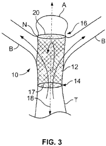
[0009] Fig. I illustrates a berry aneurysm located at a bifurcation of a blood
vessel.
[0010] Fig. 2 illustrates an abdominal aortic aneurysm having a conventional
stent
placed therein.
[0011] Fig. 3 illustrates an embodiment of an isolation device of the present
invention having an occluder.
[0012] Fig. 4 illustrates an isolation device having the form of a coil.
[00131 Figs. 5A-5B illustrate an isolation device constructed from a sheet.
[0014] Fig. 6 illustrates an isolation device wherein the occluder comprises a
diverter.
[0015] Fig. 7 illustrates an isolation device having a conical shape.
-3-
CA 02660851 2009-02-13
WO 2008/022327 PCT/US2007/076232
[0016] Fig. 8 illustrates an isolation device having a body configured for
positioning within a neck of an aneurysm.
[0017] Fig. 9 illustrates an embodiment of an isolation device having a sack
which
may extend into the aneurysm.
[0018] Fig. 10 illustrates an isolation device having a portion constructed so
as to
anchor within the trunk of the blood vessel.
[0019] Fig. 11 illustrates an embodiment of an isolation device having an
occluder
comprising struts.
[0020] Figs. 12-13 illustrate isolation devices comprising a body having a
single
end.
[0021] Figs. 14-15 illustrate isolation devices comprising a body having a
ball
shape.
100221 Fig. 16A- 16C illustrate a method of constructing a ball shaped
isolation
device.
[0023] Fig. 17A-17B illustrate a ball shaped isolation device having
articulating
stY-uts.
[0024] Figs. 18A-18C illustrate a ball shaped isolation device formed from
individual coils.
100251 Figs. 19A- 19C illustrate a ball shaped isolation device formed from
individual coils including a cover.
[0026] Figs. 20A-20C illustrate a method of delivery of the isolation device
of
Figs. 18A-18C.
[0027] Fig. 21 illustrates an abdominal aortic aneurysm having endoleaks
occluded
by isolation devices of the present invention.
[00281 Figs. 22A-22C illustrates an isolation device of the present invention
having an occluder.
[0029] Figs. 23A-23C illustrates an isolation device having a body in the form
of a
coil.
[0030] Figs. 24A-24C illustrate an isolation device constructed from a sheet.
[0031] Fig. 25 illustrates an isolation device having an occluder comprising
fibers.
[0032] Fig. 26 illustrates an isolation device having an occluder comprising a
biocompatible filler.
[0033] Figs. 27A-27B illustrate an isolation device having an occluder
comprising
a sack.
-4-
CA 02660851 2009-02-13
WO 2008/022327 PCT/US2007/076232
100341 Figs. 28A-28B illustrate an isolation device having an occluder
comprising
a valve.
[0035] Figs. 29A-29C illustrate an isolation device having an occluder
comprising
a flap.
100361 Figs. 30, 31, 32 illustrate various embodiments of isolation devices
having
a conical shape.
[0037] Fig. 33A-33B illustrate an isolation device having a conical shape and
an
occluder coniprising a flap.
[0038] Fig. 34A-34B illustrate an isolation device comprising a pair of
conical
shaped bodies.
100391 Fig. 35 illustrates a variety of niethods of incorporating radiopaque
material
into the body of an isolation device.
100401 Fig. 36 illustrates a method of joining two types of material.
[0041] Fig 37A-37B illustrates a push-style delivery system.
100421 Fig. 38 illustrates a pull-style delivery systeni.
[0043] Fig. 39A-39C illustrates a sheath-style delivery system.
[0044] Fig. 40A-40C illustrate a balloon expandable delivery system.
[0045] Fig. 41A-41B illustrate an isolation device comprising a shape memory
element coupled with a portion of material.
[0046] Fig. 42A-42D illustrate an isolation device comprising a coil having a
polymeric covering.
DETAILED DESCRIPTION OF THE INVENTION
Devices for Treatment of Berry Aneurysms
[0047] A variety of isolation devices are provided for treating berry
aneurysms,
particularly berry aneurysms located at bifurcations or other branched
vessels. An
embodiment of such an isolation device is illustrated in Fig. 3. Here, the
isolation
device 10 comprises a body 12 having a first end 14, a second end 16 and a
lumen 17
extending therethrough along a longitudinal axis 18. The isolation device 10
also
includes an occluder 20 which occludes blood flow in at least one direction.
In this
embodiment, the occluder 20 is located near the second end 16 occluding blood
flow
along the longitudinal axis 14, so as to act as an axial occluder, and
diverting flow
away from the longitudinal axis 14.
-5-
CA 02660851 2009-02-13
WO 2008/022327 PCT/US2007/076232
[0048] The body 12 may have any suitable shape or design, such as a
cylindrical
shape as shown. Further, the body 12 may be comprised of any suitable
construction,
such as braid, mesh, lattice, coil, struts or other constri-uction. The body
12 shown in
Fig. 3 has a wire braid construction. Likewise, the occluder 20 may have any
suitable
shape, design or construction. For example, the occluder 20 may be comprised
of a
solid sheet, a. sheet having openings, a mesh, a lattice, struts, thi-eads,
fibers, filaments,
a biocompatible filler or adhesive, or other suitable material. The occluder
20 shown in
Fig. 3 comprises a solid sheet extending across the second end 16.
10049] The isolation device 10 is positioned within the tiunk T of the
bifurcated
blood vessel so that the second end 16 is disposed near the aneurysm A,
preferably
within, against or near a neck N of the aneurysm A. Thus, blood flowing
through the
trunk T is able to flow tlu=ough the device 10, entering through the first end
14 and
exiting radially through the sides of the body 12 to the distal branches B.
Flow is
resisted through the second end 16 by the occluder 20. Thus, the aneurysni A
is
isolated from the blood vessel without restricting flow through the trunk T or
distal
branches B. In some embodiments, the body 12 has varied construction along its
length to facilitate radial flow through the sides of the body 12. For
example, the braid,
mesh or lattice may have larger openings in specific areas to facilitate flow
theretlu=ough.
100501 Fig. 4 illustrates another embodiment of an isolation device 10. Here
the
body 12 has the form of a coil. Again the body 12 has a first end 14 and a
second end
16. The device 10 also includes an occluder 20 located near the second end 16.
Thus,
flow entering the first end 14 is resisted through the second end 16 by the
occluder 20
but is allowed to flow radially outwardly through the sides of the body 12.
Again, the
body 12 may have varied constniction along its length to facilitate radial
flow through
the sides of the body 12. For example, the pitch of the coil may be increased
in specific
areas to facilitate flow therethrough.
[0051] Figs. 5A-5B illustrate an isolation device 10 constructed from a sheet
22.
Fig. 5A illustrates a sheet 22 having at least one opening 24. The sheet 22 is
joined,
coupled or overlapped along an edge 26 so as to form the body 12 of the device
10
having a cylindrical shape. Fig. 5B illustrates the device 10 having a body 12
constructed as in Fig. 5A and an occluder 20 disposed near the second end 16.
Thus,
blood flowing through the first end 14 is resisted at the second end 16 by the
occluder
20 but is allowed to flow radially outwardly through the at least one opening
24.
-6-
CA 02660851 2009-02-13
WO 2008/022327 PCT/US2007/076232
[0052] Referring to Fig. 6, in some embodiments the occluder comprises a
diverter
30. The diverter 30 diverts flow, typically within the body 12 of the
isolation device 10
so as to redirect flow from along the longitudinal axis to a radially
outwardly direction.
The diverter 30 illustrated in Fig. 6 has a conical shape wherein a tip 32 of
the conical
diverter 30 extends into the body 12 along the longitudinal axis 18 and faces
the first
end 14. Thus, blood flow entering the first end 14 is diverted radially
outwardly
through the sides of the body 12 to the distal branches B by the diverter 30.
Consequently, blood does not enter the aneurysm A. It may be appreciated that
the
diverter 30 may have any suitable shape including flat, stepped, curved,
radiused,
convex and concave, to name a few.
[0053] In some embodiments, as shown in Fig. 7, the body 12 of the isolation
device 10 acts as a diverter. Here, the body 12 has a base 34 is positioned
withi.n,
against or near the neck N of the aneurysm A and a conical tip 32 facing the
trunk T.
Thus, blood flowing through the trunk T is diverted into the distal branches
B.
[0054] Fig. 8 illustrates an embodiment of an isolation device 10 comprising a
body 12 having a first end 14, a second end 16 and a longitudinal axis 18
therethrough.
The body 12 is configured so that the first end 14 resides outside of the neck
N of the
aneurysm A and is secured against the neck N, such as by virtue of a wider
dimension
or lip which is prevented from passing tlu-ough the neck N. The body 12
extends
through the neck N so that the second end 16 resides within the aneurysm A. An
occluder 20 may be disposed near the second end 16. as shown, near the first
end 14 or
anywhere therebetween to resist blood flov.: from entering the aneurysm A.
Thus,
blood flowing through the trunk T of the vessel freely flows to the distal
branches B
without significantly passing through the isolation device 10.
[0055] Fig. 9 illusti-ates an embodiment of an isolation device 10 comprising
a
body 12 having a first end 14, a second end 16 and a longitudinal axis 18
therethrough.
Here, the body 12 is configured similar to the embodiment of Fig. 3. However,
here
the occluder 20 coniprises a bag or sack of a flexible material which may
extend into
the aneurysm A.
[0056] Fig. 10 illustrates an embodiment of an isolation device 10 comprising
a
body 12 having a first end 14, a second end 16 and a longitudinal axis 18
therethrough.
In this embodiment, the first end 14 is constructed so as to act as an anchor
within the
trunk T. For example, the first end 14 may have a braided construction which
provides
radial force. In addition, the first end 14 may include anchors. such as
hooks, loops, or
-7-
CA 02660851 2009-02-13
WO 2008/022327 PCT/US2007/076232
spikes which engage a wall of the blood vessel. The second end 16 is
constructed so as
to atraumatically reside within, against or near the neck N of the aneurysm A.
Thus,
the second end 16 provides less radial force. The body 12 extending between
the ends
14, 16 may have any suitable construction, such as a braid, mesh, lattice,
coil, struts, to
name a few. In this embodiment, the body 12 comprises struts 38 extending
between
the ends 14, 16. Thus, blood flow entering the first end 14 may flow radially
outwardly
between the struts 38 to the distal branches B.
100571 Fig. 11 illustrates an embodiment of an isolation device 10 comprising
a
body 12 having a first end 14, a second end 16 and a longitudinal axis 18
therethrough.
Here, the body 12 is configured similar to the embodiment of Fig. 3. However,
in this
embodiment the occluder 20 comprises struts 40 extending across the second end
16.
The struts 40 have a denser configuration than the body 12 so as to reduce
flow
therethrough.
[0058] Fig. 12 illustrates an embodiment of an isolation device 10 comprising
a
body 12 having a single end 42. The end 42 is positionable within, against or
near the
neck N of the aneurysm A as shown, with the use of a guide 44. In this
embodiment,
an occluder 20 extends across the end 42 to prevent flow into the aneurysm A.
To
assist in holding the end 42 near the neck N, the end 42 may be radiofrequency
(rf)
welded to the neck N area.
100591 Fig. 13 illustrates another embodiment of an isolation device 10
comprising
a body 12 having a single end 42. Again, the end 42 is positionable within,
against or
near the neck N of the aneurysm A as shown, with the use of a guide 44. In
this
embodiment, an occluder 20 has the shape of a bag or sack extending into the
aneurysm A. Such extension into the aneurysm A may reduce any risk of
dislodgement, particularly if the occluder 20 has some rigidity. To assist in
holding the
end 42 near the neck N, the end 42 may be radiofrequency (rf) welded to the
neck N
area.
100601 Fig. 14 illustrates another embodiment of an isolation device 10. Here,
the
isolation device 10 comprises a body 12 having a ball shape which includes
round,
spherical, elliptical, oval and egg-shaped. Thus, the ball shaped body 12 may
be
disposed within the intersection of the trunk T, distal branches B and
aneurysm A. The
ball shape allows the body 12 to reside within the intersection without the
need for
anchoring within a specific vessel. Optionally, the device 10 may be slightly
oversized
within the intersection to assist in its stability and security. The body 12
may be
-8-
CA 02660851 2009-02-13
WO 2008/022327 PCT/US2007/076232
comprised of any suitable constiuction, such as braid, mesh, lattice, coil,
struts or other
construction. Blood flowing through the trunk T enters the body 12 and exits
the body
12 through to the distal branches B while flow to the aneurysm A is prevented.
This is
achieved by varying the density of the construction. For example, a body 12
constructed of mesh may have a denser mesli configuration over the aneurysm A
and a
looser mesh over the distal branches B. Optionally, the body 12 may include
openings
or apertures therethrough, such as substantially aligned with the distal
branches B or
trunk T, so as to allow access or crossing by a catheter. Further, as
illustrated in Fig.
15, the device 10 may include a cover 50 which extends over a desired portion
of the
body 12. The cover 50 may be of any suitable size, shape or material. For
example, the
cover 50 may be comprised of ePTFE and may cover a portion of the body 12
slightly
larger than the neck N of the aneurysm A. Thus, the cover 50 may assist in
preventing
flow into the aneurysm A.
100611 Figs. 16A- 16C illustrate a method of constructing the isolation device
10
of Fig. 14. Fig. 16A illustrates a mesh sheet 52 comprised of a suitable
material, such
as nitinol wire. The sheet 52 is then formed into a ball-shaped body 12 by
wrapping
the sheet 52 so that the ends substantially align and the ends are trimmed and
laser
welded, as illustrated in Fig. 16B. The ball-shaped body 12 may then be
compressed,
as illustrated in Fig. 16C, for delivery through a delivery catheter.
[00621 In some embodiments, the ball-shaped body 12 of the isolation device 10
is
comprised of articulating struts 54, as illustrated in Figs. 17A-17B. Fig. 17A
shows the
body 12 comprised of such struts 54 and Fig. 17B shows an expanded view of a
portion of the body 12 showing the individual struts 54 connected by joints 56
which
allow the struts 54 to rotate in relation to each other. Such articulating
struts 54 may
allow the use of more rigid materials since the struts 54 may rotate in
relation to each
other to facilitate compression of the device 10 for delivery. Alternatively,
the struts 54
may bend or angulate to facilitate compression.
100631 In some enlbodiments, the isolation device 10 is comprised of separate
parts that togetlier form the isolation device 10. For example, referring to
Figs. 18A-
18C. an isolation device 10 having a ball-shaped body 12 may be formed from
individual coils. Fig. 18A illustrates a first coil 60 positioned horizontally
and Fig. 18B
illustrates a second coil 62 positioned vertically. In this embodiment, each
of the coils
60, 62 vary in diameter, varying from smaller near its ends and larger near
its center.
Fig. 18C illustrates the combination of the first coil 60 and second coil 62
foi-niing a
-9-
CA 02660851 2009-02-13
WO 2008/022327 PCT/US2007/076232
ball-shaped body 12. By positioning the coils 60. 62 substantially
perpendicularly to
each other, the larger center of the first coil 60 engages the smaller ends of
the second
coil 62 and vice versa. Thus, a ball-shape is formed. In some embodiments,
each turn
the first coil 60 overlaps the previous turn of the second coil 62, creating
overlapping
and underlapping coil turns amongst the coils 60. 62.
[0064] Similarly, Figs. 19A- 19C illustrate an isolation device 10 formed from
individual coils, wherein the device 10 includes a cover 50. Fig. 19A
illustrates a first
coi164 positioned horizontally and Fig. 19B illustrates a second coi166
positioned
vertically, wherein the second coil 66 includes a cover 50. In this
embodiment, the
cover 50 covers one end of the second coi166. However, it may be appreciated
that the
cover 50 may cover any portion of the second coil 66. Likewise, more than one
cover
50 may be present. and one or more covers 50 may be alternatively or
additionally
cover portions of the first coi164. In this embodiment, each of the coils 64,
66 vary in
diameter, varying from smaller near its ends and larger near its center. Fig.
19C
illustrates the combination of the first coi164 and second coil 66 forming a
ball-shaped
body 12. By positioning the coils 64, 66 perpendicularly to each other, the
larger
center of the first coil 60 engages the smaller ends and cover 50 of the
second coi162
and vice versa. Thus, a ball-shape is formed includinQ a cover 50. Further,
the cover 50
may be held in place by sandwiching between the first and second coils 64, 66.
[0065] In some embodiments, an isolation device 10 comprised of separate parts
is
formed into its desired shape, such as a ball-shape, and then delivered to a
target
location with the body. However, in other embodiments, the separate parts are
delivered individually to the target location form the isolation device 10 in
vivo. For
example, Figs. 20A-20C illustrate such delivery of the isolation device 10.
Fig. 20A
illustrates delivery of the first coil 60 (of Fig. 18A) to a target location
within a
bifurcated blood vessel BV near an aneurysm A. The coi160 is delivered from a
delivery catheter 68 and positioned near the aneurysm A. Fig. 20B illustrates
delivery
of the second coi162 (of Fig. 18B) to the target location. The second coi162
is
delivered from the delivery catheter 68 (or from another delivery catheter or
device) in
an orientation so as to combine with the first coil 60 forming an isolation
device 10. In
this embodiment, the second coil 62 is delivered at a substantially
perpendicular angle
to the first coil 60 forming a ball-shaped body 12, as illustrated in Fig.
20C.
Devices for Occluding Endoleaks of Aneurysms
-10-
CA 02660851 2009-02-13
WO 2008/022327 PCT/US2007/076232
[0066] A variety of isolation devices are provided for treating endoleaks of
aneurysms. particularly abdominal aortic aneurysms. It may be appreciated that
such
isolation devices may also be used to occlude any blood vessels within the
body or any
luminal anatomy. Fig. 21 illustrates an abdominal aortic aneurysm AAA having
endoleaks E. Isolation devices 10 of the present invention are shown
positioned within
the endoleaks E so as to occlude the endoleaks E.
100671 Fig. 22A illustrates an isolation device 10 comprising a body 70 having
a
first end 72, a second end 74 and a hunen 75 having a longitudinal axis 76
extending
therethrough. The isolation device 10 also includes an occluder 78 which
occludes
blood flow in at least one direction. In this embodiment, the occluder 78 is
located near
the first end 72 occluding blood flow through the lumen 75 along the
longitudinal axis
76 so as to act as an axial occluder. In some embodiments, the isolation
device of Fig.
22A has similarities to the isolation device of Fig. 3. However, in this
embodiment, the
isolation device 10 is configured to be positioned within an endoleak E so as
to
occlude blood flow in an axial direction.
[0068] The body 70 may have any suitable shape or design. such as a
cylindrical
shape as shown. Further, the body 70 may be comprised of any suitable
construction,
such as braid, mesh, lattice, coil, struts or other construction. The body 70
sllown in
Fig. 22A has a wire braid construction. Likewise, the occluder 78 may have any
suitable shape, design or construction. For example, the occluder 78 may be
comprised
of a solid sheet, a sheet having openings, a mesh, a lattice, struts, threads,
fibers,
filaments, a biocompatible filler or adhesive, or other suitable material. The
occluder
78 shown in Fig. 22A comprises a solid sheet extending across the first end
72. It may
be appreciated that the occluder 78 may alternatively extend across the lumen
75 at
any position between the ends 72, 74, as illustrated in Fig. 22B. Or, the
occluder 78
may encase or encapsulate the body 70, as illustrated in Fig. 22C. In some
embodiments, the sheet is comprised of ePTFE and is sandwiched between
portions of
the body 70 or is bound to a layer of the body 70.
[00691 Figs. 23A-23C illustrate another embodiment of an isolation device 10.
Here the body 70 has the form of a coil. Again the body 70 has a first end 72
and a
second end 74. The device 10 also includes an occluder 78 located near the
first end
72. In some embodiments, the isolation device of Fig. 23A has similarities to
the
isolation device of Fig. 4. However, in this embodiment, the isolation device
10 is
configur-ed to be positioned within an endoleak E so as to occlude blood flow
in an
-11-
CA 02660851 2009-02-13
WO 2008/022327 PCT/US2007/076232
axial direction. It niay be appreciated that the occluder 78 inay
alternatively extend
across the coil at any position between the ends 72, 74. as illustrated in
Fig. 23B. Or,
the occluder 78 n-iay encase the body 70, as illustrated in Fig. 23C.
[0070) Figs. 24A-24C illustrate an isolation device 10 constructed from a
sheet 80.
The sheet 22 is joined, coupled or overlapped along an edge 82 so as to fonn
the body
70 of the device 10 having a cylindrical shape. Fig. 24A illustrates the
device 10
having an occluder 78 disposed near the first end 72. It may be appreciated
that the
occluder 78 may alternatively extend across the device 10 at any position
between the
ends 72, 74, as illustrated in Fig. 24B. Or. the occluder 78 may encase the
body 70, as
illustrated in Fig. 24C.
100711 As inentioned, the body 70 may be comprised of any suitable
construction,
such as braid, mesh, lattice, coil, struts or other construction, and the
occluder 78 may
have any suitable sliape. design or construction, such as a solid sheet, a
sheet having
openings, a mesh, a lattice, stiuts, threads, fibers, filaments, a
biocompatible filler or
adhesive, or other suitable material. Fig. 25 illustrates an occluder 78
comprising fibers
86 that extend across the lumen 75 of the body 70. The fibers 86 may oilly
partially
cover the luinen 75, however such coverage may be sufficient to occlude blood
flow
therethrough. Likewise. the fibers 86 may initiate and encourage thrombus
formation
to form a more complete seal at a later time. Fig. 26 illustrates an occluder
78
comprising a biocompatible filler 88.
[00721 Figs. 27A-27B illustrate an isolation device 10 having an occluder 78
comprising a sack 90. The sack 90 may be comprised of any flexible material
such as
ePTFE, urethane or other elastic or polymeric material. Fig. 27A illustrates
the sack 90
extending beyond the second end 74 of the device 10. Such a configuration
would be
typical in situations wherein blood would enter the lumen 75 tlu=ough the
first end 72
moving toward the second end 74. Fig. 27B illustrates the sack 90 extending
into the
lumen 75. Such a configuration would be typical in situations wlierein blood
would
enter the lumen 75 through the second end 74 moving toward the first end 72.
[0073] Figs. 28A-28B illustrate an isolation device 10 having an occluder 78
comprising a valve 96. The valve 96 typically comprises a one-way valve, such
as a
duck bill valve. Fig. 28A illustrates the valve 96 extending beyond the second
end 74
of the device 10. Such a configuration would be used to block flow of blood
which
naturally flows from the second end 74 toward the first end 72. Thus, the
valve 96
would restrict or prevent flow through the lumen 75. Fig. 28B illustrates the
valve 96
-12-
CA 02660851 2009-02-13
WO 2008/022327 PCT/US2007/076232
extending into the lumen 75. Such a configuration would be used to block flow
of
blood which naturally flows from the first end 72 toward the second end 74.
[0074] Figs. 29A-29C illustrate an isolation device 10 having an occluder 78
comprising a flap 100. Here the isolation device 10 has a body 70 constructed
from a
sheet 102 having a first edge 104 and a second edge 106. The sheet 102 is
rollable so
that the first edge 104 overlaps the second edge 106, as illustrated in Figs.
29A-29B. In
this embodiment, the flap 100 is cut or formed from the sheet 102, and the
flap 100 is
preformed so as to be biased inward toward the lumen 75. In other embodiments,
the
flap 100 is attached to the sheet 102. Referring to Fig. 29A, the sheet 102
may be
rolled so that portions of the sheet 102 near the first edge 104 overlap the
flap 100,
thereby supporting the flap 100 and resisting movement of the flap 100
inwardly. Fig.
29B provides an end view of the sheet 102 wherein the flap 100 is resisted
from
moving inwardly by the portion of the sheet near the first edge 104. In this
collapsed
configuration, the device 10 is deliverable to a taraet location in the body.
Refening to
Fig. 29C, the device 10 may then be deployed, allowing the sheet 102 to unroll
so that
the first edge 104 and second edge 106 are drawn closer together. This reveals
the flap
100 and allows inward movement of the flap 100 to occlude the lumen 75. The
flap
100 may be coated or constructed from a material that provides a good seal.
100751 In some embodiments, the isolation device 10 has a conical shaped body
70. Fig. 30 illustrates a device 10 having a body 70 formed from a sheet 102
having a
first edge 104 and a second edge 106, wherein the edges 104, 106 meet or
overlap so
that the body 70 has a conical shape with a tip 110 and a base 112. Thus, the
tip 110
forms the occluder by preventing blood flow through the device 10 when the
base 1 12
is expanded within a blood vessel. Optionally, as illustrated in Fig. 31, the
base 112
may include anchoring elements 114, such as rings, to assist in anchoring the
base 112
to the blood vessel.
[0076] In some embodiments, as illustrated in Fig. 32, the conical shaped body
70
is formed from a lattice or mesh sheet 102. In such embodiments, the tip 1 10
may act
as an occluder. However, the device 10 may include an additional occluder 78
over the
base 1 12 to assist in blockage of blood flow theretlirough. Similarly, as
illustrated in
Figs, 33A-33B, the occluder 78 may be comprised of a biased flap 100 which
extends
from the base 1 12when the body 70 is collapsed (Fig. 33A) and moves inwardly
so as
to cover the base 112 when the body 70 is expanded (Fig. 33B).
-13-
CA 02660851 2009-02-13
WO 2008/022327 PCT/US2007/076232
[0077] It may be appreciated that in some embodiments. the isolation device 10
is
comprised of a plurality of conical shaped bodies 70. Fig. 34A illustrates a
pair of
conical sliaped bodies 70 positioned within a blood vessel BV. As shown, each
body
70 has a tip 1 10 and the tips 1 10 are coupled, such as by a connector 1 16,
so that the
bases 1 12 face away from each other. Such plurality of bodies 70 may increase
the
ability of occluding the blood vessel BV. Fig. 34B illustrates alternative
positioning of
the isolation device 10 of Fig. 34A. Here, the device 10 is positioned so that
a first
conical shaped body 70' is positioned within a trunk T of the blood vessel BV
and a
second conical shaped body 70" connected directlv thereto is positioned at
least
partially outside of the trunk T, such as within a branch B of the blood
vessel BV.
Such positioning may also increase the ability of occluding the blood vessel
BV.
[0078] Each of the isolation devices 10 of the present invention may be
radiopaque
to assist in visualization during placement within a target location in the
body. Thus,
radiopaque material, such as gold, platinum, tantalum, or cobalt chromium, to
name a
few, may be incorporated into the device 10. Fig. 35 illustrates a variety of
inethods of
incorporating radiopaque material, such as deposition between sheets of
niaterials
(such as nitinol and ePTFE), deposition in cut channels in body of device,
chemical
deposition, sputtered deposition, ion deposition, weaving, and crimping, to
name a
few.
[0079] In some embodiments, it may be desired to have some components elastic
and sonie inelastic. It is often the case that these materials cannot be
easily connected.
Fig. 36 illustrates a method where two such materials can be joined by way of
a
mechanical fit and then sealed by a pressure fit of a material constraining
the surface
and keeping the dissimilar pieces locked in position relative to each other.
This is only
an example and nlany others are possible with a similar objective.
100801 A variety of delivery devices may be used to deliver the isolation
devices
of the pi-esent invention. For example, Figs. 37A-37B illustrate a push-style
delivery system. In this embodiment, the delivery system comprises a catheter
120
having a lumen 122 and a push-rod 124 extending through the lumen 122. The
isolation device 10 is loaded within the lumen 122 near the distal end of the
catheter
120. The catheter 120 is then advanced tlirough the vasculature to a target
delivery site
within a blood vessel V. The isolation device 10 is then deployed at the
target delivery
site by advancing the push-rod 124 which pushes the device 10 out of the lumen
122
and into the blood vessel V.
-14-
CA 02660851 2009-02-13
WO 2008/022327 PCT/US2007/076232
100811 Fig. 38 illustrates a pull-style delivery system. In this embodiment,
the
delivery systeni coinprises a catheter 130 having a lumen 132 and a pull
element 134
extending through the lumen 132. The isolation device 10 is loaded within the
lumen
132 near the distal end of the catheter 130 and attached to the pull element
134. The
catheter 130 is then advanced through the vasculature to a target delivery
site within a
blood vessel. The isolation device 10 is then deployed at the target delivery
site by
advancing the pull element 134 which pulls the device 10 out of the lunien 132
and
into the blood vessel V. It may be appreciated that the pull eletnent 134 inay
alternatively extend along the exterior of the catheter 130 or through a lumen
in the
wall of the catheter 130.
[00821 Figs. 39A-39C illustrate a sheath-style delivery system. In this
embodiment, the delivery system comprises a rod 140 positionable within a
sheath
142. The isolation device 10 is mountable on the rod 140 and the sheath 142 is
extendable over the isolation device 10, as illustrated in Fib. 39A. The
system is then
advanced so that the device 10 is desirably positioned with a blood vessel V.
In this
embodiment, the t-od 140 includes radiopaque markers 146 to assist in such
positioning. The sheath 142 is then retracted, as illustrated in Fig. 39B,
releasing
device 10 within the blood vessel V. Once the device 10 is deployed, as
illustrated in
Fig. 38C, the rod 140 may then be retracted leaving the device 10 in place.
This type
of delivery system may be particularly suited for delivery of devices such as
illustrated
in Figs. 27A-27B and Fi-s. 28A-28B.
[00831 Figs. 40A-40C illustrate a balloon expandable delivery system. In this
embodiment, the delivery system comprises a catheter 150 having an expandable
balloon 152 mounted near its distal end. The isolation device 10 is crimped
over the
balloon 152 as illustrated in Fig. 40A. The catheter 150 is advanceable so
that the
device 10 may be positioned at a target location within a blood vessel V. The
balloon
152 may then be expanded (Fig. 40B) which in turn expands the device 10,
securing
the device 10 within the blood vessel. In this embodiment, the device 10 has a
conical
shape wherein the tip 1 10 comprises an elastic material which allows the tip
1 10 to
recoil after delivery, as shown in Fig. 40C. This type of delivery system may
be
particularly suited for delivery of devices such as illustrated in Figs. 29A-
29C and
Figs. 33A-33B.
[0084] Figs. 4 1 A-4 I B illustrate another embodiment of an isolation device
10. In
this embodiment, the isolation device 10 comprises a shape memory element 160,
such
-15-
CA 02660851 2009-02-13
WO 2008/022327 PCT/US2007/076232
as a wire or ribbon comprised of nitinol, coupled with a portion of material
162, such
as a sheet or ribbon comprised of ePTFE. The shape memory element 160 is
attached
the portion of material 162, such as along an edge as shown in Fig. 41A. When
the
shape memory element 160 has a linear configuration, the device 10 may be
loaded
into a lumen of a delivery catheter or delivery device for advancement to a
target
location within a blood vessel. The shape memory element 160 may then change
shapes to a curled, coiled, or random shape, causing the isolation device 10
to form a
ball-shape as illustrated in Fig. 41B. The ball-shape tlius occludes flow
through the
blood vessel at the target location.
[0085] Figs. 42A-42D illustrate another embodiment of an isolation device 10.
In
this embodunent, the isolation device 10 comprises a coil 170 having a heat
activated
covering 172. The coil 170 may comprise a conventional embolic coil, such as a
Guglielmi Detachable Coil (GDC). A GDC is a platinum alloy or similar coil,
which
has a natural tendency or a memory effect, allowing it to fonn a coil of a
given radius
and coil thickness and softness. GDC coils are manufactured in a variety of
sizes from
2mm in diameter or more, and in different lengths. Further, conventional GDCs
are
available in a variety of coil thicknesses, including 0.0 10" and 0.0 18", and
two
stiffnesses (soft and regular). It may be appreciated that the coil 170 may
alternatively
be comprised of other types, sizes and materials.
[0086] Fig. 42B provides a cross-sectional view of the coil 170 having the
covering 172. Example coverings 172 include thermoplastic materials and
thermoplastic elastomers, such as polyurethane, polyester, Pebax B, nylon,
pellathane,
TecoflexB and TecothaneB. Example coverings 172 also include heat activated
adhesives. One or more coils 170 are then delivered to a blood vessel, such as
an
endoleak. Once delivered, the coil 170 is heated up, allowing the covering 172
to reach
a glass-transition temperature and turning it into a soft semi-gelatinous
consistency.
Upon cooling, the covering 172 reforms its shape, acting as a glue or binding
agent. A
single coil 170 which has been heated and cooled will hold its three-
dimensional shape
as shown in Fig. 42C, making it more stable for occluding the blood vessel.
[0087] Such coils 170 may also be used to treat berry aneurysm. In sucli
instances,
a catheter is advanced into the blood vessel supplying the aneurysm. A second
smaller
catheter called a microcathetei- is then advanced through the catheter to the
aneurysm.
The coils 170 are placed through the microcatheter into the aneurysm until the
aneurysm is satisfactorily filled. Multiple coils 170 packed into an aneurysm
A (Fig.
-16-
CA 02660851 2009-02-13
WO 2008/022327 PCT/US2007/076232
42D) will become "locked together as the covering 172 binds to the neighboring
coil.
Each coil 170 is typically heated as it is delivered, such as by using the
delivery
catheter to input radiofrequency energy. Alternatively, all of the coils 170
could be
heated at the same time. such as with a secondary radiofrequency induction
catheter, or
with an external MRI field.
[0088] The thickness of the covering 172 could be adjusted for optimum
performance. The coils shown in Fig. 42D are locked together by the heated and
cooled covering, causing the coils to resist further re-paclcing or
remodeling.
Typically, conventional GDC coils (without such a polynier-ic covering) are
not stable
within the aneurysm and can rearrange shape, position and packing density
leading to
reduce effectiveness. In some instances, intervention in needed to add
additional coils
to improve packing. However, the covering 172 of the present invention resists
further
re-packing or remodeling. The covering 172 could also aid in reducing the fi-
ee space
between coils 170.
[0089] Although the foregoing invention has been described in some detail by
way of illustration and example, for purposes of clarity of understanding, it
will be
obvious that various alteinatives, modifications and equivalents may be used
and the
above description should not be taken as limiting in scope of the invention
which is
defmed by the appended.
-17-