Note: Descriptions are shown in the official language in which they were submitted.
CA 02662023 2012-05-23
WIRELESS TAG AND AUXILIARY DEVICE FOR USE WITH HOME
MONITORING UNIT FOR TRACKING INDIVIDUALS OR OBJECTS
FIELD OF THE INVENTION:
100011 The present invention relates to systems which provide location
tracking and monitoring of a portable tracking device or "tag" that is affixed
to an
individual or other object, and in which the device periodically communicates
data to
a remote monitoring station. More specifically, the present invention relates
to the
implementation of limited RF capability in the tag and another system device,
hereinafter "auxiliary device" to provide improved system features and
functions.
BACKGROUND OF THE INVENTION:
[0003] Electronic location monitoring and tracking of individuals or objects
can
be carried out in a number of ways. Determining the location of the tag can be
provided using well-known techniques, such as GPS, cellular triangulation, or
a
combination of both. Further, in certain system applications, tamper detection
capability and the ability to generate alarms upon detecting tampering or upon
other
conditions may be included. There are variants of electronic location
monitoring and
tracking systems. For example, some systems rely upon electronic monitoring at
a
fixed located such as the individual's home or place of employment. These
systems
can rely upon a land line telephone link and are commonly known as house
arrest
systems. These systems utilize a transmitter worn by the individual and a
stationary
receiver located at the monitoring location.
-1-
CA 02662023 2012-05-23
When the individual is an "offender", i.e., a person under a government-
supervised
program, the transmitter incorporates tamper-detection capabilities and upon
such
detection may transmit an alarm. The wom transmitter transmits a signal a
short
distance to the receiver located at the monitoring location. The receiver
communicates
with a central monitoring service over standard telephone lines. The tracking
system of
this type is limited in that it can only provide an indication of the presence
or absence of
the individual at the monitored location at a given time. This type of system
cannot offer
location information if the individual leaves the monitored location.
[0004] US Patent Nos. 5,867,103 and 6,160,481 disclose a
system which provides for a locational tracking of a plurality
of monitored persons. The system has a portable monitoring device for each of
the
monitored persons. Each portable monitoring device has means to secure the
device to
a respective monitored person and may include means to detect tampering with
the
secured device for offender applications. Additionally, each portable
monitoring device
has means to receive a distinct signal generated by a detached sending unit.
Each
portable monitoring device also has means to transmit a signal containing
data. The
system further has means to acquire the signal containing data transmitted by
each
respective portable monitoring device. The system has means to determine a
positional
location of the portable monitoring device based, at least in part, upon the
distinct signal
received by the portable monitoring device. The system has means to mark, at
least
within a range of time references, when the positional location reference was
determined in the form of an occurrence reference. The system has means to
store, for
archival retention within a locational tracking database, at least a series of
the position
references and associative occurrence references of each portable monitoring
devices
of the tracking system.
[0005] US Patent No. 6,774,797 discloses a one-piece
lightweight waterproof personal tracking tag which is attached to
an individual using either a tamper detection strap or other suitable means of
connection. The tag communicates with a global positioning satellite network
and a
wireless network to obtain geographic location information and to exchange
data with a
centralized data system. The tag monitors the location of the wearer of the
tag,
-2-
CA 02662023 2009-02-26
WO 2008/027985 PCT/US2007/077142
compares the monitored location to a database of acceptable and unacceptable
location
and time parameters and provides updates to a centralized database system, the
monitoring station, and receives downloads and updates from the system.
[0006] For locational tracking and monitoring of one or more individuals, each
having an individual set of allowed geographic and temporal restrictions, the
system
must maintain an extensive database of individuals and corresponding
restrictions. In
such applications, the tag preferably incorporates a microcontroller, flash
memory, a
cellular modem, a GPS receiver, tamper detection, and a rechargeable battery
in a
single lightweight unit. One or more individuals are provided with a tracking
tag. Each of
the tags reports into the monitoring station on a periodic basis. The
reporting basis can
be on a predetermined schedule and/or can be based upon detection of a
violation or
other reportable condition detected by the tag itself. Information reporting
by the various
tags is recorded and analyzed at the monitoring station by the data tracking
system to
determine if individual violations have occurred. The centralized data
tracking system
can then take an appropriate action to notify, respond to and/or correct the
noted
violation.
[0007] The tag's ability to properly function is limited by the capabilities
of the
tag's battery and the ability of the tag's circuitry to function properly in
different
locations. Current GPS based tracking systems, for example, will not function
properly
when GPS reception becomes impaired or is lost. In addition, the demands of
system
applications place increasing power loads and operating time requirements on
the tag's
batteries. Both of these shortcomings can be especially acute in offender
tracking and
monitoring applications where loss of offender locational monitoring is
unacceptable. It
would be desirable to provide a mechanism for efficiently extending the range
of such
GPS tracking systems particularly in areas in which GPS reception is impaired.
It would
also be desirable to provide such extended coverage where no action is
required by the
offender. It would also be desirable to provide such expanded coverage where
removal
of the offender's GPS device is not required.
-3-
CA 02662023 2012-05-23
SUMMARY OF THE INVENTION
[0007a] Certain exemplary embodiments can provide a location tracking device
for use with an auxiliary device, the tracking device comprising: position
determining
circuitry and first short range wireless circuitry that communicates position
data
representative of the location of the tracking device to an auxiliary device
wherein the
auxiliary device has an ID along with second short range wireless circuitry
that
communicates this ID to the tracking device and long range communications
circuitry
that communicates the position data to a remote location, and wherein the
location
tracking device has first and second operational modes and switches between
these
operational modes, and wherein the decision to switch operational modes is at
least
partially based on the auxiliary device ID; wherein when in the first
operating mode,
the tracking device over time stores and accumulates in the memory multiple
instances of the generated location data from the location circuitry, but does
not
transmit either a current location of the one-piece monitoring device or any
stored
location in the memory; wherein when in the second operating mode: the one-
piece
monitoring device initially determines its location, becomes wirelessly
tethered to the
auxiliary mode, and subsequently reduces the operations of the location
circuitry; and
the combination of the initially determined location and the tethered status
of the
monitoring device to the auxiliary device replace location determinations for
at least
portions of the second operating mode; wherein in association with the one-
piece
monitoring device transitioning from the first operating mode to the second
operating
mode: the monitoring device batch transmits from the memory to the auxiliary
device
via at least the first and second short range wireless communication circuitry
the
accumulated multiple instances of the generated location data; and the
interface
transfers to the remote location through the third communication circuitry the
accumulated multiple instances of the generated location data as received by
the
second wireless communication circuitry.
-4-
CA 02662023 2012-05-23
[0007b] Certain exemplary embodiments can provide a location tracking system
comprising: a tracking device having position determining circuitry and first
short
range wireless circuitry for communicating position data representative of the
location
of the device, an auxiliary device having an ID and second short range
wireless
circuitry that communicates this ID to the tracking device and long range
communications circuitry that communicates the position data to a remote
location,
wherein the location tracking device has first and second operational modes
and
switches between these operational modes, and wherein the decision to switch
operational modes is at least partially based on the auxiliary device ID;
wherein when
in the first operating mode, the tracking device over time stores and
accumulates in
the memory multiple instances of the generated location data from the location
circuitry, but does not transmit either a current location of the one-piece
monitoring
device or any stored location in the memory; wherein when in the second
operating
mode: the one-piece monitoring device initially determines its location,
becomes
wirelessly tethered to the auxiliary mode, and subsequently reduces the
operations of
the location circuitry; and the combination of the initially determined
location and the
tethered status of the monitoring device to the auxiliary device replace
location
determinations for at least portions of the second operating mode; wherein in
association with the one-piece monitoring device transitioning from the first
operating
mode to the second operating mode: the monitoring device batch transmits from
the
memory to the auxiliary device via at least the first and second short range
wireless
communication circuitry the accumulated multiple instances of the generated
location
data and the interface transfers to the remote location through the third
communication circuitry the accumulated multiple instances of the generated
location
data as received by the second wireless communication circuitry.
[0007c] Certain exemplary embodiments can provide a location tracking method
comprising: providing a tracking device having position determining circuitry
and first
short range wireless circuitry for communicating position data representative
of the
location of the device, providing an auxiliary device having an ID along with
second
-4a-
CA 02662023 2012-05-23
short range wireless circuitry that communicates the ID to the tracking device
and
long range communications circuitry that communicates the position data to a
remote
location, wherein the tracking device has first and second operational modes
and
switches between such modes, and wherein the decision to switch operational
modes is at least partially based on the auxiliary device ID; wherein when in
the first
operating mode, the monitoring device over time stores and accumulates in the
memory multiple instances of the generated location data from the location
circuitry,
but does not transmit either a current location of the one-piece monitoring
device or
any stored location in the memory; wherein when in the second operating mode:
the one-piece monitoring device initially determines its location, becomes
wirelessly
tethered to the auxiliary mode, and subsequently reduces the operations of the
location circuitry; and the combination of the initially determined location
and the
tethered status of the monitoring device to the auxiliary device replace
location
determinations for at least portions of the second operating mode; wherein in
association with the one-piece monitoring device transitioning from the first
operating
mode to the second operating mode: the monitoring device batch transmits from
the
memory to the auxiliary device via at least the first and second short range
wireless
communication circuitry the accumulated multiple instances of the generated
location
data; and the interface transfers to the remote location through the third
communication circuitry the accumulated multiple instances of the generated
location
data as received by the second wireless communication circuitry.
[0007d] Certain exemplary embodiments can provide a tracking system,
comprising: a one-piece monitoring device configured to be supported entirely
about
the limb of a user, comprising: location circuitry that determines location
data,
including the location of the monitoring device; a memory that stores the
location data
from the temporal location circuitry; first short range wireless
communications
circuitry; a auxiliary device, comprising: second short range wireless
communications circuitry that communicates with the first short range wireless
communications circuitry when in range; and third long range communications
-4b-
CA 02662023 2012-05-23
circuitry that communicates with a remote location; the one-piece monitoring
device
having first and second operating modes, wherein: the first operating mode is
during
times when the monitoring device is not in communication with the auxiliary
device;
and the second operating mode is during times when the monitoring device is in
communication with the auxiliary device through at least the first and second
wireless
communication circuitry; wherein when in the first operating mode, the one-
piece
monitoring device over time stores and accumulates in the memory multiple
instances of the generated location data from the location circuitry, but does
not
transmit either a current location of the one-piece monitoring device or any
stored
location in the memory; wherein when in the second operating mode: the one-
piece
monitoring device initially determines its location, becomes wirelessly
tethered to the
auxiliary mode, and subsequently reduces the operations of the location
circuitry; and
the combination of the initially determined location and the tethered status
of the
monitoring device to the auxiliary device replace location determinations for
at least
portions of the second operating mode; wherein in association with the one-
piece
monitoring device transitioning from the first operating mode to the second
operating
mode: the monitoring device batch transmits from the memory to the auxiliary,
device
via at least the first and second short range wireless communication circuitry
the
accumulated multiple instances of the generated location data; and the
interface
transfers to the remote location through the third communication circuitry the
accumulated multiple instances of the generated location data as received by
the
second wireless communication circuitry.
[0008] Embodiments are also directed to wireless location tracking
devices or tags and auxiallary devices for use with a home monitoring unit for
tracking individuals or objects. The location tracking device has position
determining
circuitry and first short range wireless circuitry that communicates position
data
representative of the location of the tracking device to an auxiliary device.
The
auxiliary device has second short range wireless circuitry that communicates
with the
tracking device and long range communications circuitry that communicates the
position data to a remote location. The tracking device can have a first
operational
-4c-
CA 02662023 2012-05-23
mode, when communication is not established with the auxiliary device, wherein
the
position determining circuitry is maintained in a normal power state. The
tracking
device can also have a second operational mode, when communication is
established between the tracking device and the auxiliary device, wherein the
position determining circuitry is placed in a reduced power state.
[0009] The remote location can include a monitoring station that
communicates with the tracking device via the auxiliary device. The monitoring
station can direct the tracking device to switch operational modes. In the
alternative
(e.g., in cases where the tag is unable to contact the CMS) the tag can
maintain list
of approved auxiliary devices and the tag can make the determination on
whether or
not switch operational modes. This list of approved auxiliary devices can be
updated
by the CMS as needed. The auxiliary device can be configured as a home
monitoring
unit having a housing and tamper detection circuitry that detects unauthorized
movement or opening of the auxiliary device. The tracking device can
optionally
communicate with the home monitoring unit and a passive auxiliary device
having
third short range wireless circuitry, thereby extending the range of the home
monitoring unit.
[0010] The tracking device can include signal strength circuitry
associated with the first short range wireless circuitry so that the tracking
device can determine whether radio energy received by the first short range
wireless circuitry is below a predetermined threshold. In the alternative, the
auxiliary device can include signal strength circuitry associated with the
first short range wireless circuitry so that the tracking device can
-4d-
CA 02662023 2009-02-26
WO 2008/027985 PCT/US2007/077142
determine whether radio energy received by the first short range wireless
circuitry is
below a predetermined threshold.
[0011] The tracking device and/or the auxiliary device can includes time slot
allocation circuitry or frequency allocation circuitry allowing the tracking
device or
auxiliary device to minimizes contention for frequencies or time slots
associated with the
short range wireless circuitry.
BRIEF DESCRIPTION OF THE DRAWINGS:
[0012] For a better understanding of the present invention, reference is made
to
the following description and accompanying drawings:
[0013] Figure 1 shows a block diagram of a system in accordance with the
invention;
[0014] Figure 2 is a block diagram of a tracking tag in accordance with the
invention;
[0015] Figure 3 shows a block diagram of an auxiliary device in accordance
with
the invention;
[0016] Figure 4 shows a block diagram of an exemplary HMU range expansion
scenario in accordance with the invention; and
[0017] Figure 5 shows a block diagram of an exemplary one-piece passive
tracking tag scenario in accordance with the invention.
DETAILED DESCRIPTION OF THE INVENTION
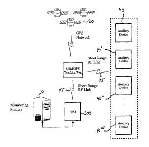
[0018] Figure 1 shows a block diagram of a system in accordance with the
invention. The system includes a central monitoring system (CMS) 10, a
tracking tag 20
operable to communicate with a Global Positioning Satellite (GPS) network 30
and one
or more auxiliary devices 40. The strap or tag may incorporate tamper
detection using
a variety of well-know technologies. The tag 20 can be attached to an object
or
individual using a strap or other suitable means of connection. For example,
the tag
can be attached to a package that is being transported from one location to
another. In
the alternative, the tag can be attached to in individual under "house arrest"
that being
-5-
CA 02662023 2009-02-26
WO 2008/027985 PCT/US2007/077142
monitored for compliance. Numerous other scenarios can be envisioned without
departing from the scope of the invention.
[00191 The tag 20 communicates with the GPS network 30 and a Home
Monitoring Unit (HMU) 300 to respectively obtain geographic location
information and to
exchange data with the CMS 10. The CMS monitors the location of the tag (as
well as
the object or individual to which the tag is attached) and compares the
monitored
location to a database of acceptable and unacceptable location and time
parameters.
The tag generally transmits position data updates, via the HMU, to the CMS and
also
receives downloads and updates from the CMS via the HMU.
[0020] In order to track one or more individuals or objects, each of which
having
an individual set of allowed geographic and temporal restrictions, the CMS 10
maintains
a database 15 of individuals or objects and corresponding restrictions. In one
embodiment, the tag 20 generally incorporates a microcontroller, flash memory,
an RF
transceiver, a GPS receiver, tamper detection, and a rechargeable battery into
a single
unit as discussed in more detail below. While the foregoing description
focuses
primarily on tracking of individuals, it is understood that the invention is
equally
applicable to the tracking of objects as well.
[0021] In system applications where the location of a plurality of individuals
are
being monitored and tracked, each such individual is provided with a tracking
tag. To
lengthen battery life and reduce data accumulation, each of the tags
preferably reports
into the CMS 10 on an intermittent or periodic basis. The reporting basis can
be on a
predetermined schedule and/or can be based upon detection of a violation or
other
reportable condition detected by the tag itself. Information reporting by the
various tags
is recorded and analyzed at the CMS to determine if individual violations have
occurred.
The CMS can then take an appropriate action to notify, respond to and/or
correct the
noted violation.
[00221 The system can also include one or more auxiliary device 40. The
auxiliary device 40 works in conjunction with the tag 20 which will
intermittently or
periodically request the presence of an auxiliary device 40 by sending out a
RF
transmission ("ping") and waiting for a reply from any auxiliary device in
range via the
short range radio (or RF) link 45. The typical range in an exemplary system is
CA 02662023 2009-02-26
WO 2008/027985 PCT/US2007/077142
approximately 100 meters in open area. The auxiliary device includes: power
supply
circuitry (e.g., for AC or DC power), battery charging circuitry, a battery
backup for
remote operations, a RF transceiver, a microcontroller and various alarm
features to
detect and report movement, power loss and light ingress as discussed in more
detail
below. Each auxiliary device can be identified by a unique serial number which
is
transmitted in its response to a ping from tag 20. The auxiliary device serial
number
can also be transmitted in a last reported alarm status response. The
auxiliary device
40 can store any alarms in non volatile memory to ensure that in the event of
loss of
power data is retained. The auxiliary device can also retain the status of any
alarms
until it is able to reply to a valid request from tag 20.
I - Tracking Tag
[00231 Figure 2 is a block diagram of a tag 20 in accordance with the
invention.
The tag 20 has a microcontroller 102, associated flash memory 104 and a GPS
receiver
106 which provides up GPS position information to the microcontroller 102.
Active tags
can include a cellular modem with an associated SIM card provided for data
communication between the tag 20 and the CMS 10. However, Figure 1 shows a
"passive" tag 20 that communicates through a short range RF link 45 and HMU
300 in
order to communicate with the CMS 10. This configuration is particularly
useful in
house arrest or work release scenarios. The tag 20 also communicates with one
or
more GPS satellites in the GPS network 30. The tag 20 also includes an RF
transceiver
150 for communication between the tag and the auxiliary device 40 via the RF
link 45.
This RF link creates an electronic tether between the tag and the auxiliary
device.
Suitable short range wireless integrated circuits and networking firmware for
use in
accordance with the invention are available from a variety of sources
including Micrel
Inc., of San Jose, CA (www.micrel.com). In the embodiment discussed below, the
tag
communicates with the monitoring station via the RF link and a cellular modem
is not
used. As noted above, a tag that communicates with the CMS via an RF link
(without
the benefit of a cellular modem) is referred to herein as a "passive" tag.
Communication
via the RF link 45 is discussed in more detail in the following section.
-7-
CA 02662023 2009-02-26
WO 2008/027985 PCT/US2007/077142
[0024] The tag can obtain position data through the GPS network 30. The CMS
can also determine the location of the tag based on the known position of an
auxiliary
device or HMU. The tag also includes a battery 112 to power the
microcontroller 102,
the GPS receiver 106 and the other components within the tag 20. The battery
112
resides within the unit in a sealed compartment and is not removed for
recharging so as
to avoid potential leaks which could result from removal and replacement of
the battery.
Because the unit must be worn by an individual at all times, the tag will be
subjected to
water in such environments as showering. The battery 112 is recharged while it
remains within the tag 20 by means of charger 113.
[0025] The tag may also include a tamper detection mechanism 114 to avoid
unauthorized removal or opening of the tag. The specific tamper detection
mechanism
can be implemented in a variety of ways including: i) signal continuity
detection, ii)
electrical, optical or electromagnet switches or detectors that detect
unauthorized
opening of the tag and/or iii) electrical, thermal proximity devices which
monitor the
proximity of the tag to the individual or object. Accelerometer 115 is also
provided and
can be used to monitor acceleration of the tag 20. The microcontroller 102 can
be
programmed to generate an alarm based on acceleration beyond a threshold or
the like.
[0026] The microcontroller 102 controls the operation of the tag 20. Regular
polls
of the GPS receiver 106 and RF transceiver 150 are carried out to monitor for
incoming
command messages and to monitoring the location of the tag. The parameters of
the
monitoring to be performed are programmed into the microcontroller 102 to
respond to
variations in the location of the tag and to respond to commands received from
the CMS
through the HMU 300.
[0027] The flash memory 104 holds the programmed code for the operation of
the tag 20. The code is downloaded to the unit utilizing a serial link and can
be modified
and/or downloaded through the HMU 300. In the alternative, the code can be
downloaded via programming port 124.
[0028] Communication between the tag 20 and the CMS 10 is carried out via the
HMU 300. The tag can also be polled by the CMS to download the position of the
tag
as measured by the GPS system and/or to download other operating parameters
such
as violation history, position history and/or battery status.
-8-
CA 02662023 2009-02-26
WO 2008/027985 PCT/US2007/077142
[0029] The microcontroller 102 is programmed to monitor for alarm conditions,
such as violations of restrictions by the tag wearer. In the event that an
alarm condition
occurs, for example low battery voltage, a tamper detection by the tamper
prevention
unit 114 or a violation of the geographic limitations set for the wearer of
the tag, the
microcontroller communicates an alarm condition to the CMS 10. The
microcontroller
can run continuously or can be programmed to cycle the entire tag through an
intermittent power pattern, such as a sleep mode, to conserve battery power.
[0030] The microcontroller code also includes the ability to be manually
placed
into a sleep mode wherein the unit is not powered down but only inactive, upon
receipt
of an appropriate command from the CMS 10. Powering down of the tag 20 can be
used to prolong the life of the battery 112. By allowing a power down to be
controlled by
the CMS, the tag can be powered down without the knowledge of the offender.
Because
the individual does not know when the unit is inactive, the individual cannot
take
advantage of inactivity to commit an offense without detection. The unit can
reactivate
after a set period of time, after being connected to a recharger or after
receipt of a
command to reactivate.
[0031] The GPS module is used with an appropriate antenna 116, such as a
patch antenna mounted internal to the tag case. The GPS module can also
include a
battery backup 130 to minimize the drain on the main battery 112. The GPS
module
when activated will obtain the current position of the tag. If no fix is
obtained, the tag will
report that no fix was obtained. To minimize the power consumption and
therefore
maximize the battery charge life, the GPS receiver is used in the push to fix
mode. The
receiver is normally asleep and, only when requested, wakes to obtain the
current
position of the tag.
[0032] The tag 20 can include an audible alarm such as a buzzer 118, a tactile
alarm such as a vibrator 120 to provide an indication to the wearer that a
condition
requiring attention has been detected. The tag can also include a panic button
122 to
allow the wearer to alert the CMS 10 that a situation requiring attention
exists. This
button can be particularly useful when the tag is used by an individual being
monitored
because of the individuals potential need for assistance. Other visual alerts
such as
-9-
CA 02662023 2009-02-26
WO 2008/027985 PCT/US2007/077142
Tricolor LED 126 (e.g., for system status and the like) and Tamper LED 128 can
be
provided.
11 - Auxiliary device
[0033] Figure 3 shows a block diagram of an auxiliary device 40 in accordance
with the invention. A "passive" auxiliary device 40 has a microcontroller 202
with
associated internal memory and an RF transceiver 250 for communication between
the
tag 20 and the auxiliary device 40 via the RF link 45. It is understood that
the
microcontroller 202 can utilize internal memory, external memory or both. The
auxiliary
device also includes a battery 212 to power the microcontroller 202, RF
transceiver 250
and the other components within the auxiliary device. The battery 212 is
recharged by
means of charger 213. The programming code for microcontroller 202 can be
downloaded via typical techniques. For example, the programming for
microcontroller
202 can be burned into the appropriate memory device prior to or during
assembly. In
the alternative, programming code can be downloaded via optional programming
port
224.
.[0034] The auxiliary device can optionally include a tamper detection
mechanism
214 to avoid unauthorized removal or opening of the auxiliary device. An
accelerometer
215 can optionally be provided and can be used to monitor movement of the
auxiliary
device. The microcontroller 202 can be programmed to generate an alarm based
on
acceleration beyond a threshold or the like. The auxiliary device 40 may also
include an
audible alarm such as a buzzer 218 to provide an indication that a condition
requiring
attention has been detected. The auxiliary device is preferable constructed
with a small
housing (e.g., 120mm * 80mm * 55mm ) and can be attached to AC power via a
suitable
cable or adapter (e.g., 12V adapter). The auxiliary device can be designed to
be hard
mounted via screws or other suitable fasteners. In the alternative the
auxiliary device
can be temporarily placed in a location or even worn or carried by an
individual (e.g.,
operating via battery power). For example, the auxiliary device can be
integrated into or
attached to an article of clothing such as shoes, socks, pants, shirts, or
jackets. In the
alternative, the auxiliary device can be integrated into or attached to a
backpack, purse,
wallet or other convenient portable accessory.
- io -
CA 02662023 2009-02-26
WO 2008/027985 PCT/US2007/077142
[0035] In operation, the tag 20 will periodically poll (e.g., ping) for the
presence of
an auxiliary device 40 via the RF link 45. If an auxiliary device is detected
(i.e., the
auxiliary device responds to the ping) and communications can be established
with the
auxiliary device, the operational parameters of the tag and/or the system can
be altered.
The auxiliary device 40 will typically reply to a tag 20 with some or all of
the following
information: auxiliary device ID, tag ID, Status of the tag (tamper, low
battery and
charging), status of the auxiliary device (tamper, motion or power). This
information is
then transmitted to the CMS 10 via the HMU. It understood that a variety of
communications protocols are suitable for use in accordance with the
invention. It is
also understood that in some embodiments, communications between the tag and
the
auxiliary device can be initiated by the auxiliary device.
[0036] Several modes of operation are discussed in detail below. In each of
these examples, the tag 20 relays messages though an auxiliary device or HMU
to the
CMS via a short range RF link. This configuration is advantageous in that the
tag and
the auxiliary device do not require a cellular modem to communicate to the
CMS. This
results in considerable cost savings and minimizes power utilization. It is
understood
that the auxiliary device may optionally include other communication and
processing
capabilities so that it can function as an HMU. In this case the auxiliary
device is
considered "active" and includes optional communications capabilities or
communications hardware 252 can include one or more of the following: a modem,
cellular modem, network connection, wireless communications device or the like
to
facilitate communication with the CMS.
III - Inclusion Zone Operation (GPS Power Down)
[0037] In this mode of operation, the location of the auxiliary device 40 or
HMU
300 is fixed and is known to the CMS 10 (e.g., the location of the auxiliary
device is
stored in the CMS database 15). The system is operable to establish an
inclusion zone
defined by the range of the auxiliary device. In this mode, so long as the tag
20 is in
communication with the auxiliary device or HMU, the CMS knows the location of
the tag
20. Operation in this mode proceeds as follows: the tag 20 detects an
auxiliary device
or HMU (i.e., the auxiliary device or HMU responds to a ping). The tag
establishes
- 11 -
CA 02662023 2009-02-26
WO 2008/027985 PCT/US2007/077142
communications with the auxiliary device or HMU, and reports some or all of
the
following information t6 the CMS 10: location information, auxiliary device
ID, tag ID,
Status of the tag (tamper, low battery and charging), status of the auxiliary
device
(tamper, motion or power). The auxiliary device can also be configured to
recognize
one or more auxiliary device groups (e.g., 40, 40', 40", 40"') and then alter
its operating
mode subject to a receipt from the auxiliary device that it has no alarms
pending.
[0038] As an additional precaution, software in the tag 20 or the CMS may
require a valid GPS fix before entering a low power mode. The tag 20 will
contact the
CMS 10 to confirm it is going to sleep (i.e., GPS receiver 106 can be powered
down in
order to save battery power). In cases where the tag is unable to contact the
CMS, the
tag can maintain list of approved auxiliary devices and the tag can make the
determination on whether or not to enter a reduced power state. This list of
approved
auxiliary devices can be updated by the CMS as needed. This mode is
particularly
advantageous in locations where GPS reception is impaired.
[0039] In some cases, the individual to which the tag is attached may be
permitted to travel outside the range of the HMU or an auxiliary device (e.g.,
to travel to
work or another acceptable location). If the tag 20 cannot calculate its
position via GPS,
contact the CMS 10 or if the tag receives an alarm status from the auxiliary
device 40, it
will remain in normal operating mode and will continue to log its status. The
logged
information can then be transmitted to the CMS once communication is
established
between the tag and the HMU or auxiliary device. It is understood that the
location of
the auxiliary device 40 can be fixed after the auxiliary device is powered up
in a given
location. Upon the initial communication between the tag and the CMS, the
system can
enter the location of the auxiliary device 40 into the database 15 before
allowing the tag
to enter a low power mode.
[0040] During low power mode, the tag 20 will continue to check for tampers on
both itself and the auxiliary device 40. Also during low power mode, the tag
20 can
increase its ping rate to the auxiliary device 40 to ensure it remains in
range. The ping
rate can be set to a random period between two time ranges to minimize
contention with
other RF devices. The tag 20 can receive a response from any member of its
associated auxiliary device group and will remain asleep. During this mode,
the tag 20
-12-
CA 02662023 2009-02-26
WO 2008/027985 PCT/US2007/077142
can also be configured to wake up at pre-set intervals to refresh its GPS
position and
therefore update its empheris and almanac from any GPS satellites in view.
This
ensures that when the tag 20 finally leaves range of an auxiliary device 40,
it is able to
quickly obtain a GPS position. The tag 20 can also be configured to contact
the CMS
at this point and report its status without the need to obtain a new GPS
position
before going back to low power mode.
[0041] Upon an alarm condition (e.g., power loss, movement or tamper, lack of
valid pings ...) the tag 20 will wake up and resume normal mode. The tag 20
will
immediately contact the CMS 10 and report its status.
IV - HMU Range Expansion
[0042] One or more auxiliary devices can also be used to extend the range of a
Home Monitoring Unit (HMU) when used in a traditional "house arrest"
situation. This is
shown graphically in Figure 4. In general, the HMU 300 communicates with the
CMS
10 via long range communication link 302 (typically a land line telephone link
to the
PSTN). It is understood that communications link 302 can utilize a modem,
cellular
modem, a network connection, wireless communications device or other hardware
that
can facilitate long range communications. In this scenario, the HMU is also
provided
with an RF receiver that is operable to monitor the RF link (or electronic
tether)
established between a tag 20 and an auxiliary device 40. Each auxiliary device
40 can
be positioned such that it can receive information from a tag 20 via the RF
link 45. The
auxiliary device 40 is also positioned in range of the HMU. This allows the
HMU
receiver to receive the reply message (from the auxiliary device to the tag)
even when
the tag is out of range. Receipt of the reply from the auxiliary device in
effect allows the
HMU to determine that the tag is within an acceptable range. The auxiliary
device will
only be treated as a valid source if it is previously assigned to the HMU and
is not in a
current alarm status.
V - RF Network Contention - RF Frequency Allocation
[0043] In the scenarios discussed above, the RF link 45 is utilized for
communication between various devices. In certain scenarios, several devices
may be
-13-
CA 02662023 2009-02-26
WO 2008/027985 PCT/US2007/077142
utilized in relatively close proximity. These devices may ultimately be in
contention for
use of the RF link, That is two or more devices may try to communicate via the
RF link
simultaneously. Accordingly, the RF link can be implemented to eliminate or
reduce
contention issues. For example, the RF link can be implemented with a
plurality of
frequencies that are allocated to various devices. In another example, the RF
link can
be implemented with a time slot allocation for each device. Such time slots
can be
assigned on a fixed or dynamic basis.
[0044] In the example shown in Table 1 below, the RF link 45 is implemented
with four frequencies.
Frequency No. Associated Device Description
1 HMU Dynamic Time Slot
Allocation
2 Auxiliary Device Frequency Allocation
3 Auxiliary Device Frequency Allocation
4 Auxiliary Device Frequency Allocation
[0045] In this example, frequency number 1 is utilized for communication
between a tag and an HMU. The frequency band is divided into a plurality of
time slots,
each of which can be assigned to a specific tag. Time slot allocation can be
performed
on a fixed or dynamic basis. In the case of fixed time slot allocation, the
given time slot
can be directly programmed into the specific tag as well as the associated HMU
prior to
any communication taking place. In the case of dynamic time slot allocation,
the tag
and HMU can conduct initial communications (e.g., utilizing a pre-selected
time slot)
before a specific time slot is assigned to a specific tag.
[0046] In this example, frequencies 2-4 are generally utilized by a tag to
communicate with an auxiliary device. In normal operation tag will
intermittently or
periodically request the presence of an auxiliary device by sending out a RF
transmission ("ping") and waiting for a reply from any auxiliary device in
range via the
RF link. Each ping can be transmitted on a different frequency (2-4) until
- 14 -
CA 02662023 2009-02-26
WO 2008/027985 PCT/US2007/077142
communication between the tag and the auxiliary device is established.
Specific
frequency can be selected on specific pattern or random frequency assignment.
Vl - Wireless Link - Range Adjustment
[0047] In certain scenarios, it may be desirable to adjust the range of the
wireless
(RF) link 45. For example, the default communication range between a tag 20
and an
auxiliary device 40 or HMU 300, 300' may extend into unintended areas such as
adjoining property. Accordingly, the receiver in the auxiliary device 40 or
HMU 300,
300' may include the capability to provide Received Signal Strength Indication
measurements (RSSI).
[0048] It is generally understood that RSSI measurements denote the received
radio signal strength. These measurements can be utilized in connection with a
variety
of system functions. For example, RSSI can be used internally in a wireless
networking
card to determine when the amount of radio energy in the channel is below a
certain
threshold at which point the network card is clear to send (CTS). RSSI can be
measured in the IF stage before the IF amplifier. In zero-IF systems, it can
be done in
the baseband signal chain, before the baseband amplifier. RSSI measurements
can be
output as a DC analog level. However, it is beneficial to sample RSSI
measurements
with an internal A/ D converter so that resulting numeric codes available
directly to the
internal processor 202 (Figure 3). In the example below, typical RSSI
measurements
range from about 250 (noise level) to about 650 maximum.
[0049] In the context herein, RSSI is utilized to determine the relative
proximity or
range of the tag 20 to an auxiliary device 40 or HMU 300, 300'. This can be
accomplished by selecting a pre determined RSSI value to set the acceptable
range of
the RF link 45 (i.e., the RSSI must remain above the pre-determined RSSI level
to be
considered within range). In the alternative, a calibration routine can be
utilized. For
example, the tag can be placed into a range calibration mode in which it pings
every few
seconds . The tag can then be moved throughout the desired location during
which the
auxiliary device 40 or HMU 300, 300' records the lowest RSSI measurement. Once
the
tag has been moved throughout the entire location at issue, the calibration
process is
complete and the lowest RSSI measured from the calibration process is used to
set the
-15-
CA 02662023 2012-05-23
range of the RF fink 45. The system can optionally include an acceptable
offset range
for the RSSI measurement (e.g., user selectable) to account for environmental
conditions. In this example, a typical default level for the offset range is
50. It is
understood that a variety of antenna types (e.g., omnidirectional, directional
...) having
various characteristics (gain, impedance, directionality, radiation efficiency
and the like)
can be utilized in combination with the RSSI based range adjustment discussed
above
to provide optimal coverage in a given scenario.
X - Suggested Uses of Each mode
[0050] 1) Inclusion Zone Operation (GPS Power Down)
[0051] To confirm the known location of an individual to the vicinity of an
auxiliary device or auxiliary device when GPS is unavailable i.e. at home or
in a
establishment i.e., hostel.
[0052] To extend the operational life of the tag battery by allowing the tag
to use the auxiliary device in a known location.
[0053] 2) HMU Range Expansion
[0054] To allow the auxiliary device to be positioned in such a way that
with the operation of the HMU, a property can be effectively covered with the
placement
of auxiliary device to extend the HMU range.
[0055] The auxiliary device can be used in a number of modes depending
on parameter settings on the tag and if a Home Monitoring unit (HMU is
present).
-16-