Note: Descriptions are shown in the official language in which they were submitted.
CA 02667079 2010-11-22
PARTICLE-MATRIX COMPOSITE DRILL BITS WITH HARDFACING
AND METHODS OF MANUFACTURING AND REPAIRING SUCH
DRILL BITS USING HARDFACING MATERIALS
10
TECHNICAL FIELD
The invention generally relates to particle-matrix composite drill bits and
other
tools that may be used in drilling subterranean formations, and to abrasive,
wear-resistant
hardfacing materials that may be used on surfaces of such particle-matrix
composite drill
bits and tools. The invention also relates to methods for applying abrasive,
wear-resistant
hardfacing to surfaces of particle-matrix composite drill bits and tools.
BACKGROUND
A conventional fixed-cutter, or "drag," rotary drill bit for drilling
subterranean
formations includes a bit body having a face region thereon carrying cutting
elements for
cutting into an earth formation. The bit body may be secured to a hardened
steel shank
having a threaded pin connection, such as an API threaded pin, for attaching
the drill bit to
a drill string that includes tubular pipe segments coupled end-to-end between
the drill bit
and other drilling equipment. Equipment such as a rotary table or top drive
may be used
for rotating the tubular pipe and drill bit. Alternatively, the shank may be
coupled to the
drive shaft of a down hole motor to rotate the drill bit independently of, or
in conjunction
with, a rotary table or top drive.
Typically, the bit body of a drill bit is formed from steel or a combination
of a
steel blank embedded in a particle-matrix composite material that includes
hard particulate
material, such as tungsten carbide, infiltrated with a molten binder material
such as a
I
CA 02667079 2010-11-22
copper alloy. The hardened steel shank generally is secured to the bit body
after the bit
body has been formed. Structural features may be provided at selected
locations on and in
the bit body to facilitate the drilling process. Such structural features may
include, for
example, radially and longitudinally extending blades, cutting element
pockets, ridges,
lands, nozzle ports, and drilling fluid courses and passages. The cutting
elements
generally are secured to cutting element pockets that are machined into blades
located on
the face region of the bit body, e.g., the leading edges of the radially and
longitudinally
extending blades. These structural features, such as the cutting element
pockets, may also
be formed by a mold used to form the bit body when the molten binder material
is
infiltrated into the hard particulate material. Advantageously, a particle-
matrix composite
material provides a bit body of higher strength and toughness compared to
steel material,
but still requires complex and labor-intensive processes for fabrication, as
described in
United States Patent Application Publication No. 2007/0102199. Therefore, it
would be
desirable to provide a method of manufacturing suitable for producing a bit
body that
includes a particle-matrix composite material that does not require
infiltration of hard
particulate material with a molten binder material.
Generally, the cutting elements of a conventional fixed-cutter rotary drill
bit each
include a cutting surface comprising a hard, superabrasive material, such as
mutually
bound particles of polycrystalline diamond. Such "polycrystalline diamond
compact"
(PDC) cutters have been employed on fixed-cutter rotary drill bits in the oil
and gas well
drilling industries for several decades.
FIG. I illustrates a conventional fixed-cutter rotary drill bit 10 generally
according
to the description above. The rotary drill bit 10 includes a bit body 12 that
is coupled to a
steel shank 14. A bore (not shown) is formed longitudinally through a portion
of the drill
bit 10 for communicating drilling fluid to a face 20 of the drill bit 10 via
nozzles 19 during
drilling operations. Cutting elements 22 (typically polycrystalline diamond
compact
(PDC) cutting elements) generally are bonded to the face 20 of the bit body 12
by methods
such as brazing, adhesive bonding, or mechanical affixation.
A drill bit 10 may be used numerous times to perform successive drilling
operations during which the surfaces of the bit body 12 and cutting elements
22 may be
subjected to extreme forces and stresses as the cutting elements 22 of the
drill bit 10 shear
away the underlying earth formation. These extreme forces and stresses cause
the cutting
elements 22 and the surfaces of the bit body 12 to wear. Eventually, the
surfaces of the bit
2
CA 02667079 2009-03-19
WO 2008/042329 PCT/US2007/021071
body 12 may wear to an extent at which the drill bit 10 is no longer suitable
for use.
Therefore, there is a need in the art for enhancing the wear-resistance of the
surfaces of the
bit body 12. Also, the cutting elements 22 may wear to an extent at which they
are no
longer suitable for use.
FIG. 2 is an enlarged view of a PDC cutting element 22 like those shown in
FIG. 1
secured to the bit body 12. Typically, the cutting elements 22 are fabricated
separately
from the bit body 12 and secured within pockets 21 formed in the outer, or
exterior,
surface of the bit body 12 with a bonding material 24 such as an adhesive or,
more
typically, a braze alloy as previously discussed herein. Furthermore, if the
cutting element
22 is a PDC cutter, the cutting element 22 may include a polycrystalline
diamond compact
table 28 secured to a cutting element body or substrate 23, which may be
unitary or
comprise two components bonded together.
Conventional bonding material 24 is much less resistant to wear than are other
portions and surfaces of the drill bit 10 and of cutting elements 22. During
use, small
vugs, voids and other defects may be formed in exposed surfaces of the bonding
material
24 due to wear. Solids-laden drilling fluids and formation debris generated
during the
drilling process may further erode, abrade and enlarge the small vugs and
voids in the
bonding material 24. The entire cutting element 22 may separate from the drill
bit body
12 during a drilling operation if enough bonding material 24 is removed. Loss
of a cutting
element 22 during a drilling operation can lead to rapid wear of other cutting
elements and
catastrophic failure of the entire drill bit 10. Therefore, there is also a
need in the art for an
effective method for enhancing the wear-resistance of the bonding material to
help prevent
the loss of cutting elements during drilling operations.
Ideally, the materials of a rotary drill bit must be extremely hard to
withstand
abrasion and erosion attendant to drilling earth formations without excessive
wear. Due to
the extreme forces and stresses to which drill bits are subjected during
drilling operations,
the materials of an ideal drill bit must simultaneously exhibit high fracture
toughness. In
practicality, however, materials that exhibit extremely high hardness tend to
be relatively
brittle and do not exhibit high fracture toughness, while materials exhibiting
high fracture
toughness tend to be relatively soft and do not exhibit high hardness. As a
result, a
compromise must be made between hardness and fracture toughness when selecting
materials for use in drill bits.
3
CA 02667079 2009-03-19
WO 2008/042329 PCT/US2007/021071
In an effort to simultaneously improve both the hardness and fracture
toughness of
rotary drill bits, composite materials have been applied to the surfaces of
drill bits that are
subjected to extreme wear. These composite or hard particle materials are
often referred
to as "hardfacing" materials and typically include at least one phase that
exhibits relatively
high hardness and another phase that exhibits relatively high fracture
toughness.
FIG. 3 is a representation of a photomicrograph of a polished and etched
surface of
a conventional hardfacing material applied upon the particulate-matrix
composite
material, as mentioned above, of a bit body. The hardfacing material includes
tungsten
carbide particles 40 substantially randomly dispersed throughout an iron-based
matrix of
matrix material 46. The tungsten carbide particles 40 exhibit relatively high
hardness,
while the matrix material 46 exhibits relatively high fracture toughness.
Tungsten carbide particles 40 used in hardfacing materials may comprise one or
more of cast tungsten carbide particles, sintered tungsten carbide particles,
and
macrocrystalline tungsten carbide particles. The tungsten carbide system
includes two
stoichiometric compounds, WC and W2C, with a continuous range of mixtures
therebetween. Cast tungsten carbide particles generally include a eutectic
mixture of the
WC and W2C compounds. Sintered tungsten carbide particles include relatively
smaller
particles of WC bonded together by a matrix material. Cobalt and cobalt alloys
are often
used as matrix materials in sintered tungsten carbide particles. Sintered
tungsten carbide
particles can be formed by mixing together a first powder that includes the
relatively
smaller tungsten carbide particles and a second powder that includes cobalt
particles. The
powder mixture is formed in a "green" state. The green powder mixture then is
sintered at
a temperature near the melting temperature of the cobalt particles to form a
matrix of
cobalt material surrounding the tungsten carbide particles to form particles
of sintered
tungsten carbide. Finally, macrocrystalline tungsten carbide particles
generally consist of
single crystals of WC.
Various techniques known in the art may be used to apply a hardfacing material
such as that represented in FIG. 3 to a surface of a drill bit. A welding rod
may be
configured as a hollow, cylindrical tube formed from the matrix material of
the hardfacing
material that is filled with tungsten carbide particles. At least one end of
the hollow,
cylindrical tube may be sealed. The sealed end of the tube then may be melted
or welded
onto the desired surface on the drill bit. As the tube melts, the tungsten
carbide particles
within the hollow, cylindrical tube mix with and are suspended in the molten
matrix
4
CA 02667079 2009-03-19
WO 2008/042329 PCT/US2007/021071
material as it is deposited onto the drill bit. An alternative technique
involves forming a
cast rod of the hardfacing material and using either an arc or a torch to
apply or weld
hardfacing material disposed at an end of the rod to the desired surface on
the drill bit.
One method of applying the hardfacing material by torch is to use what is
known as oxy
fuel gas welding. Oxy fuel gas welding is a group of welding processes which
produces
coalescence by heating materials with an oxy fuel gas flame or flames with or
without the
application of pressure to apply the hardfacing material. One so called oxy
fuel gas
welding is known as oxygen-acetylene welding (OAW) which is acceptable for
applying a
hardfacing material to a surface of a drill bit.
Arc welding techniques also may be used to apply a hardfacing material to a
surface of a drill bit. For example, a plasma transferred arc may be
established between
an electrode and a region on a surface of a drill bit on which it is desired
to apply a
hardfacing material. A powder mixture including both particles of tungsten
carbide and
particles of matrix material then may be directed through or proximate the
plasma-transferred arc onto the region of the surface of the drill bit. The
heat generated by
the arc melts at least the particles of matrix material to form a weld pool on
the surface of
the drill bit, which subsequently solidifies to form the hardfacing material
layer on the
surface of the drill bit.
When a hardfacing material is applied to a surface of a drill bit, relatively
high
temperatures are used to melt at least the matrix material. At these
relatively high
temperatures, dissolution may occur between the tungsten carbide particles and
the matrix
material. In other words, after applying the hardfacing material, at least
some atoms
originally contained in a tungsten carbide particle (tungsten and carbon, for
example) may
be found in the matrix material surrounding the tungsten carbide particle. In
addition, at
least some atoms originally contained in the matrix material (iron, for
example) may be
found in the tungsten carbide particles. FIG. 4 is an enlarged view of a
tungsten carbide
particle 40 shown in FIG. 3. At least some atoms originally contained in the
tungsten
carbide particle 40 (tungsten and carbon, for example) may be found in a
region 47 of the
matrix material 46 immediately surrounding the tungsten carbide particle 40.
The region
47 roughly includes the region of the matrix material 46 enclosed within the
phantom line
48. In addition, at least some atoms originally contained in the matrix
material 46 (iron,
for example) may be found in a peripheral or outer region 41 of the tungsten
carbide
5
CA 02667079 2010-11-22
particle 40. The outer region 41 roughly includes the region of the tungsten
carbide
particle 40 outside the phantom line 42.
Dissolution between the tungsten carbide particle 40 and the matrix material
46
may embrittle the matrix material 46 in the region 47 surrounding the tungsten
carbide
particle 40 and reduce the hardness of the tungsten carbide particle 40 in the
outer region
41 thereof, reducing the overall effectiveness of the hardfacing material.
Dissolution is a
process of dissolving a solid, such as the tungsten carbide particle 40, into
a liquid, such as
the matrix material 46, particularly when at elevated temperatures and when
the matrix
material 46 is in its liquid phase which transforms the material composition
of the matrix
material. In one aspect, dissolution is the process where a solid substance
enters
(generally at elevated temperatures) a molten matrix material which changes
the
composition of the matrix material. Dissolution occurs more rapidly as the
temperature of
the matrix material 46 approaches the melting temperature of tungsten carbide
particle 40.
For example, an iron-based matrix material will have greater dissolution of
the tungsten
carbide particles 40 than a nickel-based matrix material will, because of the
higher
temperatures required in order to bring the iron-based matrix material into a
molten state
during application. Therefore, there is a need in the art for abrasive, wear-
resistant
hardfacing materials that include a matrix material that allows for
dissolution between
tungsten carbide particles and the matrix material to be minimized. There is
also a need in
the art for methods of applying such abrasive wear-resistant hardfacing
materials to
surfaces of particle-matrix composite drill bits, and for drill bits and
drilling tools that
include such particle-matrix composite materials.
DISCLOSURE OF THE INVENTION
A rotary drill bit is provided that provides a particle-matrix composite
material
devoid of a molten binder or infiltrant material as is conventionally employed
in so-called
"matrix"-type drill bits. Such a drill bit may also be characterized as having
a "sintered"
particle-matrix composite structure. Further, the rotary drill bit includes an
abrasive,
wear-resistant material, which may be characterized as a "hardfacing"
material, for
enhancing the wear-resistance of surfaces of the drill bit.
6
CA 02667079 2010-11-22
Accordingly, in embodiments of the invention there is provided a rotary drill
bit
for drilling at least one subterranean formation, the rotary drill bit
comprising:
a bit body at least substantially comprised of a pressed and sintered particle-
matrix
composite material and having an exposed exterior surface, the pressed and
sintered
particle-matrix composite material comprising a plurality of hard particles
randomly
dispersed throughout a matrix material, the hard particles selected from the
group
consisting of diamond, boron carbide, boron nitride, aluminum nitride, and
carbides or
borides of the group consisting of W, Ti, Mo, Nb, V, Hf, Zr, and Cr, the
matrix material
selected from the group consisting of cobalt-based alloys, iron-based alloys,
nickel-based
alloys, cobalt- and nickel-based alloys, iron- and nickel-based alloys, iron-
and
cobalt-based alloys, and titanium-based alloys; and
an abrasive wear-resistant material disposed in at least one recess extending
into
the bit body from the exposed exterior surface of the bit body, an exposed
surface of the
abrasive wear-resistant material being at least substantially level with the
exposed exterior
surface of the bit body adjacent the abrasive wear-resistant material taken in
a direction
generally perpendicular to the exposed exterior surface of the bit body
adjacent the
abrasive wear-resistant material, wherein the abrasive wear-resistant material
disposed in
at least one recess extending into the bit body comprises the following
materials in
pre-application ratios:
another matrix material, the another matrix material comprising between
about 20% and about 50% by weight of the abrasive wear-resistant material, the
another
matrix material comprising at least 75% nickel by weight, the another matrix
material
having a melting point of less than about 1100 C;
a plurality of -10 ASTM mesh sintered tungsten carbide pellets
substantially randomly dispersed throughout the another matrix material, the
plurality of
sintered tungsten carbide pellets comprising between about 30% and about 55%
by weight
of the abrasive wear-resistant material, each sintered tungsten carbide pellet
comprising a
plurality of tungsten carbide particles bonded together with a binder alloy,
the binder alloy
having a melting point greater than about 1200 C; and
a plurality of -18 ASTM mesh cast tungsten carbide granules substantially
randomly dispersed throughout the another matrix material, the plurality of
cast tungsten
carbide granules comprising less than about 35% by weight of the abrasive wear-
resistant
material.
6a
CA 02667079 2010-11-22
In other embodiments of the invention there is provided a method for applying
an
abrasive wear-resistant material to a surface of a drill bit, the method
comprising:
providing a drill bit body substantially comprised of a pressed and sintered
particle-matrix composite material, the bit body having an exposed exterior
surface and at
least one recess extending into the bit body from the exposed exterior surface
of the bit
body, the pressed and sintered particle-matrix composite material comprising a
plurality of
hard particles randomly dispersed throughout a matrix material, the hard
particles selected
from the group consisting of diamond, boron carbide, boron nitride, aluminum
nitride, and
carbides or borides of the group consisting of W, Ti, Mo, Nb, V, Hf, Zr, and
Cr, the matrix
material selected from the group consisting of cobalt-based alloys, iron-based
alloys,
nickel-based alloys, cobalt-and nickel-based alloys, iron- and nickel-based
alloys, iron-
and cobalt-based alloys, and titanium-based alloys;
mixing a plurality of -10 ASTM mesh sintered tungsten carbide pellets and a
plurality of -18 ASTM mesh cast tungsten carbide granules in another matrix
material to
provide a pre-application abrasive wear-resistant material, the another matrix
material
comprising at least 75% nickel by weight, the another matrix material having a
melting
point of less than about 1455 C, each sintered tungsten carbide pellet
comprising a
plurality of tungsten carbide particles bonded together with a binder alloy,
the binder alloy
having a melting point greater than about 1200 C, the another matrix material
comprising
between about 20% and about 60% by weight of the pre-application abrasive
wear-resistant material, the plurality of sintered tungsten carbide pellets
comprising
between about 30% and about 55% by weight of the pre-application abrasive
wear-resistant material, the plurality of cast tungsten carbide granules
comprising less than
about 35% by weight of the pre-application abrasive wear-resistant material;
heating the another matrix material, comprising heating at least a portion of
the
pre-application abrasive wear-resistant material to a temperature above the
melting point
of the another matrix material;
applying the molten another matrix material, at least some of the sintered
tungsten
carbide pellets, and at least some of the cast tungsten carbide granules into
the at least one
recess extending into the bit body;
solidifying the another molten matrix material to form the abrasive wear-
resistant
material in the at least one recess; and
6b
CA 02667079 2010-11-22
causing a surface of the abrasive wear-resistant material to be substantially
level
with the exterior surface of the bit body adjacent the abrasive wear-resistant
material in a
direction taken generally perpendicular to the exterior surface of the bit
body adjacent the
abrasive wear-resistant material.
Other advantages, features and alternative aspects of the invention will
become
apparent when viewed in light of the detailed description of the various
embodiments of
the invention when taken in conjunction with the attached drawings and
appended claims.
BRIEF DESCRIPTION OF THE DRAWINGS
While the specification concludes with claims particularly pointing out and
distinctly claiming that which is regarded as the invention, the advantages of
this invention
may be more readily ascertained from the following description of the
invention when
read in conjunction with the accompanying drawings in which:
FIG. 1 is a perspective view of a convention rotary drill bit that includes
cutting
elements;
FIG. 2 is an enlarged view of a cutting element of the conventional drill bit
shown
in FIG. 1;
FIG. 3 is a representation of a photomicrograph of a conventional abrasive
wear-
resistant material that includes tungsten carbide particles substantially
randomly dispersed
throughout a matrix material;
FIG. 4 is an enlarged view of a conventional tungsten carbide particle shown
in
FIG. 3;
FIG. 5 is a side view of a fixed0cutter rotary drill bit illustrating
generally
longitudinally extending recesses formed in a blade of the drill bit for
receiving abrasive
wear-resistant hardfacing material thereon;
FIG. 6 is a partial side view of one blade of the fixed-cutter rotary drill
bit shown
in FIG. 5 illustrating the various portions thereof,
FIG. 7A is a cross-sectional view of a blade of the fixed-cutter rotary drill
bit
illustrated in FIG. 5, taken generally perpendicular to the longitudinal axis
of the drill bit;
further illustrating the recesses formed in the blade for receiving abrasive
wear-resistant
hardfacing material therein;
FIG. 7B is a cross-sectional view of the blade of the fixed-cutter rotary
drill bit
illustrated in FIG. 5 similar to that shown in FIG. 7A, and further
illustrating abrasive
wear-resistant hardfacing material disposed in the recesses previously
provided in the
blade;
7
CA 02667079 2009-03-19
WO 2008/042329 PCT/US2007/021071
FIG. 8 is a side view of another fixed-cutter rotary drill bit, similar to
that shown
in FIG. 5, illustrating generally circumferentially extending recesses formed
in a blade of
the drill bit for receiving abrasive wear-resistant hardfacing material
therein;
FIG. 9 is a side view of yet another fixed-cutter rotary drill bit, similar to
those
shown in FIGS. 5 and 8, illustrating both generally longitudinally extending
recesses and
generally circumferentially extending recesses formed in a blade of the drill
bit for
receiving abrasive wear-resistant hardfacing material therein;
FIG. 10 is a cross-sectional view, similar to those shown in FIGS. 7A and 7B,
illustrating recesses formed generally around a periphery of a wear-resistant
insert
provided in a formation-engaging surface of a blade of a rotary drill bit for
receiving
abrasive wear-resistant hardfacing material therein;
FIG. 11 is a perspective view of a cutting element secured to a blade of a
rotary
drill bit, and illustrating recesses formed generally around a periphery of
the cutting
element for receiving abrasive wear-resistant hardfacing material therein;
FIG. 12 is a cross-sectional view of a portion of the cutting element and
blade
shown in FIG. 11, taken generally perpendicular to the longitudinal axis of
the cutting
element, further illustrating the recesses formed generally around the
periphery of the
cutting element;
FIG. 13 is another cross-sectional view of a portion of the cutting element
and
blade shown in FIG. 11, taken generally parallel to the longitudinal axis of
the cutting
element, further illustrating the recesses formed generally around the
periphery of the
cutting element;
FIG. 14 is a perspective view of the cutting element and blade shown in FIG.
11,
further illustrating abrasive wear-resistant hardfacing material disposed in
the recesses
provided around the periphery of the cutting element;
FIG. 15 is a cross-sectional view of the cutting element and blade like that
shown
in FIG. 12, further illustrating the abrasive wear-resistant hardfacing
material provided in
the recesses around the periphery of the cutting element;
FIG. 16 is a cross-sectional view of the cutting element and blade like that
shown
in FIG. 13, further illustrating the abrasive wear-resistant hardfacing
material provided in
the recesses formed around the periphery of the cutting element;
FIG. 17 is a perspective view of a cutting element and blade like that shown
in
FIG. 11 and further embodies teachings of the invention;
8
CA 02667079 2009-03-19
WO 2008/042329 PCT/US2007/021071
FIG. 18 is a lateral cross-sectional view of the cutting element shown in FIG.
17
taken along section line 18-18 therein;
FIG. 19 is a longitudinal cross-sectional view of the cutting element shown in
FIG. 17 taken along section line 19-19 therein;
FIG. 20 is an end view of yet another fixed-cutter rotary drill bit
illustrating
generally recesses formed in nose and cone regions of blades of the drill bit
for receiving
abrasive wear-resistant hardfacing material therein;
FIG. 21 is a representation of a photomicrograph of an abrasive wear-resistant
material that embodies teachings of the invention and that includes tungsten
carbide
particles substantially randomly dispersed throughout a matrix;
FIG. 22 is an enlarged view of a tungsten carbide particle shown in FIG. 21;
FIGS. 23A-23B are photomicrographs of an abrasive wear-resistant hardfacing
material that embodies teachings of the invention and that includes tungsten
carbide
particles substantially randomly dispersed throughout a matrix; and
FIGS. 24A-24E illustrate a method of forming the bit body having a
particle-matrix composite material therein, similar to the rotary drill bit
shown in FIG. 20.
MODE(S) FOR CARRYING OUT THE INVENTION
The illustrations presented herein are, in some instances, not actual views of
any
particular drill bit, cutting element, hardfacing material or other feature of
a drill bit, but
are merely idealized representations which are employed to describe the
present invention.
Additionally, like elements and features among the various drawing figures are
identified
for convenience with the same or similar reference numerals.
Embodiments of the invention may be used to enhance the wear resistance of
rotary drill bits, particularly rotary drill bits having a particle-matrix
composite material
composition with an abrasive wear-resistant hardfacing material applied to
surface
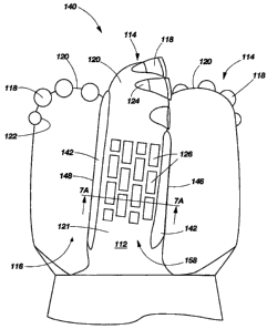
portions thereof. A rotary drill bit 140 in accordance with an embodiment of
the invention
is shown in FIG. 5. The drill bit 140 includes a bit body 112 that has
generally radially
projecting and longitudinally extending wings or blades 114, which are
separated by junk
slots 116. As shown in FIG. 6, each of the blades 114 may include a cone
region 150, a
nose region 152, a flank region 154, a shoulder region 156, and a gage region
158 (the
flank region 154 and the shoulder region 156 may be collectively referred to
in the art as
either the "flank" or the "shoulder" of the blade). In some embodiments, the
blades 114
may not include a cone region 150. Each of these regions includes an outermost
surface
9
CA 02667079 2009-03-19
WO 2008/042329 PCT/US2007/021071
that is configured to engage the subterranean formation surrounding a well
bore hole
during drilling. The cone region 150, nose region 152 and flank region 154 are
configured
and positioned to engage the formation surfaces at the bottom of the well bore
hole and to
support the majority of the so-called "weight-on-bit" (WOB) applied through
the drill
string. These regions carry a majority of the cutting elements 118 attached
within
pockets 122 upon faces 120 of the blades 114 for cutting or scraping away the
underlying
formation at the bottom of the well bore. The shoulder region 156 is and
configured and
positioned to bridge the transition between the bottom of the well bore hole
and the wall
thereof and the gage region 158 is configured and positioned to engage the
formation
surfaces on the lateral sides of the well bore hole.
As the formation-engaging surfaces of the various regions of the blades 114
slide
and scrape against the formation during application of WOB and rotation to
drill a
formation, the material of the blades 114 at the formation-engaging surfaces
thereof has a
tendency to wear away. This wearing away of the material of the blades 114 at
the
formation-engaging surfaces may lead to loss of cutting elements and/or bit
instability
(e.g., bit whirl), which may further lead to catastrophic failure of the drill
bit 140.
In an effort to reduce the wearing away of the material of the blades 114 at
the
formation-engaging surfaces, various wear-resistant structures and materials
have been
placed on and/or in these surfaces of the blades 114. For example, inserts
such as bricks,
studs, and wear knots formed from an abrasive wear-resistant material, such
as, for
example, tungsten carbide, have been inset in formation-engaging surfaces of
blades 114.
As shown in FIG. 5, a plurality of wear-resistant inserts 126 (each of which
may
comprise, for example, a tungsten carbide brick) may be inset within the blade
114 at the
formation-engaging surface 121 of the blade 114 in the gage region 158
thereof. In
additional embodiments, the blades 114 may include wear-resistant structures
on or in
formation-engaging surfaces of other regions of the blades 114, including the
cone region
150, nose region 152, flank region 154, and shoulder region 156 as described
with respect
to FIG. 6. For example, abrasive wear-resistant inserts may be provided on' or
in the
formation-engaging surfaces of the cone region 150 and/or nose region 152 of
the
blades 114 rotationally behind one or more cutting elements 118.
Abrasive wear-resistant hardfacing material (i.e., hardfacing material) also
may be
applied at selected locations on the formation-engaging surfaces of the blades
114. For
example, a torch for applying an oxygen-acetylene weld (OAW) or an arc welder,
for
CA 02667079 2009-03-19
WO 2008/042329 PCT/US2007/021071
example, may be used to at least partially melt the wear-resistant hardfacing
material to
facilitate application of the wear-resistant hardfacing material to the
surfaces of the
blades 114. Application of the wear-resistant hardfacing material, i.e.,
hardfacing
material, to the bit body 112 is described below.
With continued reference to FIG. 5, recesses 142 for receiving abrasive
wear-resistant hardfacing material therein may be formed in the blades 114. By
way of
example and not limitation, the recesses 142 may extend generally
longitudinally along
the blades 114, as shown in FIG. 5. A longitudinally extending recess 142 may
be formed
or otherwise provided along the edge defined by the intersection between the
formation-engaging surface 121 and the rotationally leading surface 146 of the
blades 114.
In addition, a longitudinally extending recess 142 may be formed or otherwise
provided
along the edge defined by the intersection between the formation-engaging
surface 121
and the rotationally trailing surface 148 of the blades 114. One or more of
the recesses
142 may extend along the blade 114 adjacent one or more wear-resistant inserts
126.
FIG. 7A is a cross-sectional view of a blade 114 shown in FIG. 5 taken along
section line 7A-7A shown therein. As shown in FIG. 7A, the recesses 142 may
have a
generally semicircular cross-sectional shape. The invention is not so limited,
however,
and in additional embodiments, the recesses 142 may have a cross-sectional
shape that is
generally triangular, generally rectangular (e.g., square), or any other
shape.
The manner in which the recesses 142 are formed or otherwise provided in the
blades 114 may depend on the material from which the blades 114 have been
formed. For
example, if the blades 114 comprise cemented carbide or other particle-matrix
composite
material, as described below, the recesses 142 may be formed in the blades 114
using, for
example, a conventional milling machine or other conventional machining tool
(including
hand-held machining tools). Optionally, the recesses 142 may be provided in
the blades
114 during formation of the blades 114. The invention is not limited by the
manner in
which the recesses 142 are formed in the blades 114 of the bit body 112 of the
drill bit
140, however, and any method that can be used to form the recesses 142 in a
particular
drill bit 140 may be used to provide drill bits that embody teachings of the
invention.
As shown in FIG. 7B, abrasive wear-resistant hardfacing material 160 may be
provided in the recesses 142. In some embodiments, the exposed exterior
surfaces of the
abrasive wear-resistant hardfacing material 160 provided in the recesses 142
may be
substantially coextensive with the adjacent exposed exterior surface of the
blade 114. In
11
CA 02667079 2009-03-19
WO 2008/042329 PCT/US2007/021071
other words, the abrasive wear-resistant hardfacing material 160 may not
project
significantly from the surface of the blades 114. In this configuration, the
topography of
the exterior surface of the blades 114 after filling the recesses 142 with the
abrasive
wear-resistant hardfacing material 160 may be substantially similar to the
topography of
the exterior surface of the blades 114 prior to forming the recesses 142.
Stated yet another
way, the exposed surfaces of the abrasive wear-resistant hardfacing material
160 may be
substantially level, or flush, with the surface of the blade 114 adjacent the
wear-resistant
hardfacing material 160 in a direction generally perpendicular to the region
of the blade
114 adjacent the wear-resistant hardfacing material 160. By substantially
maintaining the
original topography of the exterior surfaces of the blades 114, the forces
applied to the
exterior surfaces of the blades 114 may be more evenly distributed across the
blades 114
in a manner intended by the bit designer. In contrast, when abrasive wear-
resistant
hardfacing material 160 projects from the exterior surfaces of the blades 114,
as the
formation engages these projections of abrasive wear-resistant hardfacing
material 160,
increased localized stresses may develop within the blades 114 in the areas
proximate the
projections of abrasive wear-resistant hardfacing material 160. The magnitude
of these
increased localized stresses may be generally proportional to the distance by
which the
projections extend from the surface of the blades 114 in the direction towards
the
formation being drilled. Therefore, by configuring the exposed exterior
surfaces of the
abrasive wear-resistant hardfacing material 160 to substantially match the
exposed
exterior surfaces of the blades 114 removed when forming the recesses 142,
these
increased localized stresses may be reduced or eliminated, which may lead to
decreased
wear and increased service life of the drill bit 140.
It is recognized in other embodiments of the invention, hardfacing material
may
optionally be applied directly to the face 120 of the bit body 112 without
creating recesses
142 while still enhancing the wear-resistance of the surfaces of the bit body.
FIG. 8 illustrates another rotary drill bit 170 according to an embodiment of
the
invention. The drill bit 170 is generally similar to the drill bit 140
previously described
with reference to FIG. 5, and includes a plurality of blades 114 separated by
junk
slots 116. A plurality of wear-resistant inserts 126 are inset within the
formation-engaging
surface 121 of each blade 114 in the gage region 158 of the bit body 112. The
drill bit 170
further includes a plurality of recesses 172 formed adjacent the region of
each blade 114
comprising the plurality of wear-resistant inserts 126. The recesses 172 may
be generally
12
CA 02667079 2009-03-19
WO 2008/042329 PCT/US2007/021071
similar to the recesses 142 previously described herein in relation to FIGS.
5, 6, 7A, and
7B. The recesses 172 within the face 120 of the bit, however, extend generally
circumferentially around the drill bit 170 in a direction generally parallel
to the direction
of rotation of the drill bit 170 during drilling.
FIG. 9 illustrates yet another drill bit 180 that embodies teachings of the
invention.
The fixed-cutter rotary drill bit 180 is generally similar to the drill bit
140 and the drill bit
170, and includes a plurality of blades 114, junk slots 116, and wear-
resistant inserts 126
inset within the formation-engaging surface 121 of each blade 114 in the gage
region 158
thereof. The drill bit 180, however, includes both generally longitudinally
extending
recesses 142 like those of the drill bit 140 and generally circumferentially
extending
recesses 172 like those of the drill bit 170. In this configuration, each
plurality of
wear-resistant inserts 126 may be substantially peripherally surrounded by
recesses 142,
172 that are filled with abrasive wear-resistant hardfacing material 160 (FIG.
7B)
generally up to the exposed exterior surface of the blades 114. By
substantially
surrounding the periphery of each region of the blade 114 comprising a
plurality of
wear-resistant inserts 126, wearing away of the material of the blade 114
adjacent the
plurality of wear-resistant inserts 126 may be reduced or eliminated, which
may prevent
loss of one or more of the wear-resistant inserts 126 during drilling.
In the embodiment shown in FIG. 9, the regions of the blades 114 comprising a
plurality of wear-resistant inserts 126 are substantially peripherally
surrounded by recesses
142, 172 that may be filled with abrasive wear-resistant hardfacing material
160 (FIG.
7B). In additional embodiments, one or more wear-resistant inserts of a drill
bit may be
individually substantially peripherally surrounded by recesses filled with
abrasive
wear-resistant hardfacing material.
FIG. 10 is a cross-sectional view of a blade 114 of another drill bit that
embodies
teachings of the invention. The cross-sectional view is similar to the cross-
sectional views
shown in FIGS. 7A-7B. The blade 114 shown in FIG. 10, however, includes a
wear-resistant insert 126 that is individually substantially peripherally
surrounded by
recesses 182 that are filled with abrasive wear-resistant hardfacing material
160. The
recesses 182 may be substantially similar to the previously described recesses
142, 172
(FIGS. 5, 8 and 9) and may be filled with abrasive wear-resistant hardfacing
material 160.
In this configuration, the exposed exterior surfaces of the insert 126,
abrasive
wear-resistant hardfacing material 160, and regions of the blade 114 adjacent
the abrasive
13
CA 02667079 2009-03-19
WO 2008/042329 PCT/US2007/021071
wear-resistant hardfacing material 160 may be generally coextensive and planar
to reduce
or eliminate localized stress concentration caused by any abrasive wear-
resistant
hardfacing material 160 projecting from the blade 114 generally towards a
formation
being drilled.
In additional embodiments, recesses may be provided around cutting elements.
FIG. 11 is a perspective view of one cutting element 118 secured within a
pocket 122 on a
blade 114 of a drill bit similar to each of the previously described drill
bits. As shown in
each of FIGS. 11-13, recesses 190 may be formed in the blade 114 that
substantially
peripherally surround the cutting element 118. As shown in FIGS. 12-13, the
recesses 190
may have a cross-sectional shape that is generally triangular, although, in
additional
embodiments, the recesses 190 may have any other shape. The cutting element
118 may
be secured within the pocket 122 using a bonding material 124 such as, for
example, an
adhesive or brazing alloy may be provided at the interface and used to secure
and attach
the cutting element 118 to the blade 114.
FIGS. 14-16 are substantially similar to FIGS. 11-13, respectively, but
further
illustrate abrasive wear-resistant hardfacing material 160 disposed within the
recesses 190
provided around the cutting element 118. The exposed exterior surfaces of the
abrasive
wear-resistant hardfacing material 160 and the regions of the blade 114
adjacent the
abrasive wear-resistant hardfacing material 160 may be generally coextensive.
Furthermore, abrasive wear-resistant hardfacing material 160 may be configured
so as not
to extend beyond the adjacent surfaces of the blade 114 to reduce or eliminate
localized
stress concentration caused by any abrasive wear-resistant hardfacing material
160
projecting from the blade 114 generally towards a formation being drilled.
Additionally, in this configuration, the abrasive wear-resistant hardfacing
material 160 may cover and protect at least a portion of the bonding material
124 used to
secure the cutting element 118 within the pocket 122, which may protect the
bonding
material 124 from wear during drilling. By protecting the bonding material 124
from
wear during drilling, the abrasive wear-resistant hardfacing material 160 may
help to
prevent separation of the cutting element 118 from the blade 114, damage to
the bit body,
and catastrophic failure of the drill bit.
FIGS. 17-19 are substantially similar to FIGS. 11-13, respectively, but
further
illustrate abrasive wear-resistant hardfacing material 160 disposed upon the
bonding
material 124 securing the cutting element 118 to the rotary drill bit 140. The
rotary drill
14
CA 02667079 2009-03-19
WO 2008/042329 PCT/US2007/021071
bit 140 is structurally similar to the rotary drill bit 10 shown in FIG. 1,
and includes a
plurality of cutting elements 118 positioned and secured within pockets
provided on the
outer surface of a bit body 112. As illustrated in FIG. 17, each cutting
element 118 may
be secured to the bit body 112 of the drill bit 140 along an interface
therebetween. A
bonding material 124 such as, for example, an adhesive or brazing alloy may be
provided
at the interface and used to secure and attach each cutting element 118 to the
bit body 112.
The bonding material 124 may be less resistant to wear than the materials of
the bit body
112 and the cutting elements 118. Each cutting element 118 may include a
polycrystalline
diamond compact table 128 attached and secured to a cutting element body or
substrate
123 along an interface.
The rotary drill bit 140 further includes an abrasive wear-resistant material
160
disposed on a surface of the drill bit 140. Moreover, regions of the abrasive
wear-resistant
material 160 may be configured to protect exposed surfaces of the bonding
material 124.
FIG. 18 is a lateral cross sectional view of the cutting element 118 shown in
FIG. 17 taken along section line 18-18 therein. As illustrated in FIG. 18,
continuous
portions of the abrasive wear-resistant material 160 may be bonded both to a
region of the
outer surface of the bit body 112 and a lateral surface of the cutting element
118 and each
continuous portion may extend over at least a portion of the interface between
the bit body
112 and the lateral sides of the cutting element 118.
FIG. 19 is a longitudinal cross sectional view of the cutting element 118
shown in
FIG. 17 taken along section line 19-19 therein. As illustrated in FIG. 19,
another
continuous portion of the abrasive wear-resistant material 160 may be bonded
both to a
region of the outer surface of the bit body 112 and a lateral surface of the
cutting element
118 and may extend over at least a portion of the interface between the bit
body 112 and
the longitudinal end surface of the cutting element 118 opposite the a
polycrystalline
diamond compact table 128. Yet another continuous portion of the abrasive wear-
resistant
material 160 may be bonded both to a region of the outer surface of the bit
body 112 and a
portion of the exposed surface of the polycrystalline diamond compact table
128. The
continuous portion of the abrasive wear-resistant material 160 may extend over
at least a
portion of the interface between the bit body 112 and the face of the
polycrystalline
diamond compact table 128.
In this configuration, the continuous portions of the abrasive wear-resistant
material 160 may cover and protect at least a portion of the bonding material
124 disposed
CA 02667079 2009-03-19
WO 2008/042329 PCT/US2007/021071
between the cutting element 118 and the bit body 112 from wear during drilling
operations. By protecting the bonding material 124 from wear during drilling
operations,
the abrasive wear-resistant material 160 helps to prevent separation of the
cutting element
118 from the bit body 112 during drilling operations, damage to the bit body
112, and
catastrophic failure of the rotary drill bit 140.
The continuous portions of the abrasive wear-resistant material 160 that cover
and
protect exposed surfaces of the bonding material 124 may be configured as a
bead or
beads of abrasive wear-resistant material 160 provided along and over the
edges of the
interfacing surfaces of the bit body 112 and the cutting element 118. The
abrasive
wear-resistant material 160 provides an effective method for enhancing the
wear-resistance of the bonding material 124 to help prevent the loss of
cutting
elements 118 during drilling operations
FIG. 20 is an end view of yet another rotary drill bit 200. As shown in FIG.
20, in
some embodiments of the invention, recesses 202 may be provided between
cutting
elements 118. For example, the recesses 202 may extend generally
circumferentially
about a longitudinal axis of the bit (not shown) between cutting elements 118
positioned
in the cone region 150 (FIG. 6) and/or the nose region 152 (FIG. 6).
Furthermore, as
shown in FIG. 20, in some embodiments of the invention, recesses 204 may be
provided
rotationally behind cutting elements 118. For example, the recesses 204 may
extend
generally longitudinally along a blade 114 rotationally behind one or more
cutting
elements 118 positioned in the cone region 150 (FIG. 6) and/or the nose region
152 (FIG.
6). In additional embodiments, the recesses 204 may not be elongated and may
have a
generally circular or a generally rectangular shape. Such recesses 204 may be
positioned
directly rotationally behind one or more cutting elements 118, or rotationally
behind
adjacent cutting elements 118, but at a radial position (measured from the
longitudinal
axis of the drill bit 200) between the adjacent cutting elements 118. The
abrasive
wear-resistant material may be applied in the recesses 202, 204 or may be
applied upon
other surfaces of the rotary drill bit in order to help reduce wear.
The abrasive wear-resistant hardfacing materials described herein may
comprise,
for example, a ceramic-metal composite material (i.e., a "cermet" material)
comprising a
plurality of hard ceramic phase regions or particles dispersed throughout a
metal matrix
material. The hard ceramic phase regions or particles may comprise carbides,
nitrides,
oxides, and borides (including boron carbide (B4C)). More specifically, the
hard ceramic
16
CA 02667079 2009-03-19
WO 2008/042329 PCT/US2007/021071
phase regions or particles may comprise carbides and borides made from
elements such as
W, Ti, Mo, Nb, V, Hf, Ta, Cr, Zr, Al, and Si. By way of example and not
limitation,
materials that may be used to form hard ceramic phase regions or particles
include
tungsten carbide, titanium carbide (TiC), tantalum carbide (TaC), titanium
diboride
(TiB2), chromium carbides, titanium nitride (TiN), aluminium oxide (A1203),
aluminium
nitride (AIN), and silicon carbide (SiC). The metal matrix material of the
ceramic-metal
composite material may include, for example, cobalt-based, iron-based, nickel-
based,
iron- and nickel-based, cobalt- and nickel-based, iron- and cobalt-based,
aluminum-based,
copper-based, magnesium-based, and titanium-based alloys. The matrix material
may
also be selected from commercially pure elements such as cobalt, aluminum,
copper,
magnesium, titanium, iron, and nickel.
In embodiments of the invention, the abrasive wear-resistant hardfacing
materials
may be applied to a bit body or tool body and include materials as described
below. As
used herein, the term "bit" includes not only conventional drill bits, but
also core bits,
bicenter bits, eccentric bits and tools employed in drilling of a well bore.
FIG. 21 represents a polished and etched surface of an abrasive wear-resistant
material 54 according to an embodiment of the invention, particularly suitable
for
applying the material as a "hardfacing" upon a drill bit having a particle-
matrix composite
material. FIGS. 23A and 23B are actual photomicrographs of a polished and
etched
surface of an abrasive wear-resistant material according to embodiments of the
invention.
Referring to FIG. 21, the abrasive wear-resistant material 54 includes a
plurality of
sintered tungsten carbide pellets 56 and a plurality of cast tungsten carbide
granules 58
substantially randomly dispersed throughout a matrix material 60. Each
sintered tungsten
carbide pellet 56 may have a generally spherical pellet configuration. The
term "pellet" as
used herein means any particle having a generally spherical shape. Pellets are
not true
spheres, but lack the corners, sharp edges, and angular projections commonly
found in
crushed and other non spherical tungsten carbide particles. In some
embodiments of the
invention, the cast tungsten carbide granules may be or include cast tungsten
carbide
pellets, as shown in FIG. 23B. In still other embodiments of the invention,
the cast
tungsten carbide granules may be or include crushed cast tungsten carbide or
crushed
sintered tungsten carbide, as shown in FIG. 23A.
Corners, sharp edges, and angular projections may produce residual stresses,
which may cause tungsten carbide material in the regions of the particles
proximate the
17
CA 02667079 2009-03-19
WO 2008/042329 PCT/US2007/021071
residual stresses to melt at lower temperatures during application of the
abrasive
wear-resistant material 54 to a surface of a drill bit. Melting or partial
melting of the
tungsten carbide material during application may facilitate dissolution
between the
tungsten carbide particles and the surrounding matrix material. As previously
discussed
herein, dissolution between the matrix material 60 and the sintered tungsten
carbide pellets
56 and cast tungsten carbide granules 58 may embrittle the matrix material 60
in regions
surrounding the tungsten carbide pellets 56, and cast tungsten carbide
granules 58 and
may reduce the toughness of the hardfacing material, particularly when the
matrix
material 60 is iron based. Such dissolution may degrade the overall physical
properties of
the abrasive wear-resistant material 54. The use of sintered tungsten carbide
pellets 56
(and, optionally, cast tungsten carbide pellets 58) instead of conventional
tungsten carbide
particles that include corners, sharp edges, and angular projections may
reduce such
dissolution, preserving the physical properties of the matrix material 60 and
the sintered
tungsten carbide, pellets 56 (and, optionally, the cast tungsten carbide
pellets 58) during
application of the abrasive wear-resistant material 54 to the surfaces of
drill bits and other
tools.
The matrix material 60 may comprise between about 20% and about 50% by
weight of the abrasive wear-resistant material 54. More particularly, the
matrix material
60 may comprise between about 35% and about 45% by weight of the abrasive
wear-resistant material 54. The plurality of sintered tungsten carbide pellets
56 may
comprise between about 30% and about 55% by weight of the abrasive wear-
resistant
material 54. Furthermore, the plurality of cast tungsten carbide granules 58
may comprise
less than about 35% by weight of the abrasive wear-resistant material 54. More
particularly, the plurality of cast tungsten carbide granules 58 may comprise
between
about 10% and about 35% by weight of the abrasive wear-resistant material 54.
For
example, the matrix material 60 may be about 40% by weight of the abrasive
wear-resistant material 54, the plurality of sintered tungsten carbide pellets
56 may be
about 48% by weight of the abrasive wear-resistant material 54, and the
plurality of cast
tungsten carbide granules 58 may be about 12% by weight of the abrasive wear-
resistant
material 54.
The sintered tungsten carbide pellets 56 may be larger in size than the cast
tungsten carbide granules 58. Furthermore, the number of cast tungsten carbide
granules
58 per unit volume of the abrasive wear-resistant material 54 may be higher
than the
18
CA 02667079 2009-03-19
WO 2008/042329 PCT/US2007/021071
number of sintered tungsten carbide pellets 56 per unit volume of the abrasive
wear-resistant material 54.
The sintered tungsten carbide pellets 56 may include -10 ASTM (American
Society for Testing and Materials) mesh pellets. As used herein, the phrase "-
10 ASTM
mesh pellets" means pellets that are capable of passing through an ASTM No. 10
U.S.A.
standard testing sieve. Such sintered tungsten carbide pellets may have an
average
diameter of less than about 1680 microns. The average diameter of the sintered
tungsten
carbide pellets 56 may be between about 0.8 times and about 20 times greater
than the
average diameter of the cast tungsten carbide granules 58. The cast tungsten
carbide
granules 58 may include -16 ASTM mesh granules. As used herein, the phrase "-
16
ASTM mesh granules" means granules that are capable of passing through an ASTM
No.
16 U.S.A. standard testing sieve. More particularly, the cast tungsten carbide
granules 58
may include -100 ASTM mesh granules. As used herein, the phrase "-100 ASTM
mesh
granules" means granules that are capable of passing through an ASTM No. 100
U.S.A.
standard testing sieve. Such cast tungsten carbide granules 58 may have an
average
diameter of less than about 150 microns.
As an example, the sintered tungsten carbide pellets 56 may include -20/+30
ASTM mesh pellets, and the cast tungsten carbide granules 58 may include -
100/+270
ASTM mesh granules. As used herein, the phrase "-20/+30 ASTM mesh pellets"
means
pellets that are capable of passing through an ASTM No. 20 U.S.A. standard
testing sieve,
but incapable of passing through an ASTM No. 30 U.S.A. standard testing sieve.
Such
sintered tungsten carbide pellets 56 may have an average diameter of less than
about 840
microns and greater than about 590 microns. Furthermore, the phrase "-100/+270
ASTM
mesh granules," as used herein, means granules capable of passing through an
ASTM No.
100 U.S.A. standard testing sieve, but incapable of passing through an ASTM
No. 270
U.S.A. standard testing sieve. Such cast tungsten carbide granules 58 may have
an
average diameter in a range from approximately 50 microns to about 150
microns.
As another example, the plurality of sintered tungsten carbide pellets 56 may
include a plurality of -60/+80 ASTM mesh sintered tungsten carbide pellets and
a plurality
of -120/+270 ASTM mesh sintered tungsten carbide pellets. The plurality of -
60/+80
ASTM mesh sintered tungsten carbide pellets may comprise between about 30% and
about 40% by weight of the abrasive wear-resistant material 54, and the
plurality of
-120/+270 ASTM mesh sintered tungsten carbide pellets may comprise between
about
19
CA 02667079 2009-03-19
WO 2008/042329 PCT/US2007/021071
15% and about 25% by weight of the abrasive wear-resistant material 54. As
used herein,
the phrase "-120/+270 ASTM mesh pellets" means pellets capable of passing
through an
ASTM No. 120 U.S.A. standard testing sieve, but incapable of passing through
an ASTM
No. 270 U.S.A. standard testing sieve. Such sintered tungsten carbide pellets
56 may have
an average diameter in a range from approximately 50 microns to about 125
microns.
In one particular embodiment, set forth merely as an example, the abrasive
wear-resistant material 54 may include about 40% by weight matrix material 60,
about
48% by weight -20/+30 ASTM mesh sintered tungsten carbide pellets 56, and
about 12%
by weight -140/+325 ASTM mesh cast tungsten carbide granules 58. As used
herein, the
phrase "-20/+30 ASTM mesh pellets" means pellets that are capable of passing
through an
ASTM No. 20 U.S.A. standard testing sieve, but incapable of passing through an
ASTM
No. 30 U.S.A. standard testing sieve. Similarly, the phrase "-140/+325 ASTM
mesh
pellets" means pellets that are capable of passing through an ASTM No. 140
U.S.A.
standard testing sieve, but incapable of passing through an ASTM No. 325
U.S.A.
standard testing sieve. The matrix material 60 may include a nickel-based
alloy, which
may further include one or more additional elements, such as, for example,
chromium,
boron, and silicon. The matrix material 60 also may have a melting point of
less than
about 1100 C, and may exhibit a hardness of between about 87 on the Rockwell B
Scale
and about 60 on the Rockwell C Scale. Hardness values herein are represented
of actual
or converted hardness microhardness determinations. More particularly, the
matrix
material 60 may exhibit a hardness of between about <20 and about 55 on the
Rockwell C
Scale. For example, the matrix material 60 may exhibit a hardness of about 40
on the
Rockwell C Scale.
Cast granules and sintered pellets of carbides other than tungsten carbide
also may
be used to provide abrasive wear-resistant materials that embody teachings of
the
invention. Such other carbides include, but are not limited to, chromium
carbide,
molybdenum carbide, niobium carbide, tantalum carbide, titanium carbide, and
vanadium
carbide.
The matrix material 60 may comprise a metal alloy material having a melting
point that is less than about 1460 C. More particularly, the matrix material
60 may
comprise a metal alloy material having a melting point that is less than about
1100 C.
Furthermore, each sintered tungsten carbide pellet 56 of the plurality of
sintered tungsten
carbide pellets 56 may comprise a plurality of tungsten carbide particles
bonded together
CA 02667079 2009-03-19
WO 2008/042329 PCT/US2007/021071
with a binder alloy having a melting point that is greater than about 1200 C.
For example,
the binder alloy may comprise a cobalt-based metal alloy material or a nickel-
based alloy
material having a melting point that is lower than about 1200 C. In this
configuration, the
matrix material 60 may be substantially melted during application of the
abrasive
wear-resistant material 54 to a surface of a drilling tool such as a drill bit
without
substantially melting the cast tungsten carbide granules 58, or the binder
alloy or the
tungsten carbide particles of the sintered tungsten carbide pellets 56. This
enables the
abrasive wear-resistant material 54 to be applied to a surface of a drilling
tool at relatively
lower temperatures to minimize dissolution between the sintered tungsten
carbide
pellets 56 and the matrix material 60 and between the cast tungsten carbide
granules 58
and the matrix material 60.
As previously discussed herein, minimizing atomic diffusion between the matrix
material 60 and the sintered tungsten carbide pellets 56 and cast tungsten
carbide granules
58, helps to preserve the chemical composition and the physical properties of
the matrix
material 60, the sintered tungsten carbide pellets 56, and the cast tungsten
carbide granules
58 during application of the abrasive wear-resistant material 54 to the
surfaces of drill bits
and other tools.
The matrix material 60 also may include relatively small amounts of other
elements, such as carbon, chromium, silicon, boron, iron, silver, and nickel.
Furthermore,
the matrix material 60 also may include a flux material such as
silicomanganese, an
alloying element such as niobium, and a binder such as a polymer material.
FIG. 22 is an enlarged view of a sintered tungsten carbide pellet 56 shown in
FIG. 21. The hardness of the sintered tungsten carbide pellet 56 may be
substantially
consistent throughout the pellet. For example, the sintered tungsten carbide
pellet 56 may
include a peripheral or outer region 57 of the sintered tungsten carbide
pellet 56. The
outer region 57 may roughly include the region of the sintered tungsten
carbide pellet 56
outside the phantom line 64. The outer region 61 roughly includes the region
of the
matrix material 60 enclosed within the phantom line 66. The sintered tungsten
carbide
pellet 56 may exhibit a first average hardness in the central region of the
pellet enclosed
by the phantom line 64, and a second average hardness at locations within the
peripheral
region 57 of the pellet outside the phantom line 64. The second average
hardness of the
sintered tungsten carbide pellet 56 may be greater than about 99% of the first
average
hardness of the sintered tungsten carbide pellet 56. As an example, the first
average
21
CA 02667079 2009-03-19
WO 2008/042329 PCT/US2007/021071
hardness may be about 91 on the Rockwell A Scale, and the second average
hardness may
be about 90 on the Rockwell A Scale for a nickel base matrix material and may
be about
86 on the Rockwell A Scale for an iron-based matrix material. It is to be
recognized that
prior to applying the hardfacing material 56, the sintered tungsten carbide
pellets may
exhibit an overall hardness of about 85 on the Rockwell A Scale to about 92 on
the
Rockwell A Scale when containing between about 16% Co to about 4% Co,
respectively.
Also, the sintered tungsten carbide pellets may have an average hardness on
the range of
89-91 on the Rockwell A Scale when containing about 6% Co. Generally during
application of the hardfacing material, nickel-based matrix composites usually
allows the
sintered tungsten carbide pellets to substantially maintain their original
hardness.
Whereas, iron-based matrix composites may partially dissolve the sintered
tungsten
carbide pellets near their edges, which may lower the after application
hardness by several
Rockwell points below its pre-application hardness.
The sintered tungsten carbide pellets 56 may have relatively high fracture
toughness relative to the cast tungsten carbide granules 58, while the cast
tungsten carbide
granules 58 may have relatively high hardness relative to the sintered
tungsten carbide
pellets 56. By using matrix materials 60 as described herein, the fracture
toughness of the
sintered tungsten carbide pellets 56 and the hardness of the cast tungsten
carbide granules
58 may be preserved in the abrasive wear-resistant material 54 during
application of the
abrasive wear-resistant material 54 to a drill bit or other drilling tool,
providing an
abrasive wear-resistant material 54 that is improved relative to abrasive wear-
resistant
materials known in the art.
Abrasive wear-resistant materials according to embodiments of the invention,
such
as the abrasive wear-resistant material 54 illustrated in FIGS. 21-22, may be
applied to
selected areas on surfaces of rotary drill bits (such as the rotary drill bit
10 shown in FIG.
1), rolling cutter drill bits (commonly referred to as "roller cone" drill
bits), and other
drilling tools that are subjected to wear, such as ream while drilling tools
and expandable
reamer blades, all such apparatuses and others being encompassed, as
previously
indicated, within the term "drill bit."
Certain locations on a surface of a drill bit may require relatively higher
hardness,
while other locations on the surface of the drill bit may require relatively
higher fracture
toughness. The relative weight percentages of the matrix material 60, the
plurality of
sintered tungsten carbide pellets 56, and the plurality of cast tungsten
carbide granules 58
22
CA 02667079 2009-03-19
WO 2008/042329 PCT/US2007/021071
may be selectively varied to provide an abrasive wear-resistant material 54
that exhibits
physical properties tailored to a particular tool or to a particular area on a
surface of a tool.
For example, the surfaces of cutting teeth on a rolling-cutter-type drill bit
may be
subjected to relatively high impact forces in addition to frictional-type
abrasive or grinding
forces. Therefore, abrasive wear-resistant material 54 applied to the surfaces
of the
cutting teeth may include a higher weight percentage of sintered tungsten
carbide pellets
56 in order to increase the fracture toughness of the abrasive wear-resistant
material 54. In
contrast, gage surfaces of a drill bit may be subjected to relatively little
impact force but
relatively high frictional-type abrasive or grinding forces. Therefore,
abrasive
wear-resistant material 54 applied to the gage surfaces of a drill bit may
include a higher
weight percentage of cast tungsten carbide granules 58 in order to increase
the hardness of
the abrasive wear-resistant material 54.
In addition to being applied to selected areas on surfaces of drill bits and
drilling
tools that are subjected to wear, the abrasive wear-resistant materials
according to
embodiments of the invention may be used to protect structural features or
materials of
drill bits and drilling tools that are relatively more prone to wear,
including the examples
presented above.
The abrasive wear-resistant material 54 may be used to cover and protect
interfaces between any two structures or features of a drill bit or other
drilling tool. For
example, the interface between a bit body and a periphery of wear knots or any
type of
insert in the bit body may be covered and protected by abrasive wear-resistant
material 54.
In addition, the abrasive wear-resistant material 54 is not limited to use at
interfaces
between structures or features and may be used at any location on any surface
of a drill bit
or drilling tool that is subjected to wear.
Abrasive wear-resistant materials according to embodiments of the invention,
such
as the abrasive wear-resistant material 54, may be applied to the selected
surfaces of a drill
bit or drilling tool using variations of techniques known in the art. For
example, a
pre-application abrasive wear-resistant material according to embodiments of
the
invention may be provided in the form of a welding rod. The welding rod may
comprise a
solid, cast or extruded rod consisting of the abrasive wear-resistant material
54.
Alternatively, the welding rod may comprise a hollow cylindrical tube formed
from the
matrix material 60 and filled with a plurality of sintered tungsten carbide
pellets 56 and a
plurality of cast tungsten carbide granules 58. An OAW torch or any other type
of gas
23
CA 02667079 2009-03-19
WO 2008/042329 PCT/US2007/021071
fuel torch may be used to heat at least a portion of the welding rod to a
temperature above
the melting point of the matrix material 60. This may minimize the extent of
atomic
diffusion occurring between the matrix material 60 and the sintered tungsten
carbide
pellets 56 and cast tungsten carbide granules 58.
The rate of dissolution occurring between the matrix material 60 and the
sintered
tungsten carbide pellets 56 and cast tungsten carbide granules 58 is at least
partially a
function of the temperature at which dissolution, occurs. The extent of
dissolution,
therefore, is at least partially a function of both the temperature at which
dissolution
occurs and the time for which dissolution is allowed to occur. Therefore, the
extent of
dissolution occurring between the matrix material 60 and the sintered tungsten
carbide
pellets 56 and the cast tungsten carbide granules 58 may be controlled by
employing good
heat management control.
The OAW torch may be capable of heating materials to temperatures in excess of
1200 C. It may be beneficial to slightly melt the surface of a drill bit or
drilling tool to
which the abrasive wear-resistant material 54 is to be applied just prior to
applying the
abrasive wear-resistant material 54 to the surface. For example, the OAW torch
may be
brought in close proximity to a surface of a drill bit or drilling tool and
used to heat to the
surface to a sufficiently high temperature to slightly melt or "sweat" the
surface. The
welding rod comprising pre-application wear-resistant material 54 may then be
brought in
close proximity to the surface, and the distance between the torch and the
welding rod
may be adjusted to heat at least a portion of the welding rod to a temperature
above the
melting point of the matrix material 60 to melt the matrix material 60. The
molten matrix
material 60, at least some of the sintered tungsten carbide pellets 56, and at
least some of
the cast tungsten carbide granules 58 may be applied to the surface of a drill
bit, and the
molten matrix material 60 may be solidified by controlled cooling. The rate of
cooling
may be controlled to control the microstructure and physical properties of the
abrasive
wear-resistant material 54.
Alternatively, the abrasive wear-resistant material 54 may be applied to a
surface
of a drill bit or drilling tool using an arc welding technique, such as a
plasma-transferred
arc welding technique. For example, the matrix material 60 may be provided in
the form
of a powder (small particles of matrix material 60). A plurality of sintered
tungsten
carbide pellets 56 and a plurality of cast tungsten carbide granules 58 may be
mixed with
the powdered matrix material 60 to provide a pre-application wear-resistant
material in the
24
CA 02667079 2009-03-19
WO 2008/042329 PCT/US2007/021071
form of a powder mixture. A plasma-transferred arc welding machine then may be
used to
heat at least a portion of the pre-application wear-resistant material to a
temperature above
the melting point of the matrix material 60 and less than about 1200 C to melt
the matrix
material 60.
Other welding techniques, such as metal inert gas (MIG) arc welding
techniques,
tungsten inert gas (TIG) arc welding techniques, and flame spray welding
techniques are
known in the art and may be used to apply the abrasive wear-resistant material
54 to a
surface of a drill bit or drilling tool.
The abrasive wear-resistant material, i.e., hardfacing, is suitable for
application
upon a bit body made from particle-matrix composite material or so called
"cemented
carbide" material. The particle-matrix composite material for a bit body is
now presented
together with some terminology to facilitate a proper understanding of the
invention.
The term "green," as used herein, means unsintered.
The term "green bit body," as used herein, means an unsintered structure
comprising a plurality of discrete particles held together by a binder
material, the structure
having a size and shape allowing the formation of a bit body suitable for use
in an earth
boring drill bit from the structure by subsequent manufacturing processes
including, but
not limited to, machining and densification.
The term "brown," as used herein, means partially sintered.
The term "brown bit body," as used herein, means a partially sintered
structure
comprising a plurality of particles, at least some of which have partially
grown together to
provide at least partial bonding between adjacent particles, the structure
having a size and
shape allowing the formation of a bit body suitable for use in an earth boring
drill bit from
the structure by subsequent manufacturing processes including, but not limited
to,
machining and further densification. Brown bit bodies may be formed by, for
example,
partially sintering a green bit body.
The term "sintering," as used herein, means densification of a particulate
component involving removal of at least a portion of the pores between the
starting
particles (accompanied by shrinkage) combined with coalescence and bonding
between
adjacent particles.
As used herein, the term "[metal] -based alloy" (where [metal] is any metal)
means
commercially pure [metal] in addition to metal alloys wherein the weight
percentage of
CA 02667079 2009-03-19
WO 2008/042329 PCT/US2007/021071
[metal] in the alloy is greater than the weight percentage of any other
component of the
alloy.
As used herein, the term "material composition" means the chemical composition
and microstructure of a material. In other words, materials having the same
chemical
composition but a different microstructure are considered to have different
material
compositions.
As used herein, the term "tungsten carbide" means any material composition
that
contains chemical compounds of tungsten and carbon, such as, for example, WC,
W2C,
and combinations of WC and W2C. Tungsten carbide includes, for example, cast
tungsten carbide, sintered tungsten carbide, and macrocrystalline tungsten
carbide.
The rotary drill bit 140, as shown in FIG. 5, includes a bit body 112
substantially
formed from and composed of a particle-matrix composite material. The drill
bit 140 also
may include a shank (not shown) attached to the bit body 112. However, the bit
body 112
does not include a steel blank integrally formed therewith, as conventionally
required for
infiltrated particle-matrix materials as described above, for attaching the
bit body 112 to
the shank.
The particle-matrix composite material of the bit body 112 may include a
plurality
of hard particles randomly dispersed throughout a matrix material. The hard
particles may
comprise diamond or ceramic materials such as carbides, nitrides, oxides, and
borides
(including boron carbide (B4C)). More specifically, the hard particles may
comprise
carbides and borides made from elements such as W, Ti, Mo, Nb, V, Hf, Ta, Cr,
Zr, Al,
and Si. By way of example and not limitation, materials that may be used to
form hard
particles include tungsten carbide, titanium carbide (TiC), tantalum carbide
(TaC),
titanium diboride (TiB2), chromium carbides, titanium nitride (TiN), aluminium
oxide
(A1203), aluminium nitride (A1N), and silicon carbide (SiC). Furthermore,
combinations of
different hard particles may be used to tailor the physical properties and
characteristics of
the particle-matrix composite material. The hard particles may be formed using
techniques known to those of ordinary skill in the art. Most suitable
materials for hard
particles are commercially available and the formation of the remainder is
within the
ability of one of ordinary skill in the art.
The matrix material 60 of the particle-matrix composite material may include,
for
example, cobalt-based, iron-based, nickel-based, iron- and nickel-based,
cobalt- and
nickel-based, iron- and cobalt-based, aluminum-based, copper-based, magnesium-
based,
26
CA 02667079 2009-03-19
WO 2008/042329 PCT/US2007/021071
and titanium-based alloys. The matrix material may also be selected from
commercially
pure elements such as cobalt, aluminum, copper, magnesium, titanium, iron, and
nickel.
By way of example and not limitation, the matrix material may include carbon
steel, alloy
steel, stainless steel, tool steel, Hadfield manganese steel, nickel or cobalt
superalloy
material, and low thermal expansion iron- or nickel-based alloys such as INVAR
. As
used herein, the term "superalloy" refers to an iron-, nickel-, and cobalt-
based alloys
having at least 12% chromium by weight. Additional examples of alloys that may
be used
as matrix material include austenitic steels, nickel-based superalloys such as
INCONEL
625M or Rene 95, and INVAR -type alloys having a coefficient of thermal
expansion
that closely matches that of the hard particles used in the particular
particle-matrix
composite material. More closely matching the coefficient of thermal expansion
of matrix
material with that of the hard particles offers advantages such as reducing
problems
associated with residual stresses and thermal fatigue. Another example of a
suitable matrix
material is a Hadfield austenitic manganese steel (Fe with approximately 12%
Mn by
weight and 1.1 % C by weight).
In embodiments of the invention, the particle-matrix composite material may
include a plurality of -400 ASTM (American Society for Testing and Materials)
mesh
tungsten carbide particles. As used herein, the phrase "-400 ASTM mesh
particles" means
particles that pass through an ASTM No. 400 mesh screen as defined in ASTM
specification El 1 04 entitled Standard Specification for Wire Cloth and
Sieves for Testing
Purposes. Such tungsten carbide particles may have a diameter of less than
about 38
microns. A matrix material may include a metal alloy comprising about 50%
cobalt by
weight and about 50% nickel by weight. The tungsten carbide particles may
comprise
between about 60% and about 95% by weight of the particle-matrix composite
material,
and the matrix material may comprise between about 5% and about 40% by weight
of the
particle-matrix composite material. More particularly, the tungsten carbide
particles may
comprise between about 70% and about 80% by weight of the particle-matrix
composite
material, and the matrix material may comprise between about 20% and about 30%
by
weight of the particle-matrix composite material.
In another embodiment of the invention, the particle-matrix composite material
may include a plurality of -635 ASTM mesh tungsten carbide particles. As used
herein,
the phrase "-635 ASTM mesh particles" means particles that pass through an
ASTM No.
635 mesh screen as defined in ASTM specification El 1 04 entitled Standard
Specification
27
CA 02667079 2009-03-19
WO 2008/042329 PCT/US2007/021071
for Wire Cloth and Sieves for Testing Purposes. Such tungsten carbide
particles may have
a diameter of less than about 20 microns. A matrix material may include a
cobalt-based
metal alloy comprising substantially commercially pure cobalt. For example,
the matrix
material may include greater than about 98% cobalt by weight. The tungsten
carbide
particles may comprise between about 60% and about 95% by weight of the
particle-matrix composite material, and the matrix material may comprise
between about
5% and about 40% by weight of the particle-matrix composite material.
FIGS. 24A-24E illustrate a method of forming the bit body used in accordance
with embodiments of the invention set for above. The bit body, such as the bit
body 200
shown in FIG. 20, is substantially formed from and composed of a particle-
matrix
composite material. The method generally includes providing a powder mixture,
pressing
the powder mixture to form a green body, and at least partially sintering the
powder
mixture.
Referring to FIG. 24A, a powder mixture 78 may be pressed with substantially
isostatic pressure within a mold or container 80. The powder mixture 78 may
include a
plurality of the previously described hard particles and a plurality of
particles comprising a
matrix material, as also previously described herein. Optionally, the powder
mixture 78
may further include additives commonly used when pressing powder mixtures such
as, for
example, binders for providing lubrication during pressing and for providing
structural
strength to the pressed powder component, plasticizers for making the binder
more
pliable, and lubricants or compaction aids for reducing interparticle
friction.
The container 80 may include a fluid-tight deformable member 82. For example,
the fluid tight deformable member 82 may be a substantially cylindrical bag
comprising a
deformable polymer material. The container 80 may further include a sealing
plate 84,
which may be substantially rigid. The deformable member 82 may be formed from,
for
example, an elastomer such as rubber, neoprene, silicone, or polyurethane. The
deformable member 82 may be filled with the powder mixture 78 and vibrated to
provide
a uniform distribution of the powder mixture 78 within the deformable member
82. At
least one displacement or insert 86 may be provided within the deformable
member 82 for
defining features of the bit body, such as, for example, the longitudinal bore
15 (FIG. 6).
Alternatively, the insert 86 may not be used and the longitudinal bore 15 may
be formed
using a conventional machining process during subsequent processes. The
sealing plate
28
CA 02667079 2009-03-19
WO 2008/042329 PCT/US2007/021071
84 then may be attached or bonded to the deformable member 82 providing a
fluid-tight
seal therebetween.
The container 80 (with the powder mixture 78 and any desired inserts 86
contained therein) may be placed within a pressure chamber 90. A removable
cover 91
may be used to provide access to the interior of the pressure chamber 90. A
fluid (which
may be substantially incompressible) such as, for example, water, oil, or gas
(such as, for
example, air or nitrogen) is pumped into the pressure chamber 90 through an
opening 92
at high pressures using a pump (not shown). The high pressure of the fluid
causes the
walls of the deformable member 82 to deform. The fluid pressure may be
transmitted
substantially uniformly to the powder mixture 78. The pressure within the
pressure
chamber 90 during isostatic pressing may be greater than about 35 megapascals
(about
5,000 pounds per square inch). More particularly, the pressure within the
pressure
chamber 90 during isostatic pressing may be greater than about 138 megapascals
(about
20,000 pounds per square inch). In other methods, a vacuum may be provided
within the
container 80 and a pressure greater than about 0.1 megapascals (about 15
pounds per
square inch) may be applied to the exterior surfaces of the container 80 (by,
for example,
the atmosphere) to compact the powder mixture 78.. Isostatic pressing of the
powder
mixture 78 may form a green powder component or green bit body 94 shown in
FIG. 24B,
which can be removed from the pressure chamber 90 and container 80 after
pressing.
In another method of pressing the powder mixture 78 to form the green bit
body 94 shown in FIG. 24B, the powder mixture 78 may be pressed, such as with
a
uniaxial press, in a mold or die (not shown) using a mechanically or
hydraulically actuated
plunger by methods that are known to those of ordinary skill in the art of
powder
processing.
The green bit body 94 shown in FIG. 24B may include a plurality of particles
(hard particles and particles of matrix material) held together by a binder
material
provided in the powder mixture 78 (FIG. 24A), as previously described. Certain
structural
features may be machined in the green bit body 94 using conventional machining
techniques including, for example, turning techniques, milling techniques, and
drilling
techniques. Hand-held tools also may be used to manually form or shape
features in or on
the green bit body 94. By way of example and not limitation, blades 114, junk
slots 116
(FIG. 20), and surface 96 may be machined or otherwise formed in the green bit
body 94
to form a shaped green bit body 98 shown in FIG. 24C.
29
CA 02667079 2009-03-19
WO 2008/042329 PCT/US2007/021071
The shaped green bit body 98 shown in FIG. 24C may be at least partially
sintered
to provide a brown bit body 102 shown in FIG. 24D, which has less than a
desired final
density. Prior to partially sintering the shaped green bit body 98, the shaped
green bit
body 98 may be subjected to moderately elevated temperatures and pressures to
burn off
or remove any fugitive additives that were included in the powder mixture 78
(FIG. 24A),
as previously described. Furthermore, the shaped green bit body 98 may be
subjected to a
suitable atmosphere tailored to aid in the removal of such additives. Such
atmospheres
may include, for example, hydrogen gas at temperatures of about 500 C.
The brown bit body 102 may be substantially machinable due to the remaining
porosity therein. Certain structural features may be machined in the brown bit
body 102
using conventional machining techniques including, for example, turning
techniques,
milling techniques, and drilling techniques. Hand-held tools also may be used
to
manually form or shape features in or on the brown bit body 102. Tools that
include
superhard coatings or inserts may be used to facilitate machining of the brown
bit body
102. Additionally, material coatings maybe applied to surfaces of the brown
bit body 102
that are to be machined to reduce chipping of the brown bit body 102. Such
coatings may
include a fixative or other polymer material.
By way of example and not limitation, internal fluid passageways 119, pockets
36,
and buttresses (not shown) may be machined or otherwise formed in the brown
bit body
102 to form a shaped brown bit body 106 shown in FIG. 24E. Furthermore, if the
drill bit
200 is to include a plurality of cutting elements integrally formed with the
bit body 112,
the cutting elements may be positioned within the pockets 36 formed in the
brown bit
body 102. Upon subsequent sintering of the brown bit body 102, the cutting
elements
may become bonded to and integrally formed with the bit body 112.
The shaped brown bit body 106 shown in FIG. 24E then may be fully sintered to
a
desired final density to provide the previously described bit body 112 shown
in FIG. 20.
As sintering involves densification and removal of porosity within a
structure, the
structure being sintered will shrink during the sintering process. A structure
may
experience linear shrinkage of between 10% and 20% during sintering from a
green state
to a desired final density. As a result, dimensional shrinkage must be
considered and
accounted for when designing tooling (molds, dies, etc.) or machining features
in
structures that are less than fully sintered.
CA 02667079 2009-03-19
WO 2008/042329 PCT/US2007/021071
During all sintering and partial sintering processes, refractory structures or
displacements (not shown) may be used to support at least portions of a bit
body during
the sintering process to maintain desired shapes and dimensions during the
densification
process. Such displacements may be used, for example, to maintain consistency
in the
size and geometry of the pockets 36 and the internal fluid passageways 119
during the
sintering process. Such refractory structures may be formed from, for example,
graphite,
silica, or alumina. The use of alumina displacements instead of graphite
displacements
may be desirable as alumina may be relatively less reactive than graphite,
minimizing
atomic diffusion during sintering. Additionally, coatings such as alumina,
boron nitride,
aluminum nitride, or other commercially available materials may be applied to
the
refractory structures to prevent carbon or other atoms in the refractory
structures from
diffusing into the bit body during densification.
In other methods, the green bit body 94 shown in FIG. 24B may be partially
sintered to form a brown bit body without prior machining, and all necessary
machining
may be performed on the brown bit body prior to fully sintering the brown bit
body to a
desired final density. Alternatively, all necessary machining may be performed
on the
green bit body 94 shown in FIG. 24B, which then may be fully sintered to a
desired final
density.
The sintering processes described herein may include conventional sintering in
a
vacuum furnace, sintering in a vacuum furnace followed by a conventional hot
isostatic
pressing process, and sintering immediately followed by isostatic pressing at
temperatures
near the sintering temperature (often referred to as sinter HIP (hot isostatic
pressing)).
Furthermore, the sintering processes described herein may include subliquidus
phase
sintering. In other words, the sintering processes may be conducted at
temperatures
proximate to, but below the liquidus line of the phase diagram for the matrix
material. For
example, the sintering processes described herein may be conducted using a
number of
different methods known to one of ordinary skill in the art such as the Rapid
Omnidirectional Compaction (ROC) process, the CeraconTm process, hot isostatic
pressing (HIP), or adaptations of such processes.
Broadly, and by way of example only, sintering a green powder compact using
the
ROC process involves presintering the green powder compact at a relatively low
temperature to only a sufficient degree to develop sufficient strength to
permit handling of
the powder compact. The resulting brown structure is wrapped in a material
such as
31
CA 02667079 2009-03-19
WO 2008/042329 PCT/US2007/021071
graphite foil to seal the brown structure. The wrapped brown structure is
placed in a
container, which is filled with particles of a ceramic, polymer, or glass
material having a
substantially lower melting point than that of the matrix material in the
brown structure.
The container is heated to the desired sintering temperature, which is above
the melting
temperature of the particles of a ceramic, polymer, or glass material, but
below the
liquidus temperature of the matrix material in the brown structure. The heated
container
with the molten ceramic, polymer, or glass material (and the brown structure
immersed
therein) is placed in a mechanical or hydraulic press, such as a forging
press, that is used
to apply pressure to the molten ceramic or polymer material. Isostatic
pressures within the
molten ceramic, polymer, or glass material facilitate consolidation and
sintering of the
brown structure at the elevated temperatures within the container. The molten
ceramic,
polymer, or glass material acts to transmit the pressure and heat to the brown
structure. In
this manner, the molten ceramic, polymer, or glass acts as a pressure
transmission medium
through which pressure is applied to the structure during sintering.
Subsequent to the
release of pressure and cooling, the sintered structure is then removed from
the liquefied
ceramic, polymer, or glass material. A more detailed explanation of the ROC
process and
suitable equipment for the practice thereof is provided by U.S. Pat. Nos.
4,094,709,
4,233,720, 4,341,557, 4,526,748, 4,547,337, 4,562,990, 4,596,694, 4,597,730,
4,656,002
4,744,943 and 5,232,522.
The CeraconTM process, which is similar to the aforementioned ROC process, may
also be adapted for use in the present invention to fully sinter brown
structures to a final
density. In the CeraconTM process, the brown structure is coated with a
ceramic coating
such as alumina, zirconium oxide, or chrome oxide. Other similar, hard,
generally inert,
protective, removable coatings may also be used. The coated brown structure is
fully
consolidated by transmitting at least substantially isostatic pressure to the
coated brown
structure using ceramic particles instead of a fluid media as in the ROC
process. A more
detailed explanation of the CeraconTM process is provided by U.S. Pat. No.
4,499,048.
Furthermore, in embodiments of the invention in which tungsten carbide is used
in
a particle-matrix composite bit body, the sintering processes described herein
also may
include a carbon control cycle tailored to improve the stoichiometry of the
tungsten
carbide material. By way of example and not limitation, if the tungsten
carbide material
includes WC, the sintering processes described herein may include subjecting
the tungsten
carbide material to a gaseous mixture including hydrogen and methane at
elevated
32
CA 02667079 2010-11-22
temperatures. For example, the tungsten carbide material may be subjected to a
flow of
gases including hydrogen and methane at a temperature of about 1,000 C. A
method for
carbon control of carbides is provided by U.S. Pat. No. 4,579,713.
The bit body 112 is completed by attaching a shank (not shown), such as an API
threaded pin mentioned above, thereto. Several different methods may be used
to attach
the shank to the bit body 112 and are provided by United States Patent
Application
Publication No. 2007/0102199. The bit body 112 with its particle-matrix
composite
materials and an abrasive wear-resistant hardfacing material attached thereon
provides more
resistant to the abrasive environment when drilling in subterranean
formations.
While the invention has been described herein with respect to certain
embodiments, those of ordinary skill in the art will recognize and appreciate
that it is not
so limited. Rather, many additions, deletions and modifications to the
embodiments may
be made without departing from the scope of the invention as hereinafter
claimed. In
addition, features from one embodiment may be combined with features of
another
embodiment while still being encompassed within the scope of the invention as
contemplated by the inventors. Further, the invention has utility in drill
bits and core bits
having different and various bit profiles as well as cutting element types.
33