Note: Descriptions are shown in the official language in which they were submitted.
CA 02673544 2009-06-22
WO 2008/077403 PCT/DK2007/000559
WIND TURBINE WITH ROTOR BLADES EQUIPPED WITH WINGLETS AND
BLADES FOR SUCH ROTOR
The present invention relates to a wind turbine having a rotor with wind
turbine
blades equipped with winglets and having a particular airfoil design to
improve the
performance of the wind turbine
BACKGROUND OF THE INVENTION
It has for a number of years been common practice in air craft wing design to
arrange
different types of winglets or other means at the wing tip for reducing or
preventing
the spanwise flow of air from the pressure (lower) side of the wing profile to
the
suction (upper) side of the profile around the tip, which results in the
creation of the
tip vortex and a decreased lift coefficient at the tip section of the wing,
mainly due to
the reduced suction at the suction side. Wind turbine rotors having blades
equipped
with winglets are also known in the art, mainly for the purpose of reducing
noise
emission from the wind turbine due to the presence of the tip vortices but
also to
improve the overall performance of the wind turbine.
WO 2004/061298 A2 discloses such blade for a wind turbine, where a particular
design of the winglet itself is disclosed.
EP 1 500 814 Al shows a wind turbine blade with an end projection having an
aerodynamic cross-sectional profile, which lies in a plane extending at an
angle to
the rotor blade plane. The end projection is asymmetric to the central
longitudinal
axis of the rotor blade, with a progressive or stepped reduction in the blade
thickness
at the transition between the end projection and the remainder of the rotor
blade.
WO 2005/078277 A2 relates to a rotor blade for a wind turbine with a drag
ratio, in
particular in the central or main board region of said rotor, whose value
exceeds 80
CA 02673544 2009-06-22
WO 2008/077403 PCT/DK2007/000559
2
% and preferably 90 % of the maximum value of said ratio in the range of +/-2
of
the optimum pitch of said rotor
One of the consequences of producing lift on a finite wing is the generation
of
spanwise flow around the tip which influences the flow pattern in the whole
tip
region. In particular, the pressure gradients caused by the lower pressures on
the
upper surface relative to the higher pressures on the lower surface lead to
inward
spanwise flow (toward the hub) on the upper surface and outward spanwise flow
(toward the tip) on the lower surface. At the trailing edge, the merging of
these two
flows having different directions generates the vorticity that is shed from a
finite
wing and is the origin of induced drag as well as aerodynamic noise.
An endplate at the tip of a finite wing can reduce the spanwise flow and
thereby
reduce the induced drag. Unfortunately, to be effective, the endplate must be
so large
that the increase in wetted area drag far outweighs any drag reduction. A
winglet,
rather than being a simple fence which limits the spanwise flow, carries an
aerodynamic load that produces a flow field i.e. an inward side force that
allows its
own induced velocity field to partially cancel that of the main wing, thereby
reducing
the amount of spanwise flow. In essence, the winglet diffuses or spreads out
the
influence of the tip vortex such that the downwash and, in turn the induced
drag, are
reduced. In this way, the winglet acts like an endplate in reducing the
spanwise flow
but, by carrying the proper aerodynamic loading, it accomplishes this with
much less
wetted area.
The displacement of the wing tip out and away from the main wing planform
reduces
the effect of the shed vorticity on the wing by displacing the concentrated
vorticity
away from the wing. In this manner, the winglet emulates the effect of a
planar span
extension and an increase in the length of the load perimeter.
CA 02673544 2009-06-22
WO 2008/077403 PCT/DK2007/000559
3
The diffusion process is also realized as an expansion of the wake in the far
field due
to induced velocities from the non-planar components of the winglet. The out
of
plane bound vortex on an upward winglet induces horizontal velocities on the
free
wake that cause a spanwise spreading of the wake field. This also emulates the
effect
of a span increase.
Another benefit of winglets, which is not achieved by a simple span extension,
is the
effect on the spanwise lift distribution, particularly in the region of the
wing tip. The
influence of the winglet effectively loads the planform in the tip region,
increasing
the local lift coefficients and filling out the spanwise lift distribution.
Planform
efficiencies greater than those of an elliptical wing are possible. This
occurs because,
as evidenced by the extension of the roughly constant lift coefficients to
beyond the
actual tip location, the tip loaded spanwise lift distribution is, in fact,
behaving like
that of a nearly elliptically loaded planform of a greater span. When
referenced to the
actual span, the resulting efficiency is greater than that of an elliptical
loading.
Summering up the overall benefits of winglet vs. tip extension is:
1. Installation of winglets is found to cause a larger increase in the power
coefficient and a smaller increase in the flap bending moment than radially
extended rotor blades
2. The smaller turbine diameter for the same tip velocity results in smaller
gear
ratio.
3. On some sites the local regulations dictates maximum wind turbine height
(tower + blade tip in highest position).
4. Decrease noise from tip vortices.
BRIEF DESCRIPTION OF THE INVENTION
The advantages discussed above of the application of winglets on wind turbine
blades have lead to design trend where the blade part extending from the hub
and to
CA 02673544 2009-06-22
WO 2008/077403 PCT/DK2007/000559
4
the tip end of the blades immediately adjacent the winglet, i.e. at the
winglet root, is
designed as the inner part of a longer wind turbine blade because the presence
of the
winglet reduces the adverse tip effects on the lift coefficient at the outer
part of the
blade near the tip and a higher performance of that part of the blade may be
achieved,
which is particularly interesting because this part sweeps a large section of
the total
area swept by the rotor. This design leads to relatively large chord lengths
at the
outer part of the blade, i.e. the outer about 5% of the complete rotor radius.
It is an object of the present invention to provide an improved design of a
wind
turbine blade with a winglet that results in an improved performance of the
wind
turbine with respect to yearly production and preferably also reduced noise
emission.
It has been found by the present invention that an optimisation of the
performance of
the wind turbine may be achieved by designing the outer part of the blade much
more
slim, i.e. with a shorter chord length designed within a narrow band of values
defined
with respect to the length of the winglet, i.e. the extension in the direction
transverse
to the longitudinal direction of the blade. The reduction in chord length has
shown to
reduce the actual drag more than the reduction in lift and results in an
improved
performance. Thus, the present invention relates to a wind turbine comprising
a rotor
with wind turbine blades each having a root end connected to a hub of the wind
turbine and a tip end, the tip end of each of which being equipped with a
winglet
extending a distance in a direction perpendicularly to a longitudinal
direction of the
blade, wherein the combined radius specific solidity (Sol,) of the rotor at
the tip end
of the blades immediately adjacent the winglet is 0.085 times the extension of
the
winglet divided by the radius of the rotor, plus a value within the range of
0.0012 and
0.0048. However, for an optimum effect of the winglet, the inventor's studies
indicates that said value preferably is within the range of 0.0016 and 0.0042,
and
most preferred within the range of 0.0024 and 0.0040. The extension of the
winglet
and the radius of the rotor are taken in absolute values, so that their ratio,
i.e. the
extension of the winglet divided by the radius of the rotor, will be a
fraction,
CA 02673544 2009-06-22
WO 2008/077403 PCT/DK2007/000559
typically in the order of 0.01 to 0.04. Thus, an example of a typical
calculation of the
combined radius specific solidity (Solr) of the rotor at the tip end of the
blades
immediately adjacent the winglet is for a blade where the ratio of the winglet
extension and the rotor radius is 0.025 and said value is selected as a medial
value of
5 the last mentioned range: (0.085 times 0.025) + 0.0032 = 0.0053.
The solidity of a wind turbine rotor is the ratio between the area of the
blades
projected into the rotor plane and the total area covered by the rotating
blades, Ablad,.
The combined solidity, i.e. the sum of solidities of the blades, is hence:
Sol = n - Abrade
7rR2
Where n is the number of wind turbine blades, e.g. 2, 3 or 4.
Solidity may also be established for a specific radius, r, from the centre of
the rotor
plane. The radius specific solidity of the wind turbine blade decreases as a
function
of the specific radius, r, and the combined radius specific solidity Solr. The
combined
radius specific solidity (Solr) of the rotor is defined as
Sol, = n - C,.
27rR
where n is the number of blades in the rotor, normally 2 or 3, Cr the chord
length at
the distance r from the hub and R the radius of the rotor.
In a preferred embodiment of the present invention, the outer end of the
blades are
designed so that the combined radius specific solidity (Sol,) of the rotor
increases
continuously from the tip end of the blade and to a value in the range of
0.0065 to
0.013 at a position 5% of the rotor radius R from the tip in the direction of
the hub,
preferably in the range of 0.008 to 0.011 and most preferred within a range of
0.0085
to 0.01. It is particularly preferred that the combined radius specific
solidity of the
rotor increases substantially linearly, i.e. within a deviation of +/- 5-8%
from a linear
increase as a function of distance from the tip.
CA 02673544 2011-09-16
6
According to another preferred embodiment of the present invention, the whole
outer
part of the blades of the rotor is designed in a particular manner to improve
the
overall performance of the rotor. Is has been found that the optimal design
depends
strongly on the height of the winglet, and the invention further relates to a
wind
turbine comprising a rotor with wind turbine blades each having a root end
connected
to a hub of the wind turbine and a tip end, the tip end of each of which being
equipped with a winglet extending a distance Xheight in a direction
perpendicularly to
a longitudinal direction of the blade, wherein the combined radius specific
solidity
(Solr) of the rotor at the tip end of the blades substantially is designed in
accordance with the formula
( l2 2
Sol, = --0.34087.1 I +0.6004- ( 1-1.236.1 Xheight J +0.12548. 1 hC ht 1--
0.25276 + C
r being the distance to the hub and R the radius of the rotor, wherein C is
defined as a
constant for the rotor and is chosen within the range of -0.006 and
0.006, the combined radius specific solidity (Solr) of the rotor being defined
as
Sol, = n ' Cr
2;rR
n being the number of blades in the rotor, Cr the chord length at the distance
r from
the hub.
The wide range of the design reflects the fact that wind turbine rotors are
designed
for the type of wind the individual wind turbine will be subjected to, i.e.
the expected
distribution of wind velocities.
This blade tip design may advantageously be combined with the aforementioned
design according to the present invention.
CA 02673544 2009-06-22
WO 2008/077403 PCT/DK2007/000559
7
It is preferred that C is chosen within the range of -0.004 and 0.004,
preferably
within the range of -0.003 and 0.003.
In a preferred embodiment of the present invention, said tip part being
designed
according to said formula constitutes at least the outer 5% of the blade
length of each
of the blades of the rotor, preferably at least the outer 8% of the blade
length of each
of the blades of the rotor, and most preferred at least the outer 10% of the
blade
length.
The combined radius specific solidity (Sol,) of said tip part is designed
substantially
in accordance with the formula, which in a preferred embodiment means that it
deviates less than 12% from the combined radius specific solidity (Sol,)
defined by
said formula, preferably less than 8% and most preferred less than 6%.
The extension of the winglet may with the present invention exceed the
commonly
applied 1.2% to 1.5% of the rotor radius with improved performance of the wind
turbine. Thus, the winglet extends preferably in the range of 0.5% to 5% of
the radius
R of the rotor, and most preferred in the range of 2% to 4% of the radius.
It is preferred that the maximum lift coefficient Ci,m of the blades, where
Ct,,,, is
valid for a two-dimensional flow passing a smooth profile surface, at the
outer 10%
of the radius R of the rotor is within the range of 0.9 and 2.0, and it is
furthermore
preferred that the maximum lift coefficient C,R at the tip end of blades is
within the
range of 0.2 and 1.4. For a further discussion of the maximum lift
coefficient, please
refer to WO 2006/090215.
With respect to the design of the winglet, it is preferred that the combined
radius
specific solidity of the winglet tip chord is within the range of 0.0 and 0,02
for blade
radius r taken as the rotor radius R, and the maximum lift coefficient
(Cl,,,,,) for the
winglet tip chord is within the range of 0,0 and 0.4. It is furthermore
preferred that
CA 02673544 2009-06-22
WO 2008/077403 PCT/DK2007/000559
8
the combined radius specific solidity (Sol,,) of the rotor at the tip end of
the blades
immediately adjacent the winglet is substantially equal to the combined radius
specific solidity at the winglet root chord, and that the combined radius
specific
solidity decreases substantially continuously, more preferably linearly with
the
distance to the tip, from the winglet root chord to the winglet tip chord.
The winglet may extend to the pressure side, which is the most common in order
to
avoid interference wit the wind turbine tower, or the winglet may extend to
the
pressure side as well as to the suction side of the blade. However, it is
preferred that
the winglets extend said distance (Xheight) to the suction side of the blades
of the rotor
as it in combination with the present invention has shown to provide an
improved
performance of the wind turbine.
It is furthermore preferred that the winglet inflow angle of attack aAOA is in
the range
of -5 to 10 , preferably in the range of -2 to 8 and most preferred in the
range of 0 to
5 .
It is also a preferred embodiment of the present invention that the winglet
inclination
angle of attack to blade is within the range of 70 to 150 , preferably in the
range of
80 to 120 and most preferred in the range of 90 to 100 .
It is a further preferred embodiment of the present invention that the winglet
leading
edge displacement XLED is less than the winglet root chord, preferably within
the
range of 5% to 75% thereof and most preferred with the range of 10% to 50%
thereof.
It is a yet further preferred embodiment of the present invention that the
winglet
trailing edge displacement XTED is less than plus or minus 30 % of winglet
root
chord, i.e. that the trailing edge of the winglet at very tip of the winglet
may be
displaced in front of or behind the trailing edge of the main wing, preferably
in the
CA 02673544 2009-06-22
WO 2008/077403 PCT/DK2007/000559
9
range of plus or minus 2% to plus or minus 20% thereof and most preferred
within
the range of plus or minus 5% to plus or minus 10% thereof.
The present invention also relates to wind turbine blades having a root end
with
means for coupling said root end to a hub of a wind turbine and a tip end
having a
winglet, the blade being suitable for use in a wind turbine having the
characteristics
as described above, wherein the number of wind turbine blades is n=2 or n=3.
BRIEF DESCRIPTION OF FIGURES
The enclosed figures illustrates terms and effects related to the present
invention:
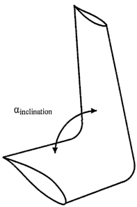
Fig. 1 illustrates the inclination of the winglet to the blade,
Fig. 2 illustrates the winglet height, the winglet root chord, the winglet tip
chord, the leading edge displacement and the trailing edge displacement,
Fig. 3 illustrates the winglet angle of attack,
Fig. 4 shows a preferred combined radius specific solidity of the outer 10% of
a
wing turbine rotor having a 1% winglet height,
Fig. 5 shows a preferred combined radius specific solidity of the outer 10% of
a
wing turbine rotor having a 2% winglet height, and
Fig. 6 shows a preferred combined radius specific solidity of the outer 10% of
a
wing turbine rotor having a 4% winglet height.
DETAILED DESCRIPTION OF TERMS AND EMBODIMENTS
In Fig. 1, the tip end of a blade is shown as seen in perspective with the
winglet
pointing upwards, and the inclination of the winglet to the blade is shown as
the
winglet inclination angle to blade, ainclination, defined as the angle between
the main
wing centre line and the winglet centre line.
CA 02673544 2009-06-22
WO 2008/077403 PCT/DK2007/000559
In Fig. 2 the tip end of a blade is shown as seen from the end thereof, i.e.
the blade
itself extends away from the viewer of Fig. 3. The winglet height, Xheight, is
defined
as the distance from the main wing chord line at the very tip to the chord
line of the
very tip of the winglet. The winglet root chord, Xrootchord, is defined as the
distance
5 from the leading edge to the trailing edge of the main wing at the very tip
where the
winglet is attached. The winglet tip chord, Xtipchord, is defined as the
distance from the
leading edge to the trailing edge of the winglet at the very tip of the
winglet. The
winglet leading edge displacement, XLED, is defined as the distance from the
leading
edge of the main wing at the very tip to the leading edge of the winglet at
very tip of
10 the winglet. The winglet trailing edge displacement, XTED, is defined as
the distance
from the trailing edge of the main wing at the very tip to the trailing edge
of the
winglet at very tip of the winglet.
In Fig. 3 the tip end of a blade is shown as seen from the side to which the
winglet tip
points, i.e. the tip of the winglet of Fig. 3 points towards the viewer. The
winglet
angle of attack, aAoA, is defined as the angle between the line parallel to
the main
wing chord plane at the tip and the winglet root chord plane
Modifying the blade with different winglets has shown to increase the
efficiency of
the rotor i.e. the amount of energy that the rotor extracts from the wind.
The annual increase in production for a turbine with an average wind speed of
8.5
m/s for a standard wind turbine rotor has been calculated theoretically for
various
extensions of the winglet:
original 1 % Winglet 2 % Winglet 4 % Winglet
Percent increase in annual production 0.0 0.9 1.5 2.4
for an average wind speed of 8.5 m/s
It is observed that the main effect of the blade design according to the
invention arise
for wind speeds between 5 - 11 m/s. This is highly advantageous, as for higher
wind
CA 02673544 2009-06-22
WO 2008/077403 PCT/DK2007/000559
11
speed, the maximum production is already reached and for smaller wind speeds,
radial movement of the wind has limited effect. It appears that the increase
tends to
be larger for larger heights of the winglets, but a practical limit with
respect to
mechanical construction and forces on the tip part of the blades due to the
presence
of the winglet is about 5% of the radius of the wind turbine.
The combined radius specific solidity of the outer 10% of wind turbine blades
has
been calculated for three different examples of blade designs according to the
present
invention and are shown in Figs. 4-6.
In Fig. 4, a design with a winglet height of 1% of the rotor radius is shown.
The
combined radius specific solidity (Sol,) of the rotor at the tip end of the
blades
immediately adjacent the winglet is chosen to be 0.00435 which results in a
constant
C = -0.00355 for the above formula. For a 3-bladed wind turbine with a rotor
diameter of 90 meter this equals a winglet height of 45 cm, a tip chord length
of
about 41 cm and a chord length at radius r = 90% of the rotor radius of 45
meter of
about 92 cm.
In Fig. 5, a design with a winglet height of 2% of the rotor radius is shown.
The
combined radius specific solidity (Sol,) of the rotor at the tip end of the
blades
immediately adjacent the winglet is chosen to be 0.0057 which results in a
constant C
-0.003085 for the above formula. For a 3-bladed wind turbine with a rotor
diameter
of 90 meter this equals a winglet height of 90 cm, a tip chord length of about
54 cm
and a chord length at radius r = 90% of the rotor radius of 45 meter of about
98 cm.
In Fig. 6, a design with a winglet height of 4% of the rotor radius is shown.
The
combined radius specific solidity (Solr) of the rotor at the tip end of the
blades
immediately adjacent the winglet is chosen to be 0.0057 which results in a
constant C
_ -0.003212 for the above formula. For a 3-bladed wind turbine with a rotor
diameter
CA 02673544 2009-06-22
WO 2008/077403 PCT/DK2007/000559
12
of 90 meter this equals a winglet height of 180 cm, a tip chord length of
about 62 cm
and a chord length at radius r = 90% of the rotor radius of 45 meter of about
107 cm.