Note: Descriptions are shown in the official language in which they were submitted.
CA 02674330 2009-07-02
R
PMHA-09006-PCT
DESCRIPTION
AIR POLLUTION CONTROL APPARATUS AND AIR POLLUTION CONTROL
METHOD
TECHNICAL FIELD
[0001] The present invention relates to an air pollution
control apparatus and an air pollution control method.
BACKGROUND ART
[0002] Fig. 5 is a schematic diagram of an air pollution
control apparatus of a coal combustion boiler. As shown in
Fig. 5, combustion gas 11 generates steam in a generating
tube within a furnace 12 of a coal combustion boiler 10
(the generated steam is separated into gas and liquid by a
steam drum 13, the steam is guided into a super heater 14
and becomes overheated steam, the steam is used for driving
a steam turbine, and then condensed water is circulated
into a water tube in the furnace 12 and is again
evaporated). The steam is overheated by the super heater
14 to heat water to be supplied to the coal combustion
boiler 10 in an economizer 15, and then the steam is
discharged from an exit of the economizer 15 as flue gas 16.
The flue gas 16 from the economizer 15 is supplied to a
denitrator 17, heats air 19 by heat exchange in an air
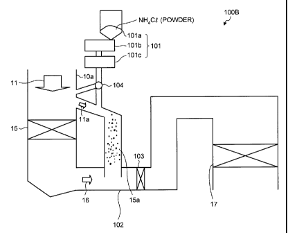
heater 18, is supplied to a dust collector 20, is further
supplied to a desulfurizer 21, and then is discharged to
atmosphere as purge gas 22.
[0003] As the denitrator 17, one is proposed which
sprays ammonium (NH3) to the flue gas 16 from the coal
combustion boiler 10 upstream of the denitrator (catalyst
unit), thereby reducing and denitrating the flue gas 16.
To reduce mercury included in flue gas, a system is
proposed that sprays a chlorinating agent such as HC1
1
CA 02674330 2009-07-02
28964-169
upstream of the denitrator 17, oxidizes (chlorinates) the
mercury on a catalyst, and reduces the mercury by a wet
desulfurizer installed downstream (Patent Document 1).
[0004] Patent Document 1: Japanese Patent Application
Laid-open No. H10-230137
[0005] In a power plant where a boiler device is
installed, it is necessary to strictly store ammonia and
HC1 as hazardous materials, and further HC1 has high
corrosiveness_ Therefore, there is a problem that high
costs are needed to manage these materials and to take
measures against corrosiveness.
To supply NH3 and HCl into a flue, a vaporizer and a
spray grid are required for each of them to enhance the
supply efficiency.
High-temperature heat source and steam are also
required to evaporate HC1.
[0006] The advent of an air pollution control apparatus
capable of easy storage, in which efficiency in removing
nitrogen oxides and mercury is not deteriorated is desired
as measures for flue gas.
[0007] In view of the above problem, it is an object of some
einbodiments of the present invention to provide an air pollution control
apparatus and an air pollution control method capable of
easy storage, in which the efficiency in removing nitrogen
oxides and mercury is not deteriorated, as the measure.s for
flue gas.
SUMMARY OF THE INVENTION
[U008] According to an aspect of the present invention,
an air pollution control apparatus that reduces nitrogen
oxides and oxidizes mercury in flue gas from a boiler by
using an ammonia denitrating catalyst includes: an
2
28964-169 CA 02674330 2009-07-02
ammonium-chloride supply unit that supplies powdery
ammonium chloride to a location near an entrance of an
economizer provided in a flue of the boiler or to an
economizer bypassing unit, or both of them. The supplied
powdery ammonium chloride is sublimated by combustion gas,
and hydrogen chloride and ammonium are supplied into the
flue_
[0009] In some embodiments of the air pollution control
apparatus, a particle diameter of the powdery ammonium
chloride is 0.25 millimeter or less.
[0010] In some embodiments of the air pollution control
apparatus, any one of an HCl supply unit and an NH3 supply
unit, or both of them are provided downstream of the
economizer.
[0011] In some embodiments of the air pollution control
apparat.u~, the ammonium chloride supply unit includes a
crushing unit that crushes solid ammonium chloride.
[0012] In some embodiments, the air pollution control
apparatus further includes a vaporizer that heats and
vaporizes the ammonium chloride supplied from the ammonium-
chloride supply unit.
[0013] In some embodiments, the air pollution control
apparatus further includes a vaporizer that heats and
vaporizes the ammonium-chloride supplied from the ammonium-
chloride supply unit, and a particle diameter of the
powdery ammonium chloride is 0.25 millimeter or less.
[0014] According to another 'aspect of the present
invention, an air pollution control method for reducing
nitrogen oxides and oxidizing mercury in flue gas from a
boiler by using an ammonia denitrating catalyst includes:
supplying powdery ammonium chloride to a location near an
entrance of an economizer provided in a flue of a boiler or
to an economizer bypassing unit, or both of them;
3
CA 02674330 2009-07-02
28964-169
sublimating the ammonium chloride in an atmosphere at a
temperature of combustion gas at a supply location; and
supplying hydrogen chloride and ammonium into the flue.
[0015] According to some embodiments of the present invention,
in the economizer or its bypassing unit of a boiler device through
which high-temperature combustion gas passes, HC1 and NH3
are vaporized by the high-temperature (550 to 650 C)
combustion gas by adding the powdery ammonium chloride
(NH4C1). With this configuration, it is possible to omit
the vaporizer, the steam grid, and the storage tank in
which liquid HC1 and NH3 are stored, which are used in the
conventional technique.
BRIEF DESCRIPTION OF DRAWINGS
[0016] [Fig. 1] Fig. 1 is a schematic diagram of an air
pollution control apparatus according to a first embodiment
of the present invention.
[Fig. 2] Fig. 2 is a schematic diagram of another air
pollution control apparatus according to the first
embodiment.
[Fig. 3] Fig. 3 is a schematic diagram of an air pollution
control apparatus according to a second embodiment of the
present invention.
[Fig. 4] Fig. 4 is a schematic diagram of an air pollution
control apparatus according to a third embodiment of the
present invention.
[Fig. 5] Fig. 5 is a schematic diagram of an air pollution
control apparatus of a coal combustion boiler.
EXPLANATIONS OF LETTERS OR NUMERALS
[0017] 10 coal combustion boiler
11, lla combustion gas
12 furnace
13 steam drum
4
CA 02674330 2009-07-02
PMHA-09006-PCT
14 super heater
15 economizer
15a economizer bypassing unit
16 flue gas
17 denitrator
BEST MODE(S) FOR CARRYING OUT THE INVENTION
[0018] The present invention is explained below in
detail with reference to the accompanying drawings. The
present invention is not limited thereto. In addition,
constituent elements in the following embodiments include
those that can be easily assumed by those skilled in the
art or that are substantially equivalent.
First Embodiment
[0019] An air pollution control apparatus according to a
first embodiment of the present invention will be explained
with reference to the drawings.
Fig. 1 is a schematic diagram of the air pollution
control apparatus according to the first embodiment. In
Fig. 1, the boiler system shown in Fig. 5 and a boiler
system of the present invention are the same, and Fig. 1
depicts only a portion from a boiler to a denitrator. Like
members are denoted by like reference numerals, and
explanations thereof will be omitted.
As shown in Fig. 1, an air pollution control apparatus
100A according to the first embodiment reduces nitrogen
oxides and mercury in the flue gas 16 discharged from a
boiler (not shown) by an ammonia denitrating catalyst. The
air pollution control apparatus 100A includes an economizer
bypassing unit 15a that diverts high-temperature combustion
gas 11 to a downstream side while bypassing the economizer
15 provided in a gas flue 10a for the combustion gas 11
from the boiler, provided with an ammonium-chloride supply
unit 101 that supplies powdery ammonium chloride (NH4C1) to
5
CA 02674330 2009-07-02
PMHA-09006-PCT
the economizer bypassing unit 15a. The air pollution
control apparatus 100A sublimates the ammonium chloride in
an atmosphere at a high temperature of the combustion gas
11, and supplies hydrogen chloride and ammonium into a flue
102.
Reference numeral 103 denotes a mixer that mixes
hydrogen chloride (HC1) and ammonium (NH3) supplied into
the flue gas 16.
[0020] With this configuration, NH4C1 powder is sprayed
to the economizer bypassing unit 15a, sublimated by high-
temperature combustion gas lla (550 to 650 C) that passes
through the economizer bypassing unit 15a, and supplied as
HCl and NH3 to the flue 102 for the flue gas 16 with which
the bypassing unit is in communication.
[0021] In the boiler device, concentration of nitrogen
oxides is varied. In such a case, urea ((HzN)2C=O) can be
sprayed together with ammonium chloride to increase the
supply of ammonia.
[0022] In the first embodiment, the ammonium-chloride
supply unit 101 that supplies the ammonium chloride (NH4C1)
into the economizer bypassing unit 15a includes a silo lOla
that temporarily stores the powdery ammonium chloride
therein, a feeder lOlb that supplies the stored ammonium
chloride to a crusher 101c by a predetermined amount, and
the crusher lOlc that crushes the supplied ammonium
chloride into a predetermined particle diameter.
[0023] Because the sublimation of NH4C1 is an
endothermic reaction, it is preferable that the temperature
is higher. Thus, in the first embodiment, at the same time
the NH4C1 powder is supplied from the silo lOla by the
feeder lOlb, the crusher 101c is connected to crush the
powder into fine particles so that the particles can easily
be sublimated. The supply amount can be adjusted by the
6
CA 02674330 2009-07-02
PMHA-09006-PCT
feeder lOlb, and controlled by an exit NOx monitor or Hg
monitor. When the powdery ammonium chloride has the
predetermined particle diameter or less, it is unnecessary
to install the crusher lOlc.
[0024] Because the predetermined particle diameter of
the ammonium chloride relates to a gas flow rate of the
combustion gas 11, it is necessary to determine the
predetermined particle diameter according to the flow rate.
For example, when a residence time of the combustion gas
lla that passes through the economizer bypassing unit 15a
is five seconds or less, it is preferable that the particle
diameter of the ammonium chloride is 0.25 millimeter or
less, and more preferably 0.2 millimeter or less.
[0025] NH3 decomposed by the ammonium chloride is used
for reducing and denitrating NOx by the denitrator 17, and
HCl is used for oxidizing mercury, thereby reducing
nitrogen oxides and mercury from the flue gas. The
ammonium chloride can be charged into the boiler with a
high temperature. However, because there is a possibility
that NH3 is decomposed when the temperature is equal to or
higher than its spontaneous ignition temperature of 651 C,
it is necessary that the temperature thereof be 650 C or
lower.
[0026] As shown with an air pollution control apparatus
100B in Fig. 2, the powdery ammonium chloride can be
supplied to a location close to an entrance of the
economizer 15.
A switching unit 104 is provided so that the powdery
ammonium chloride can be appropriately supplied to any one
of the location close to the entrance of the economizer 15
and the economizer bypassing unit 15a, or both thereof.
For example, when the residence time of the combustion
gas 11 passing through the economizer 15 is two seconds or
7
CA 02674330 2009-07-02
PMHA-09006-PCT
less, it is preferable that the particle diameter of the
ammonium chloride be 0.15 millimeter or less, and more
preferably 0.1 millimeter or less.
[0027] The concentrations of NH3 and HC1 in the flue 102
for the flue gas 16 are set such that a NH3/NOx molar ratio
with respect to an NOx concentration of the flue gas 16
becomes 1 or less according to required denitration
performance, and NH3 and HCl can be sprayed such that the
concentrations become several tens to several hundreds ppm,
preferably several tens to 200 ppm.
[0028] The amount of the combustion gas 11 that passes
through the economizer bypassing unit 15a is usually about
several percent of the entire combustion gas 11. Therefore,
it is preferable that the concentrations of NH3 and HC1 in
the economizer bypassing unit 15a is in a range of about
0.1 to several percent. This is because, when the
concentrations are so high, the cost is increased and the
cost efficiency is deteriorated. It is preferable that the
Hg concentration of the flue gas be in a range of 0.1 to
several tens g/m3N, and is 1/1000 or less in the molar
ratio with respect to the HCl concentration in the flue gas.
[0029] In the economizer bypassing unit 15a of the
boiler device through which the high-temperature combustion
gas 11 upstream of the denitrator 17 having the ammonia
denitrating catalyst passes, HC1 and NH3 are vaporized by
the high-temperature (550 to 650 C) combustion gas 11 that
passes through the economizer bypassing unit 15a by adding
the powdery ammonium chloride (NH4C1). Therefore, the
vaporizer, the spray grid, and the storage tank that stores
therein liquid HC1 and NH3 can be omitted, unlike the
conventional technique.
[0030] As described above, according to the present
invention, the HC1 and NH3 vaporizer, the spray grid and
8
CA 02674330 2009-07-02
PMHA-09006-PCT
the storage tank can be omitted. In addition, because the
powdery ammonium chloride (NHqCl) is neutral salt and it is
easy to handle the neutral salt, it is possible to largely
reduce the costs required for legal permission and
authorization for HC1 and NH3 which are both hazardous
materials, as well as the plant cost concerning safety
management measures.
[0031] Because the combustion gas lla that passes
through the economizer bypassing unit 15a is used as a heat
source for sublimation, another heat source is unnecessary.
Because the temperature is higher (550 C) than the
temperature of a denitrating catalyst (350 to 420 C) near
upstream of the conventional denitrating catalyst apparatus,
the sublimation rate is high, the required residence time
can be shortened and thus, any additional sublimation
equipment is not necessary.
[0032] Because the sublimation rate can be further
increased by crushing the ammonium chloride powder using
the crusher lOlc as needed, it is possible to prevent non-
sublimated ammonium chloride from remaining or accumulating.
[0033] It is less expensive to supply the ammonium
chloride alone as compared with the agent costs of HC1 and
NH3, which are separately supplied in the conventional
technique, and the operation cost for a long term can be
reduced.
Second Embodiment
[0034] An air pollution control apparatus according to a
second embodiment of the present invention will be
explained with reference to the drawings.
Fig. 3 is a schematic diagram of the air pollution
control apparatus according to the second embodiment. The
same members as those of the air pollution control
apparatus shown in Fig. 1 are denoted by the same reference
9
CA 02674330 2009-07-02
PMHA-09006-PCT
numerals, and explanations thereof will be omitted.
As shown in Fig. 3, an air pollution control apparatus
100C according to the second embodiment includes an HC1
supply unit 111 that supplies HCl and an NH3 supply unit
112 that supplies NH3, to the flue 102 for the flue gas 16.
[0035] When the balance of the concentrations of
nitrogen oxides and mercury in the flue gas discharged from
a combustion device such as a boiler is different from a
normal balance, a necessary amount of hydrochloric acid or
ammonium is supplied into the flue 102 to respond to the
balance.
For example, when necessary HC1 is greater than
necessary NH3, HC1 is sprayed from the HC1 supply unit 111
and the ammonium chloride is sprayed.
[0036] On the other hand, when the necessary NH3 is
smaller than the necessary HC1, NH3 is sprayed from the NH3
supply unit 112 and the ammonium chloride is sprayed.
At this time, urea ((H2N)2C=0) can be sprayed instead
of ammonia.
[0037] With this configuration, because ammonia and
hydrogen chloride are separately supplied in the second
embodiment, even if the concentration of nitrogen oxides or
mercury in the flue gas 16 is varied, an appropriate
operation can be taken.
Third Embodiment
[0038] An air pollution control apparatus according to a
third embodiment of the present invention will be explained
with reference to the drawings.
Fig. 4 is a schematic diagram of the air pollution
control apparatus according to the third embodiment. The
same members as those of the air pollution control
apparatus shown in Figs. 1 and 3 are denoted by the same
reference numerals, and explanations thereof will be
CA 02674330 2009-07-02
28964-169
omitted.
As shown in Fig. 4, an air pollution control apparatus
100D according to the third embodiment includes a rotary
dryer (or rotary kiln) 120 as an evaporation unit that
heats and evaporates the ammonium chloride supplied by the
feeder lOlb, for example.
[0039] Because the rotary dryer 120 is provided, the
heating and evaporating operations for NH4C1 are
facilitated, and it is possible to reliably sublimate and
supply HC1 and NH3 into the flue.
The sublimation step can be divided into two steps by
using the rotary dryer 120 in this manner, and it is
possible to more reliably vaporize the ammonium chloride,
and to reliably prevent the powder from remaining.
[0040] [Test Examples 1 to 4]
Tests were conducted using the air pollution control
apparatus 100C shown in Fig. 3.
The amount of the combustion gas 11 from the boiler
furnace is 2,400,000 Nm3/h, the temperature of the
combustion gas 11 at the entrance of the economizer is
600 C, and 24,000 Nm3/h corresponding to 1% of the combustion
gas 11 is diverted into the economizer bypassing unit 15a.
[0041] <Test Example 1>
In a test example 1, an NOx concentration at the
entrance of the denitrator (SCR) 17 is 167 ppm, and a
mercury concentration (Hg ) is 8 g/m3N.
By supplying the powdery ammonium chloride by 875 kg/h,
an NH3 supply concentration at the entrance of the
denitrator (SCR) 17 is 150 ppm, an HCl supply concentration
at the entrance of the denitrator (SCR) 17 is 150 ppm, the
denitration ratio is 90%, and a mercury oxidation ratio is
97 0 .
[0042] These results are shown in Table 1.
11
CA 02674330 2009-07-02
PMHA-09006-PCT
[Table 1]
Test Test Test Test
example 1 example 2 example 3 example 4
Flue gas amount M N/ 2,400,000 2,400,000 2,400,000 2,400,000
h
Flue gas Co 600 600 600 600
temperature at
economizer
entrance
Amount of gas M N/ 24,000 24,000 24,000 24,000
bypassing h
economizer
NH4C1 supply Kg/h 875 875 875 420
amount
NH3 supply amount Kg/h 0 319 0 0
Urea supply amount Kg/h 0 0 530 0
HC1 supply amount Kg/h 0 0 0 304
NH3 concentration Ppm 150 315 315 72
at entrance of
denitrator
HC1 concentration Ppm 150 150 150 150
at entrance of
denitrator
NOx concentration Ppm 167 350 350 80
at entrance of
denitrator
NH3/NOx ratio - 0.9 0.9 0.9 0.9
Temperature at Co 370 370 370 370
entrance of
denitrator
Hg concentration g/ 8 8 8 8
at entrance of m3N
denitrator
Hg + concentration g/ 2 2 2 2
at entrance of m3N
denitrator
Hg concentration g/ 0.24 0.4 0.4 0.16
at exit of m3N
denitrator
Hg + concentration g/ 9.76 9.6 9.6 9.84
at exit of m3N
denitrator
Hg oxidation % 97 95 95 98
ratio
Denitration ratio % 90 90 90 90
[0043] <Test Example 2>
In a test example 2, the NOx concentration at the
12
CA 02674330 2009-07-02
PMHA-09006-PCT
entrance of the denitrator (SCR) 17 is increased as high as
350 ppm. The mercury concentration (Hg ) is the same and
is 8 g/m3N.
When the powdery ammonium chloride is supplied by 875
kg/h and ammonia is supplied into the flue 102 by 319 kg/h,
the NH3 supply concentration at the entrance of the
denitrator (SCR) 17 became 315 ppm, the HCl supply
concentration at the entrance of the denitrator (SCR) 17
became 150 ppm, the denitration ratio is 90%, and the
mercury oxidation ratio is 95%.
In the test example 2, because the nitrogen oxides
concentration is high, the mercy oxidation ratio is
slightly reduced.
[0044] <Test Example 3>
In a test example 3, the NOx concentration at the
entrance of the denitrator (SCR) 17 is increased as high as
350 ppm. The mercury concentration (Hg ) is the same and
is 8 g /m3N N.
The powdery ammonium chloride is supplied by 875 kg/h,
and urea is supplied into the flue gas flue 102 by 530 kg/h.
With this configuration, the NH3 supply concentration at
the entrance of the denitrator (SCR) 17 became 315 ppm, the
HC1 supply concentration at the entrance of the denitrator
(SCR) 17 became 150 ppm, the denitration ratio is 90%, and
the mercury oxidation ratio is 95%.
Even if the urea is supplied instead of separately
supplying the ammonia, the denitration ratio is not reduced.
In the test example 3 also, because the concentration of
nitrogen oxides is high, the mercury oxidation ratio was
slightly reduced.
[0045] <Test Example 4>
In a test example 4, the NOx concentration at the
entrance of the denitrator (SCR) 17 is reduced as low as 80
13
CA 02674330 2009-07-02
PMHA-09006-PCT
ppm. The mercury concentration (Hg ) is the same and is 8
g/m3N .
The powdery ammonium chloride is supplied by 420 kg/h
and HC1 is supplied by 304 kg/h. With this configuration,
the NH3 supply concentration at the entrance of the
denitrator (SCR) 17 became 72 ppm, the HC1 supply
concentration at the entrance of the denitrator (SCR) 17
became 150 ppm, the denitration ratio is 90%, and the
mercury oxidation ratio is 98%.
In the test example 4, because the nitrogen oxides
concentration is low, the mercury oxidation ratio is
enhanced.
INDUSTRIAL APPLICABILITY
[0046] By adding the powdery ammonium chloride (NH9C1)
according to the present invention as described above, HC1
and NH3 are evaporated by high-temperature (550 to 650 C)
combustion gas passing through the economizer or the
economizer bypassing unit. With this configuration,
omission of constituent elements in air pollution control
apparatus can be achieved.
14