Note: Descriptions are shown in the official language in which they were submitted.
CA 02681685 2014-04-01
CONTAINER SEAL WITH REMOVAL TAB AND
HOLOGRAPHIC SECURITY RING SEAL
BACKGROUND OF THE INVENTION
FIELD OF THE INVENTION
[0001] The invention relates generally to a laminated sealing member for
closing the mouth of a container, the sealing member having a graspable tab on
its
upper surface to expedite its removal from the container, and the sealing
member also
having a holographic security seal layer.
DESCRIPTION OF THE RELATED ART
[0002] In the figures, the first digit of the reference numbers correspond to
the figure number. The remaining two digits of the reference numbers for
elements
within the various figures that correspond to each other always match. Hence,
the
bottom hot melt adhesive layer, which is essentially same in all of the
figures, is
assigned the reference number 122 in Figure 1, 222 in Figure 2, 322 in Figure
3, and
422 in Figure 4.
[0003] It is often desirable to seal a bottle, jar, or other container having
a
screw-on cap by providing a sealing member that attaches across the mouth of
the
container before the cap is screwed down onto the container for the first
time. When
the cap is later removed after purchase, the purchaser must penetrate, break,
or
otherwise remove the sealing member before the contents of the container may
be
accessed. The cap may then be screwed back into place to keep the contents
fresh and
to keep the contents from spilling out. If the sealing member is not present
when the
container is first opened, or if it is damaged, then the purchaser knows that
the
contents of the container may have been tampered with. And as an anti-
1
CA 02681685 2009-09-22
WO 2008/118570
PCT/US2008/054383
counterfeiting measure, such a sealing member may include a hologram visible
to the
purchaser after the cap is removed, the pattern of the hologram being a unique
identifier of a particular manufacturer.
[0004] Many sealing members are known which have tabs attached to their
upper surface to facilitate their removal. One simply grasps the tab and pulls
it to
one side, and the entire sealing member is removed from the container in a
single
motion.
[0005] U.S. Patent No. 5,514,442, which issued to Michael P. Galda, et al.
on May 7, 1996 discloses the sealing member 100 shown, in a side cross-
sectional
view, in Figure 1 (which is derived from Figure 4 of the '442 patent). (For
clarity,
the cross sectioning lines have been omitted from the layers 102, 104, and 110
in
Figure 1 and are shown in the urethane adhesive layers 114 and 116 and hot
melt
bonding material or adhesive layer 122.) The sealing member 100 is a laminated
structure the lower half of which is formed from an aluminium foil layer 110
the
1 5 underside of which is bonded to a hot melt bonding material or adhesive
layer 122.
The upper half of the sealing member 100 is formed from a sheet of bleached
kraft
paper 102 the lower half of which is glued to a polyester layer 104 (most
likely a
sheet or film of PET, or Polyethylene Terephthalate). As shown, the upper and
lower
halves of the sealing member 100 are joined by means of an adhesive layer 116
which extends only half way (left-to-center) and which joins the aluminium
foil layer
110 to the polyester layer 104, leaving a gap 124 to the right. The sealing
member
100 is circular and is die-cut from a much larger sheet of laminated
materials, the
cutting being positioned to cause the gap 124 to be present in each sealing
member
100, thereby forming a removal tab that comprises the kraft paper 102 and the
polyester 104 layer above the gap 124 to the right in Figure 1. The '442
patent
teaches that this circular sealing member 100 is inserted deep into a screw-on
cap
(not shown) which is then screwed onto a container (not shown). Induction
heating
applied to the neck of the container then heats up the aluminium foil layer
110,
causing the hot melt bonding material or adhesive layer 122 to melt and
thereby seal
the sealing member 100 to the top of the container. After the container is
purchased,
2
CA 02681685 2014-04-01
the purchaser removes the cap and then grasps and pulls on the removal tab and
thereby removes the sealing member 100 from the container.
[0006] U.S. Patent No. 6,866,926, which issued to Joe Smelko et al on
March 15, 2005, teaches the design of an improved sealing member 200 which is
shown, in a side cross-sectional view, in Figure 2 ((which corresponds to
Figure 3 of
the '926 patent). (For clarity, the cross-sectional lines have been omitted
from the
layers 202, 204, 206, 208, 210, and 212 in Figure 2 and are shown in the
urethane
adhesive layers 218 and 220 and hot melt bonding material or adhesive layer
222.)
The upper layers of the sealing member 200 comprise an upper PET layer 202
bonded to a lower EVA (ethylene-vinyl acetate) layer 204. The lower layers
comprise an aluminium foil layer 210 which is bonded to a PET layer 212 which
in
turn is bonded to a hot melt bonding material or adhesive layer 222. This
design
adds a PE (polyethylene) foam layer 208 over the upper surface of the
aluminium
foil layer 210, as is illustrated in Figure 2 (which corresponds to Figure 3
of the '926
patent). The EVA layer 204 is heat bonded to the new PE foam layer 208 in the
left
half of the sealing member 200, as is shown. To the right, a release strip
206, made
of PET, is coated on its underside with a silicon release coating to prevent
the strip
206 from sticking to the PE foam layer 208. The PET release strip 206 and the
PET
upper layer 202 sandwich the left half of the EVA layer 204 to a release tab.
The
EVA layer 204 and the PE foam layer 208 are heat bonded together.
[0007] Several patents teach the incorporation of holographic film into
various types of seals for packages and containers. Such holographic sealing
members enable counterfeit products to be identified and also signal, by their
condition when the seals have previously been tampered with.
[0008] Once such Holographic seal is disclosed in U.S. Patent No.
5,319,475, which issued to Ralph Kay, et al. on June 7, 1994. This patent
discloses a
package sealing tape having a layered structure. Its upper layer is a
removable layer
formed from polypropylene or polyester film, smooth and transparent. This
upper
layer is loosely adhered (by means of wax or corona discharge treatment) to a
much
thinner, transparent polymer layer. The polymer layer is bonded to an
embossable
lacquer layer formed from non-cross-linkable polyurethane or polyester. This
layer
3
CA 02681685 2009-09-22
WO 2008/118570
PCT/US2008/054383
is embossed to define a hologram, and then a metallic film, such as aluminum,
is
deposited upon this layer and is optionally coated with a polymeric coating.
The
lowest layer is a pressure sensitive transfer adhesive bound to release paper.
In use,
the release paper is removed, and then the tape is used to seal a container.
The upper
layer is scuff resistant, so it may be left on during transit to protect the
hologram. It
may also be removed. In the face of solvents or heat, the embossable layer and
its
hologram is quickly and irreversibly damaged, thus making a permanent record
of
the attempt at tampering with the package. A similar arrangement is disclosed
in
U.S. Patent No. 6,659,507, issued to Michael Banahan, et al. on December 9,
2003,
which also provides an additional fluorescent pattern visible only under
ultraviolet
light and a mechanism that breaks up the hologram if the layers are separated.
[0009] U.S. Patent No. 7,012,032, which issued to Steven R. Consentino, et
al. on March 14, 2006, discloses in Figure 3 of the '302 patent a holographic
image
(col. 7, lines 20-34 of the '032 patent) applied as the top layer in a
laminated sealing
1 5 member for a "bottle type container" with an upper PET layer, an
intermediate
thermal bonding polymer layer (a co polyester resin), and a lower woven or non-
woven reinforcing scrim polymer layer (polyester such as PET) beneath which is
an
adhesive layer. In its "Background" portion, the '302 patent says: "seals and
lids can
be constructed to have a tab that extends outwardly from the periphery of the
seal so
that a user can grasp the tap to aid in removing the seal from the container."
('032
patent, col. 1, lines 37-40) Figure 3 of the '032 patent discloses a tab 33
that is
somehow attached to, and extending outwards from, the periphery of the lowest
adhesive layer. The text accompanying this figure says: "Preferably the seal
contains a small tab to facilitate removal." Nothing more is said about this
tab.
[0010] U.S. Patent No. 4,892,209, which issued to Jan L. Dorfinan, et al. on
January 9, 1990, discloses a liquor bottle capping assembly which includes a
sealing
member that comprises two parts: First, a lower circular disk, made of
aluminum or
"high durometer plastic" or some other material sufficiently strong to resist
and/or
provide evidence of penetration by a hypodermic needle; and second, an upper
circular sheet member 26 that is adhesively laminated to the lower circular
disk 60.
The upper circular sheet member may be made of metal foil and may carry a
laser-
4
CA 02681685 2009-09-22
WO 2008/118570
PCT/US2008/054383
imprinted hologram obtained from American Bank Note Holographics, Inc.
Alternatively, the circular disk 80 may be constructed from plastic film,
metallised
plastic, or some other material that will provide evidence of any tampering.
The
upper circular sheet member initially has a figure-8 shape, and it is folded
back upon
itself to form joined upper and lower circular portions, the lower circular
portion
forming the circular sheet member itself, and the upper circular portion
forming a
removal tab of slightly smaller diameter, as is illustrated in Figures 1 and 2
of the
'209 patent.
SUMMARY OF THE INVENTION
100111 Briefly summarized, the present invention relates to a holographic
sealing member for a container designed for attachment to the rim of an
opening in
the container. The sealing member comprises a holographic layer having an
upper
plastic layer on its upper side and a lower embossed image layer on its lower
side,
having a sealant or adhesive layer attached to at least those portions of the
lower side
of the holographic layer that are intended to come into direct contact with
the
container's rim when the sealing member is placed upon and is sealed to the
container, and having a metal foil layer over and covering and adhesively
bonded to
the upper side of the holographic layer that may be inductively heated to
actuate the
heat actuated sealant. A tab covers and is adhesively bonded to the metal foil
layer
and may be pulled to remove the sealing member from a container. After this
sealing
member is attached to a container, and when the tab is pulled to remove the
sealing
member from the container, almost the entire sealing member pulls away from
the
container, but those portions of the holographic layer's lower embossed image
layer
that are attached directly to the rim of the container by the sealant or
adhesive layer
remain attached to the rim of the container to form a hologram that runs
around the
container's rim.
5
CA 02681685 2009-09-22
WO 2008/118570
PCT/US2008/054383
BRIEF DESCRIPTION OF THE DRAWINGS
[0012] Figures 1 and 2 each present a cross-sectional side view of a prior-
art laminated sealing member having a removable tab structure facing to the
right.
The vertical dimensions are exaggerated and are not drawn in proportion to the
actual
vertical dimensions of each layer of the sealing member. (Cross-sectioning
lines are
omitted from some layers for clarity.)
[0013] Figure 3 presents a cross-sectional side view of a laminated sealing
member in accordance with an embodiment of the invention having a removable
tab
structure facing to the right, the sealing member shown attached to the mouth
of a
container. The vertical dimensions are exaggerated and are not drawn in
proportion
to the actual vertical dimensions of each layer of the sealing member. (Cross-
sectioning lines are omitted from some layers for clarity.)
[0014] Figure 4 presents a cross-sectional side view of the laminated
sealing member shown in Figure 3 following removal of the tab and the layers
1 5 attached to the tab, the lowermost layers of the sealing member shown
still attached
to the mouth of the container.
[0015] Figure 5 presents a cross-sectional side view of a laminated sealing
member in accordance with another embodiment of the invention having a
removable tab structure facing to the right. The vertical dimensions are
exaggerated
and are not drawn in proportion to the actual vertical dimensions of each
layer of the
sealing member. (Cross-sectioning lines are omitted from some layers for
clarity.)
DETAILED DESCRIPTION OF THE EMBODIMENTS
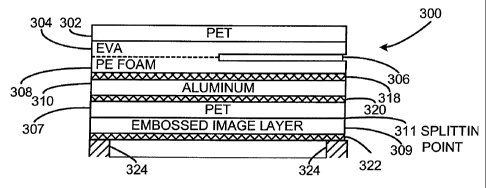
[0016] A sealing member 300 for a container 324 is designed in accordance
with a first embodiment of the present invention and is illustrated in Figures
3 and 4.
The immediately following paragraphs describe Figures 3 and 4. Later
paragraphs
describe Figure 5, which presents a related invention.
[0017] Figure 3 presents a side, cross-sectional view of the sealing member
300 and of the upper, circular rim of a PET container 324 to which the sealing
6
CA 02681685 2009-09-22
WO 2008/118570
PCT/US2008/054383
member 300 is sealed by induction heating of an aluminum layer 310, which
melts
the hot melt bonding material or adhesive layer 322 and binds the sealing
member
300 to the circular rim of the container 324. (Note that the cross sectioning
lines
have been omitted from the layers 302, 304, 308, 310, 307, and 309 in Figure 3
and
are shown in the urethane adhesive layers 318 and 320 and hot melt bonding
material
or adhesive layer 322.)
[0018] The structure of the sealing member 300 (Figure 3) is essentially the
same as that of the sealing member 200 (Figure 2 described above) except that
the
lower PET layer 212 in Figure 2 has been replaced in Figure 3 with a
holographic
film comprising a PET layer 307 bonded to a embossed image layer 309 which
bears
a holographic image and which has an aluminum substrate. The layer 309 in its
turn
is bonded by the hot melt bonding material or adhesive layer 322 to the land
area of
the container 324 (the land area of the container 324 is the uppermost, ring-
shaped
upper surface of the circular upper rim of the container 324). The PET layer
307 and
the embossed image layer 309 are bonded together in such a manner, and with
such a
bonding strength, that the layers 307 and 309 are separable along their
periphery ¨
the bond at a splitting point 311 is not as strong as the bond formed by the
layer 322
between the layer 309 and the container 324.
[0019] Accordingly, when the tab formed by the layers 302, 304, and 306 is
pulled, all of the uppermost layers 302, 304, 308, 310, and 307 of the sealing
member 300 are pulled away along with all save a thin peripheral ring of the
embossed image layer 309, leaving only a thin peripheral ring 309A (see Figure
4) of
the embossed image layer 309 sealed by means of a thin ring of the hot melt
bonding
material or sealing layer 322A to the land area of the container 324.
[0020] Accordingly, a circular ring of the embossed image layer 309A
remains bonded to the land area of the container 324 after the sealing member
300 is
removed. Thus, a thin ring of the hologram which the embossed image layer 309A
carries remains attached to the upper lip of the container 324, while the
remainder of
the embossed image layer 309 is peeled away and is removed from the container
324
and is separated from the circular ring portion 309A of the layer 309. Hence,
removal of the tab (formed by the layers 302, 304, and 306) necessarily
produces
7
CA 02681685 2009-09-22
WO 2008/118570
PCT/US2008/054383
destruction of the hologram such that the holographic seal borne by the
embossed
image layer 309 is torn through and can never be reassembled and reattached to
the
container 324.
[0021] The sealing member 300 is thus entirely removed in a single motion,
but the ring portion 309A of the embossed image layer 309 remains behind,
attached
to the land area of the container 324, torn away from the remainder of the
embossed
image layer 309 in a way that destroys the hologram and makes it impossible to
re-
seal the sealing member 300 back onto the container 324. After the sealing
member
300 is removed from the container 324, the holographic image is visible on the
top
side of the rim of the container 324. It is not possible to reseal the
container.
[0022] The bonding of the PET layer 307 to the embossed image layer 309
is carefully controlled to set the amount of adhesion that exists between the
PET
layer 307 and the embossed image layer 309. This bonding strength must be low
enough so that when force is applied to the tab formed by layers 302, 304, and
306,
1 5 the sealing member 300 splits at the splitting point 311 around the
periphery of the
sealing member 300 but only above the land area of the container 324, thus
permitting most of the embossed image layer 309 to be ripped away still
attached to
the layers 302, 304, 306, and 307 but leaving behind the ring portion 309A of
the
embossed image layer 309 attached to the land area of the container 324, as is
shown
in Figure 4. PET holographic film produced by American Bank Note Holographics
(ABNH) works well in this application. A product could be designed that would
function in the same manner if the holographic film was modified to contain
some
type of release layer between the PET film layer307 and the embossed image
layer
309. The PET film produced by ABNH has proved (in its normal, unmodified form)
to have a structure that functions properly.
[0023] The PET layer 307, the embossed image layer 309, and the bond
between them are preferably chosen to be relatively heat insensitive so that
overheating by inductive heating of the hot melt bonding material or adhesive
layer
322 does not adversely affect the amount of effort that is required to remove
the
sealing member 300. In conventional designs, such as that shown in Figure 2,
it is
the seal between the container (not shown in Figure 2) and the entire sealing
member
8
CA 02681685 2009-09-22
WO 2008/118570
PCT/US2008/054383
200 that must be broken, and the amount of effort that is required to remove
the
sealing member 200 can be adversely affected by overheating during the
inductive
heat sealing of the sealing member 200 to a container. The ABNH PET
holographic
film is relatively insensitive to heat variations, as is explained more fully
in a later
paragraph.
[0024] In another embodiment of the invention illustrated in Figures 3 and
4, two American Bank Note Holographics, Inc. films are included in the same
structure. The structure is the same as described in Figures 3 and 4 with the
addition
of a second holographic film that is laminated between the aluminum foil layer
310
and the holographic film layer (layers 307 and 309) which is coated with the
heat
actuated coating (the layer 322). In addition, gold pigmentation is added to
the
adhesive layer between the two holographic film layers. When separation of the
layer 322 and the metal and holographic embossed image layer 309 from the PET
layer is invoked upon removal of the sealing member 300, the holographic ring
309A
1 5 from the
primary holographic layer remains on the rim of the PET container 324, and
the uncovering of the area where this ring separates from the primary seal
exposes
the secondary holographic film that appears in gold because of the added
pigmentation. This leaves a portion of a holographic image on the container
rim and
another portion on the removed sealing member 300 components.
[0025] The heat activated hot melt bonding material or adhesive layer 322
in Figure 3 is a polyester heat seal coating 40-3 obtainable from Rohm and
Haas.
This heat actuated coating is applied to the metallic side of metallised
holographic
film (comprising the PET layer 307 and the embossed image layer 309 which
includes a metal layer formed from aluminum). The PET side (307) of the
holographic film is laminated and adhered to an aluminum foil layer 310. Above
this
foil layer 310 an optional insulating layer 308 (polyethylene foam in Figure
3, for
example) can be applied, and polyethylene, polypropylene, or polyester may be
applied above this insulating layer, or these materials may be applied
directly to the
foil layer if the optional insulating layer 308 is absent. A tab defining PET
release
strip 306 is placed over and covers at least a portion of the foil layer 310
or insulating
layer 308. An EVA or adhesive layer 304 lies above the PET release strip 206
and is
9
CA 02681685 2009-09-22
WO 2008/118570
PCT/US2008/054383
covered by a PET layer 302 to form the tab that is used to remove the sealing
member 300 from the rim of the container 324. The splitting or separation
point 311
occurs within the holographic film layer. Because the embossed image layer 309
is
thin and is bonded firmly to the rim of the container 324, in this case a PET
container
324 to coincide with the PET heat seal coating (the hot melt bonding material
or
adhesive layer 322), the upper liner is completely removed from the rim,
leaving the
PET heat seal coating layer 322A and the metal and image layer 309A only on
the
rim of the container 324. A strong bond is desired between the layer 322 and
the
upper lip of the container 324 to firmly attach the ring of embossed image
layer
309A to the upper lip of the container 324. Some other heat seal coating can
be
selected that can provide a seal to other types of containers ¨ for example, a
polypropylene heat seal coating or a polyethylene heat seal coating can be
used with
a container made of those materials. It may also prove feasible to extrusion
coat the
metal side of the holographic film with a suitable polymer film as thin as 0.5
mils
1 5 that would provide the desired splitting and adhesion in the rim area
of the container
324.
[0026] With reference to Figure 5, a different but related invention is
illustrated embodied in a sealing member 500. (Once again, the cross sectional
lines
are omitted from the layers 502, 504, 506, 508, 507, 509, and 510 in Figure 5
for
clarity and are shown in the urethane adhesive layers 516, and 518 and hot
melt
bonding material or adhesive layer 522.)
[0027] The sealing member 500 is also similar to the sealing member 200
shown in Figure 2, but the polyester foam layer 208 shown in Figure 2 is
replaced by
a white PET layer 508 that is bonded to a holographic film formed by the
combination of a PET layer 507 with an embossed image layer 509 that includes
a
metal (aluminum) layer, the layers 507 and 509 being bonded together in a
manner
such as to form a splitting point 511 that gives way then the layers 502, 504,
and 506
are pulled. The splitting point 511 is thus within the holographic film
structure,
between the image layer 509 and the PET layer 507. The urethane adhesive layer
518 binds the metal and embossed image layer 509 to the upper surface of the
adhesive coated (adhesive layer 522) aluminum foil layer 510. The adhesive
layer
CA 02681685 2009-09-22
WO 2008/118570
PCT/US2008/054383
522 is an easily punctured film such as MDPE (medium density polyethylene) 1.5
mils in thickness obtainable from Covalence Specialty Materials Corporation.
This
design allows the holographic embossed image layer 509 and aluminum film layer
510 to be destroyed easily by puncturing through these two layers. In this
design,
there is no PET acid barrier layer beneath the two layers 509 and 510, since
such a
layer would be difficult to penetrate with a finger. Other easily-punctured
films,
such as a NEX (a trademark of New England Extrusion, Inc.) sealant having an
EVA
content or SURLYN (a trademark of DuPont for a particular DuPont thermoplastic
ionomer resin product), etc., may be used to form the layer 522.
[0028] The strength of the bond between the layers 507 and 509 is chosen
to cause the sealing member 500 to split apart at 511 when the tab formed by
the
layers 506, 504, and 502 is pulled upwards and to the side. Accordingly, when
the
tab formed by the layers 506, 504, and 502 is pulled, the sealing member 500
splits
apart at the splitting point 511, uncovering the hologram which is visible in
the
1 5 embossed image layer 509 and leaving in place the seal formed by the
aluminum
layer 510 that is bonded to the embossed image layer 509.
[0029] After removing the upper layers 502, 504, 506, 508, and 507 of the
sealing member 500 by pulling on the tab formed by the layers 506, 504, and
502, an
individual wishing to access the container (not shown) must then pierce the
remaining layers 509 and 510, thus breaking the holographic seal over the
container.
Hence, the seal on the container cannot be broken without the simultaneous
destruction of the hologram.
[0030] This design again uses ABNH PET holographic film. The chemistry
of the image layer of this product supports heat resistance for the image. The
image
layer is highly cross-linked, and this gives the film superior heat resistance
and also
explains why the bond between the layers within the holographic film tend to
be
relatively weaker. Many holographic films do not have this heat resistance,
especially if the image is cast on a polypropylene film. Since induction
container
sealing can produce temperatures that can be in the range of 350 to 450
degrees
Centigrade, if the holographic film technology does not possess adequate heat
11
CA 02681685 2009-09-22
WO 2008/118570
PCT/US2008/054383
resistance, then the image or film or both would become distorted during
induction
heating, particularly when excessive heating is applied.
[0031] By removing, separating, or splitting the PET layer away from the
image layer, the image of the hologram remains undisturbed and completely
legible
above only an easily pierced layer of foil and sealant and can be destroyed by
simply
puncturing it with a finger. If the PET layer were not stripped away when the
tab
layers were pulled away, then the PET layer would need to have sufficient heat
stability, and it would also have to maintain the integrity of the image
layer. It would
be difficult to puncture through the lining of such a structure.
[0032] An alternative arrangement omits the white PET layer 508 and the
bonding material 516 and has the EVA layer 504 bonded directly to the PET
layer
507.
[0033] While several embodiments of the invention have been described,
numerous alternatives will occur to those skilled in the art. The claims
appended to
1 5 and forming a part of this patent application are intended to cover all
such
alternatives that fall within the true scope of the invention.
12