Note: Descriptions are shown in the official language in which they were submitted.
CA 02682816 2009-10-02
Specification
Spiral Steel Pile
Technical Field
[0001] The present invention relates to a foundation pile for the foundation
of a
building.
Background Art
[0002] As shown in FIG. 5, conventional foundation piles (2) used for the
foundation of
buildings are driven into the ground inside a shallow hole, and the head of
the
foundation pile, which sticks out from the ground, is covered with reinforced
concrete
with anchor bolts sticking out on top, and thus, the foundation (7) is
constructed and a
pillar for a building or the like can stand on the foundation.
[0003] A method for driving a pile using a hammer is generally used to build
conventional foundation piles, but this causes strong vibrations in the
ground, as well
as noise. As a result, residents in the neighborhood are bothered by vibration
and
noise.
Meanwhile, the present applicant proposed a spiral pile as a pile causing
little
vibration and noise when driven into the ground and made the product available
on the
market (see Patent Documents 1 to 4).
Patent Document 1: Japanese Unexamined Utility Model Publication S59 (1984)-
19639
Patent Document 2: Japanese Translation of International Unexamined Patent
Publication H10 (1998)-513237
Patent Document 3: Japanese Patent Application 2002-172089
Patent Document 4: Japanese Unexamined Patent Publication H10 (1998)-296342
[0004] However, conventional spiral piles generally have an outer diameter of
approximately 100 mm or less, and therefore, products are in such a form that
the
entirety of the pile is spiral or a spiral portion is inserted at the end of a
cylindrical pile.
However, the present inventor conducted diligent research, and as a result
found that
steel pipes used as foundation piles have an outer diameter of no less than
100 mm and
the resistance in the steel pipe portion when it is driven into the ground
becomes
greater than the force with which the spiral portion pulls the steel pipe, and
that it is
thus difficult for conventional piles in spiral form to be smoothly driven
into a
foundation. In some cases, a problem arises, such that the joint between the
steel pipe
portion and the spiral portion breaks.
1
CA 02682816 2009-10-02
Disclosure of the Invention
Problem to Be Solved by the Invention
[0005] An object of the present invention is to provide a new pile to replace
conventional
foundation piles, so that piles can be driven into the ground with little
vibration and
noise, and thus do not bother residents in the neighborhood, and in
particular, to
provide a spiral steel pipe pile that can be smoothly driven into the ground
even when
the outer diameter is more than 100 mm.
Means for Solving Problem
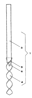
[0006] As shown in FIG. 1, a spiral steel pipe pile (1) is provided. This pile
is gained by
attaching a spiral portion (4) gained by twisting flat steel to a steel pipe
(3), which is a
conventional foundation pile (2). Specifically, it is a spiral steel pipe pile
having a steel
pipe (3), a spiral portion (4) gained by twisting flat steel having the same
or a greater
width than the outer diameter of the steel pipe, and a spiral slit (5) for
inserting the
spiral portion at the lower end of the steel pipe, characterized in that the
spiral portion
is inserted through the slit, and the steel pipe and the spiral portion are
welded
together in such a state that the two share the same center line, and a cover
(6) in
conical form is welded to the lower end of the steel pipe so that the hole in
the spiral
insertion portion is covered.
Here, the present applicant successfully developed technology for
manufacturing this spiral portion for the first time, and spiral portions are
currently
manufactured using a spiral manufacturing machine and sold (see Patent
Document 4).
[0007] Though conventional foundation piles are driven into the ground using a
hammer,
this spiral steel pipe pile is pressed into the ground while being rotated. As
a result,
there is little vibration and noise when the pile is driven into the ground.
[0008] The spiral steel pipe pile has another excellent feature. It has strong
resistance
against loads in the vertical direction.
The reason is as follows. Conventional foundation piles bear a load and
support the building in the vertical direction with a force of friction around
the surface
and a supporting force at the end.
In contrast, the spiral steel pipe pile has a spiral portion that is screwed
into
the ground, and thus has a strong resistance to loads in the vertical
direction, so that
the pile cannot be pushed in or pulled out unless the stratum around the pile
is broken.
Effects of the Invention
2
CA 02682816 2009-10-02
[0009] First, when a spiral steel pipe pile is used as described above, the
pile is driven
into the ground with little vibration and noise, and therefore does not bother
residents
in the neighborhood very much.
Second, the resistance to the load in the vertical direction is greater than
that
of conventional foundation piles, and the pile according to the invention has
excellent
resistance to loads, particularly in soft ground. Here, the resistance to the
load in the
horizontal direction is almost the same between the two.
Furthermore, according to the present invention, the joint between the steel
pipe and the spiral portion is stronger, and the cover in conical form
provided at the
lower end of the steel pipe so as to cover the hole in the spiral insertion
portion makes it
possible to drive a steel pipe pile smoothly into the ground.
Brief Description of the Drawings
[0010] FIG. 1 is a front diagram showing the spiral steel pipe pile according
to the
present invention;
FIG. 2 is a front cross sectional diagram showing the spiral steel pipe pile
according to the present invention when driven into the ground as in the first
embodiment;
FIG. 3 is a front cross sectional diagram showing the spiral steel pipe piles
according to the present invention when driven into the ground as in the
second
embodiment;
FIG. 4 is a plan diagram showing the spiral steel pipe piles according to the
present invention when driven into the ground as in the second embodiment;
FIG. 5 is a front cross sectional diagram showing a conventional foundation
pile;
FIG. 6A is a front diagram and FIG. 6B a side diagram showing the lower end
of a steel pipe pile;
FIG. 7A is a front diagram and FIG. 7B a side diagram showing a steel pipe
pile with a spiral portion inserted;
FIG. 8A is a front diagram and FIG. 8B a side diagram showing a steel pipe
pile with a spiral portion inserted and a cover is welded to it; and
FIG. 9A is a plan diagram, FIG. 9B a front diagram and FIG. 9C a side
diagram showing a cover.
Explanation of Symbols
3
CA 02682816 2009-10-02
[0011] 1 spiral steel pipe pile
2 foundation pile
3 steel pipe
4 spiral portion
slit
6 cover
7 foundation
8 welded portion
Best Mode for Carrying Out the Invention
[0012] As shown in FIG. 1, the spiral steel pipe pile according to the present
invention is
gained by joining a spiral portion (4) to the end of a steel pipe (3). The
spiral steel pipe
pile is driven into the ground using a pressing force and forceful rotation
using a civil
engineering machine, and therefore, the joint portion needs to be strong
enough to be
able to bear this.
In accordance with one method for joining the spiral portion to the steel
pipe,
first a spiral portion (4) is fabricated by twisting flat steel having the
same or a slightly
greater width than the outer diameter of the steel pipe.
As shown in FIG. 6, a slit (5) in spiral form is created at the lower end of
the
steel pipe so that the spiral portion can be inserted. Next, as shown in FIG.
7, the
spiral portion is inserted into the slit in the stell pipe in such a state
that the steel pipe
and the spiral portion share the same center line, and the steel pipe and the
spiral
portion are welded together along the slit in the steel pipe.
[0013] When a steel pipe (3) and a spiral portion (4) are joined together for
a
conventional spiral pile, the spiral portion is inserted into the cylindrical
steel pipe
before welding, and therefore, the two can be welded together only at the
opening for
insertion, and sufficient strength cannot be gained. According to the present
invention,
the spiral portion is gained by twisting flat steel that is slightly wider
than
conventionally, so that the outer edges stick out from the steel pipe, making
welding
easy and the welded portion sufficiently long, and therefore, it becomes
possible to
attach the spiral portion firmly to the end of the steel pipe while allowing
it to maintain
its own strength.
Here, the width of the flat steel may be the same as the outer diameter of the
steel pipe, but this is the minimum width, and a slightly greater width makes
welding
4
CA 02682816 2009-10-02
more effective.
[0014] Furthermore, there is a hole in the spiral insertion portion at the
lower end of the
steel pipe, and therefore, a cover (6) in conical form as that shown in FIG. 8
is welded to
the pile so as to cover the hole.
This cover is made of a steel plate in conical form, as shown in FIG. 9, which
is
divided in two, so that the portion that makes contact with the spiral portion
is curved
and there are no gaps between the cover and the spiral portion.
The two pieces of the cover are welded to the pile from the front and rear of
the spiral portion, and thus, soil can be prevented from getting into the
steel pipe when
the spiral steel pipe pile is screwed into the ground, making it easy for the
steel pipe to
be driven into the ground.
[0015] Next, the bucket is removed from a backhoe and instead the spiral steel
pipe pile
attached to the hydraulic auger, or the spiral steel pipe pile is attached to
the auger of a
bore piling truck, and then the spiral steel pipe pile is screwed into the
ground.
Alternatively, the spiral steel pipe pile may be screwed into the ground using
a
dedicated machine. At this time, the spiral steel pipe pile is rotated and
pressed in at a
rotational speed and speed of insertion in accordance with the pitch of the
spiral.
[0016] Thus, the spiral portion is screwed into the ground without disturbing
the
stratum at all. Thus, the steel pipe portion is pushed into the ground while
spreading
the soil outward after the cover (6) portion hits the ground, and therefore,
there is little
friction between the soil and the surface of the steel pipe, and the
resistance to loads in
the vertical direction is high.
First Embodiment
[0017] Next, the foundation for the spiral steel pipe pile is described using
the first
embodiment in reference to FIG. 2. First, a shallow hole is dug in the ground
and the
spiral steel pipe pile (1) is attached to a civil engineering machine, as
described above,
and stood upright at a predetermined point in the hole, and then screwed into
the
ground by applying a rotational force and a downward pressing force. After the
pile is
screwed into the ground with an end portion sticking out, a foundation (7) is
constructed
of reinforced concrete with an anchor bolt sticking out on top, and the hole
is filled in,
and thus the work is completed.
Second Embodiment
[0018] In the case of a foundation for a larger building, a number of spiral
steel pipe
CA 02682816 2009-10-02
piles are used, so as to increase the resistance to loads. FIGS. 3 and 4 show
the second
embodiment, where four spiral steel pipe piles are used.
Industrial Applicability
[0019] In one example of the present spiral steel pipe pile, the spiral
portion has a width
of 150 mm, a thickness of 190 mm and a length of 1800 mm, and the steel pipe
has a
diameter of 114.3 mm, a thickness of 4.5 mm and a length of 5500 mm, which
makes the
total length 7200 mm with an insertion portion of 100 mm.
This spiral steel pipe pile can be used for various applications, including
structures, buildings and bases for road signs.
[0020] In particular, the spiral portion has excellent resistance to the
ground in the
vertical direction, and therefore, a long spiral portion has excellent
performance in soft
ground.
Furthermore, the present invention makes it possible to fabricate a larger
spiral steel pipe pile, and as a result, it becomes possible to use spiral
steel pipe piles for
foundations for medium- to large-sized buildings and medium-sized bridges.
6