Note: Descriptions are shown in the official language in which they were submitted.
CA 02683763 2009-11-03
FULL BORE LINED WELLBORES
BACKGROUND OF THE INVENTION
Field of the Invention
Embodiments of the present invention generally relate to drilling and
completion of oil
and gas wells. More specifically, embodiments of the present invention relate
to methods
and apparatus for forming a wellbore by drilling with casing. Embodiments of
the present
invention generally relate, more particularly, to the construction of lateral
wellbores.
Description of the Related Art
In the drilling of oil and gas wells, a wellbore is formed in a formation
using a drill bit
that is urged downwardly at a lower end of a drill string. After drilling a
predetermined depth,
the drill string and the drill bit are removed, and the wellbore is
20 typically lined with a string of pipe called casing. The casing forms a
major structural
component of the wellbore and serves several important functions, such as
preventing the
formation wall from caving into the wellbore, isolating different zones in the
formation,
preventing the flow of fluids into the wellbore, and providing a means of
maintaining control
of fluids and pressure while drilling. Casing is available in a range 25 of
sizes and material
grades, the choice of which is typically determined by a particular
application.
The casing typically extends down the wellbore from the surface to a
designated
depth. Various downhole tools are often run through the casing to perform
various
operations downhole in the wellbore. Accordingly, the drift diameter of the
casing 30 dictates
the types of downhole tools that may be run through the casing. Drift diameter
1
CA 02683763 2009-11-03
generally refers to the inside diameter that the casing manufacturer
guarantees per
specifications. In other words, the drift diameter may be uaed (e.g., by a
well planner)
to determine what size tools may later be run through the casing.
For various production. oriented reasons, it may be desirable to form a
lateral
(e.g., deviating from vertical) wellbore extending from a main (or "parent")
wellbore. For
example, because a lateral wellbore typically penetrates a greater length of
the
reservoir, it may offer significant production improvement over a purely
vertical main
wellbore. Lateral wellbores extending from a cased main wellbore may be formed
by
removing a portion of the main wellbore casing to expose a portion of the
formation.
The lateral wellbore may then be formed by drilling out from the main wellbore
through
the exposed portion of the formation. Various well-known techniques are
available to
achieve the desired deviation from the main wellbore when drilling the lateral
wellbore.
For the previously described reasons (e.g., support, isolation, etc.), it is
also
desirable to line a lateral wellbore with casing. However, in order to reach
the lateral
wellbore, casing used to line the lateral wellbore must pass through the main
weilbore
casing. Therefore, to run the casing into the tateral wellbore, the outer
diameter of the
casing used to line the lateral wellbore must be smaller than the inner
diameter of the
main welibore casing. Accordingly, casing used to line conventional lateral
wellbores
has been limited to casing having inner diameters significantly smaller than
the main
wellbore casing. As a result of this smaller inner diameter, the types of
downhole tools
that may be run in the lateral wellbore are typically restricted, thereby
limiting the types
of operations that may be performed therein. Accordingly, what is needed is an
improved method for forming a lateral weilbore lined with casing having an
enlarged
inner diameter relative to casing lining conventional lateral wellbores.
To. drill within the wellbore to a predetermined depth in conventional well
co.mpletion operations, the drill string is often rotated by a top drive or
rotary table on a
surface platform or rig, or by a downhole motor mounted towards the lower end
of the
drill string. After drilling to a predetermined depth, the drill string and
drill bit are
removed and a section of casing: is lowered into the wellbore. An annular area
is thus
formed between the string of casing and the formation. The casing string is
temporarily
hung from the surface of. the well. A cementing operation is then conducted in
order to
2
CA 02683763 2009-11-03
fill the annular area with cement. Using apparatus known in the art, the
casing string is
cemented into the wellbore by circulating cement into the annular area defined
between
the outer wall of the casing and the borehole. The combination of cemerit and
casing
strengthens the wellbore and facilitates the isolation of certain areas of the
formation
behind the casing for the production of hydrocarbons.
It is common to employ more than one string of casing in a wellbore. In this
respect, the well is drilled to a first designated depth with a drill bit on a
drill string. The
drill string is removed. A first string of casing or conductor pipe is then
run into the
wellbore and set in the drilled out portion of the wellbore, and cement is
circulated into
the annulus behind the casing string. Next, the well is drilled to a second
designated
depth, and a second string of casing, or liner, is run into the drilled out
portion of the
wellbore. The second string is set at a depth such that the upper portion of
the second
string of casing overlaps the lower porqon of the first string of casing. The
second liner
string is then fixed, or "hung" off of the existing casing by the use of slips
which utilize
slip members and cones to wedgingly fix the new string of liner in the
wellbore. The
second casing string is then cemented. This process is typically repeated with
additional casing strings until the well has been drilled to total depth. In
this manner,
wells are typically formed with two or more strings of casing of an ever-
decreasing
diameter.
As an alternative to the conventional method, drilling with casing is a method
sometimes used to place casing strings within the wellbore. This method
involves
attaching a cutting structure in the form of a drilt bit to the same string of
casing which
will line the weUbore. Rather than running a drill bit on a smaller diameter
drill string,
the drill bit or drill shoe is run in at the end of the larger diameter of
casing that will
remain in the wellbore and be cemented therein. Drilling with casing is a
desirable
method of well completion because only one run-in of the working string into
the
wellbore is necessary to form and line the wellbore for each casing string.
Specifically, drifling with..rcasing is typically accomplished by lowering and
rotating a first casing string with a cuffing structure attached thereto into
a formation to
form a portion of the wellbore at a#irst depth. During the lowering of the
casing string, it
is often necessary to circulate drilling fluid while drilling into the
formation to form a path
3
CA 02683763 2009-11-03
within the formation through which the casing string may travel. The first
casing string
is cemented into the formation. Next, a second casing string with a drill bit
attached
thereto is lowered and rotated into the formation while circulating fluid to
form-a portion
of the wellbore at a second depth. The second casing string is hung off of the
first
casing string and cemented into the formation. This process can be repeated
with
additional casing strings until the wellbore extends to the desired depth.
Because the second casing string must travel through the first string of
casing to
reach the formation below the first casing string, the second casing string
must have a
smaller inner diameter than the second casing string. Historically, therefore,
as more
casing.strings were set in the wellbore, the casing strings became
progressively-smaller
in diameter in order to fit within the previous casing string. The drill bit
for drilling to the
next predetermined depth- must thus become progressively smaller as the
diameter of
each casing string decreases in order to fit within the previous casing
string. Therefore,
multiple drill bits of different sizes are ordinarily necessary for drilling
in well completion
operations. Progressively decreasing the diameter of the casing strings with
increasing
depth within the wellbore limits the size of wellbore tools which are capable
of being run
into the weAbore. Furthermore, restricting the inner diameter of the casing
strings limits
the volume of hydrocarbon production which may flow to the -surface from the
formation.
Recently, methods and apparatus for expanding the diameter of casing strings
within a welibore have become feasible. When using expandable casing strings
to line
a wellbore, the well is drilled to a first designated depth with a drill bit
on a drill string,
then the drill string is removed. A first string of casing is set in the
drilled out portion of
the welibor.e, and cement is circulated into the annulus behind the casing
string. Next,
the well is drilled to a second designated depth, and a second string of
casing is run
into the drilled out portion of the weflbore at a depth such that the upper
portion of the
second string of casing overlaps the lower portion of the first string of
casing. Cement
can be placed behind the second casing string and then the second casing
string is
expanded into contact with the existing first string of casing with an
expander tool. This
process is typically repeated with additional casing strings until the well
has been drilled
to total depth.
4
CA 02683763 2009-11-03
An advantage gained with using expander tools to expand expandable casing
strings is the decreased annular space between the overlapping casing strings.
Because the subsequent casing string is expanded into contact with the
previous string
= of casing, the decrease in diameter of the wellbore is essentially the
thickness of the
subsequent casing string. However, even when using expandable technology,
casing
strings must still become progressively smaller in diameter in order to fit
within the
previous casing string. Currently, monobore wells are being investigated to
further limit the decrease in
the inner diameter of the wellbore with increasing depth. Monobore wells would
theoretically result when the wellbore is approximately the same diameter
along its
length or depth through the expansion of casing strings, causing the path for
fluid
between the surface and the wellbore to remain consistent along the length of
the
wellbore and regardless of the depth of the well. In a monobore well, tools
could be
more easily run into the weilbore because the size of the tools which may
travel through
the welibore would not be limited to the constricted inner diameter of casing
strings of
decreasing inner diameters.
Theoretically, in the formation of a monobore well, a first casing string
could be
inserted into the weilbore and cemented therein. Thereafter, a second casing
string of
a smaller diameter than the first casing string could be inserted into the
welibore and
exparided to approximately the same inner diameter as the first casing string.
The
casing strings may be connected together through a conventional hanger, or by
expanding the inner diameter of the larger diameter first casing string, which
is located
above the second casing string, where the first and second casing strings
overlap.
Additional casing strings would be inserted into the wellbore and expanded, as
described in relation to the first and second casing strings, until the
weilbore extends to
the desired depth.
= With monobore well investigation, certain problems present. One problem
relates to the expansion of the smaller casing string into the larger casing
string to form
the connection therebetween. Current methods of expanding casing strings in a
wellbore to create a connection between casing strings requires the
application of a
radiat force to the interior of the smaller casing string and expanding its
diameter out
5
CA 02683763 2009-11-03
until the larger casing string is itself pushed past its elastic limits. The
result is a
connection having an outer diameter greater than the original outer diameter
of the
larger casing string. While the increase in the outer diameter is small in
comparison to
the overall diameter, there are instances where expanding the diameter of the
larger
casing string is difficult or impossible. For example, in the completion of a
monobore
well, the upper casing string may be cemented into place before the next
casing string -
is lowered into the well and its diameter expanded. Because the annular area
between
the outside of the larger casing string and the borehole therearound is filled
with cured
cement, the diameter of the larger casing string cannot expand past its
original shape.
Expansion of the required magnitude may also rupture the casing.
When hanging a casing string from another casing string, whether during a
drilling operation or a drilling with casing operation, the casing string
being hung may
be set mechanically or hydraulically. A typical apparatds for setting a casing
string in a
well casing includes a liner hanger and a running tool. The running tool is
provided with
a valve seat obstruction which will allow fluid pressure to be developed to
actuate the
slips in order to set the liner hanger in the well casing. Once the liner
hanger has been
set, the running tool is rotated counterclockwise to unscrew the running tool
from the
liner hanger and the running tool is then removed. -
One advantageous use for expandable tubulars is to hang one tubular within
another. For example, the upper portion of a casing string can be expanded
into
contact with the inner wall of a casing in a wellbore. In this manner, the
bulky and
space-demanding slip assemblies and associated running tools can be
eliminated.
One problem with using expandable tubular technology used casing strings
relates to
cementing the casing strings within the wellbore. Cementing is performed by
circulating uncured cement down the wellbore and back up an annulus between
the
exterior of the casing string being set and the wellbore therearound. In order
for the
cement to be circulated, a fluid path is necessary between the annulus and the
welibore. Hanging a casing string in a wellbore by circumferentially expanding
its walls
into the well casing obstructs the juncture and prevents circulation of
fluids. To avoid
this circulation problem, casing strings must usually be temporarily hung in a
wellbore
prior to cementing.
6
CA 02683763 2009-11-03
Therefore, a need exists for a method and apparatus for forming a
substantially
monobore well when drilling with casing. There is a further need for an
apparatus and
method for use when drilling with casing for forming a cased wellbore with an
inner
diameter which does not decrease with increasing depth within the wellbore.
There is a
yet further need for an apparatus and method for use in drilling with casing
which
involves running a casing string of smaller inner diameter into a formation
and
subsequently expanding a casing string of larger inner diameter to form a
wellbore with
substantially the same inner diameter along its length.
Moreover, there is a need for apparatus and methods that permit casing to be
hung in a well and also leave a fluid path around the casing, at least
temporarily.
Additionally, there is a need for casing having a means for circulating fluids
therearound
even after the casing has been hung within the wellbore or previously
installed casing.
SUMMARY OF THE INVENTION
Embodiments of the present invention generally relate to methods and
apparatus for forming a substantially monobore well which does not decrease in
diameter with increasing depth or length within the formation. Embodiments of
the
present invention further generally provide full bore lined lateral wellbores,
and methods
of making the same.
For one embodiment, a method of forming a full bore lined lateral wellbore is
provided. The method generally includes forming a lateral wellbore extending
from a
main wellbore, wherein a diameter of the lateral wellbore is larger than an
inner
diameter of casing lining the main wellbore, running an expandable tubular
element
through the casing lining the main wellbore into the lateral weilbore, and
expanding the
tubular element within the lateral welibore. The expanded tubular element may
have
an outer diameter larger than the drift diameter. of the main wellbore lining.
For some
embodiments, the expanded tubular may have an inner diameter greater than the
inner
diameter of the main wellbore casing, providing a full-bore lined lateral. For
some
~ embodiments, the lateral we0bore may be formed and the expandable tubular
element
may be run concurrently in a single pass through the main wellbore, utilizing
a drilling
with lining operation.
7
CA 02683763 2009-11-03
For one embodiment, andther method of forming a full bore lined lateral
welibore
is provided. The method generally includes securing a diverter within a main
wellbore
lined with casing, fon-ning a lateral wellbore with a drill bit guided by the
diverter,
expanding a diameter of at least a portion of the lateral wellbore, running an
expandable tubular element, through the casing lining the main wellbore, into
the lateral
welibore, and expanding the tubular element within the lateral welibore, such
that the
expanded tubular element has an outer diameter larger than the inner diameter
of the
casing lining the main wellbore.
For one embodiment, a lateral wellbore extending from a main wellbore lined
with casing is provided. At least a portion of the lateral welibore is lined
with casing, the
casing having an outer diameter larger than the drift diameter of the main
wellbore
.casing. For some embodiments, the lined portion of the lateral wellbore may
extend to
the main wellbore.
The present invention generally provides an apparatus and method for forming a
cased wellbore which does not decrease in inner diameter with increasing depth
while
drilling with casing. More specifically, the present invention provides an
apparatus and
method for forming a cased wellbore of substantially the same inner diameter
with
increasing depth while drilling with casing. In one aspect, the apparatus
includes a
casing string, an earth removal member or cutting structure operatively
attached to a
lower end of the casing string, and a compressible member disposed at a lower
end of
the casing string. In another aspect, the apparatus includes a casing string
with an
enlarged inner diameter at its lower end, an earth removal member or cutting
structure
operatively attached to a lower end of the casing string, and a drillable
portion disposed
within the casing string.
In one aspect, the method includes drilling a wellbore using a first casing
string
with an earth removal member or cutting structure operatively disposed at its
lower end,
locating the first casing string within the wellbore, locating a portion of a
second casing
string adjacent to a portion of the first casing siring with an enlarged inner
diameter,
and expanding the portion of the second casing string so that the portion of
the second
casing string has an inner diameter at least as large as a smallest inner
diameter
portion of the first casing string. In another aspect, the method includes
drilling a
8
CA 02683763 2009-11-03
wellbore using a first casing string with a cutting structure operatively
disposed at its
lower end and a compressible member disposed around the first casing string,
locating
the first casing string within the wellbore, locating a portion of a second
casing string
' adjacent to the compressible member, and expanding the portion of the second
casing
string so that the portion of the second casing, string has an inner diameter
at leasf as
large as a smallest inner diameter portion of the first casing string.
Providing a method and apparatus for drilling with casing to form a
substantially
monobore well increases the possible inner diameter of a cased wellbore formed
by
drilling with casing. As a consequence, flexibility in the tools which are
capable of
being run into the cased wellbore is increased. Furthermore, forming a
substantially
monobore well using drilling with casing technology allows a wellbore of
substantially
the same inner diameter along its length to be formed in less time compared to
conventional drilling methods.
In one aspect, embodiments of the present invention generally provide a method
of forming a cased well, comprising lowering a first casing having an earth
removal
member operatively attached to its lower end into a formation to form a
welibore of a
_ first depth, expanding at least a portion of the first casing into gripping
engagement with
the wellbore to hang the first casing within the welibore, leaving a fluid
path between
the first casing and the wellbore after expanding at least the portion of the
first casing,
flowing a fluid through the fluid path, and closing the fluid path. In another
aspect,
embodiments of the present invention provide a method of casing a wellbore,
comprising lowering a first casing having an earth removal member operatively
attached to its lower end into a formation to form a wellbore, the first
casing having. at
least one bypass for circulating a fluid formed therein, expanding at least a
por6on of
the first casing into frictional engagement with the wellbore to hang the
first casing
within the wellbore, circulating the fluid through the at least one bypass,
and expanding
the first casing to close the bypass.
In yet another aspect, embodiments of the present invention include an
apparatus for use in drilling with casing, comprising a tubular string having
a casing
portion, an earth removal member operatively attached to its lower end, and at
least
one fluid bypass area located thereon, and an expansion tool disposed within
the
9
CA 02683763 2009-11-03
tubular string, the expansion tool capable of expanding a portion of the
tubular string
into a surrounding wellbore while leaving a flow path around an outer diameter
of the
tubular string to a surface of the wellbore.
BRIEF DESCRIPTION OF THE DRAWINGS
So that the manner in which the above recited features of the present
invention,
and other features contemplated and claimed herein, are attained and can be
understood in detail, a more particular description of the invention, briefly
summarized.
above, may be had by reference to the embodiments thereof which are
illustrated in the
appended drawings. It is to be noted, however, that the appended drawings
illustrate
only typical embodiments of this invention and are therefore not to be
considered
limiting of its scope, for the invention may admit to other equally effective
embodiments.
Figure 1 is a flow diagram of exemplary operations in accordance with aspects
of the present invention.
Figures 2A-2G show a lateral wellbore at various stages of formation,
according
to one embodiment of the present invention.
Figures 3A-3C show a lateral welibore at various stages of formation,
according
to another embodiment of the present invention.
Figures 4A-4F show a lateral wellbore at various stages of formation,
according
to yet another embodiment of the present invention.
Figures 5A-5D show a lateral wellbore formed by drilling with liner at various
stages of formation, according to another embodiment of the present invention.
Figure 6 is a sectional view of an embodiment of a first casing string having
an
earth removal member attached.thereto lowered into the formation to a first
depth and
set within the formation. A lower portion of the first casing string has a
larger inner
diameter than an upper portion of the first casing string.
Figure 7 shows the first casing string of Figure 6 where a second casing
string
having an expandable cutting structure attached thereto is lowered through an
inner
CA 02683763 2009-11-03
diameter of the first casing string. The expandable cutting structure is in
the retracted,
closed position.
Figure 8 shows the first casing string of Figure 6, where the second casing
string
has drilled through the first casing string and the earth removal member
attached to. the
first casing string. The expandable cutting structure is shown expanded into
the open
position to drill the second casing string to a second depth within the
formation.
Figure 9 shows the first casing string of Figure 6, where the second casing
string
is drilled into the formation to the second depth and is being radially
expanded into
contact with the inner diameter of the first casing string.
Figure 10 shows the first casing string of Figure 6, where the second casing
string is expanded into contact with the inner diameter of the first casing
string. The
second casing string is set within the formation to form a substantially
monobore well. .
Figure 11 is a sectional view of an alternate embodiment of a first casing
string
having an earth removal member attached thereto lowered into the formation to
a first
depth and set within the formation. An attenuator is attached to a lower
portion of an
outer diameter of the first casing string.
Figure 12 shows the first casing string of Figure 11 being drilled through by
a
second casing string having an expandable cutting structure attached thereto.
The
expandable cutting structure is in the retracted, closed position.
Figure 13 shows the first casing string of Figure 11, where the second casing
string has drilled through the first casing string and the earth removal
member attached
to the first casing string. The expandable cutting structure is in the
expanded, open
position to drill into the formation to a second depth.
Figure 14 shows the second casing string being expanded into the first casing
string of Figure 11 to form a substantially monobore well. The attenuator is
compressed by the force exerted during the expansion process.
Figure 14A is a section view of the attenuator shown in Figure 14 in the
compressed position after expansion.
11
CA 02683763 2009-11-03
Figure 15 is a section view of casing having an earth removal member attached
thereto lowering into a formation. At least a portion of the casing is
profiled. A running
string having a setting tool and an expander tool is disposed within the
casing.
Figure 15A is a top view of Figure 15 taken along line 15A-15A..
Figure 15B is a perspective view of an embodiment of the profiled casing of
the
present invention.
Figure 15C is an exploded view of an expander tool.
Figure 15D is an exploded view of a setting tool.
Figure 16 is a section view of the embodiment shown in Figure 15, showing the
profiled casing hung within the wellbore with the setting tool.
Figure 16A is a top view of Figure 16 taken along line 16A-16A.
Figure 17 is a section view of the embodiment shown in Figure 15, showing the
bypass area for fluid flow.
Figure 18 is a section view of the embodiment shown in Figure 15, showing the
earth removal member and the running string drilling below the profiled
casing.
Figure 19 is a section view of the embodiment shown in Figure 15, showing the
casing partially expanded into the wellbore.
Figure 20 is a section view of the embodiment shown in Figure 15, showing a
lower portion of the casing expanded into the wellbore. The profiled portion
of an upper
portion of the casing is expanded and the running string is removed.
Figure 20A is a top view of Figure 20 taken along line 20A-20A.
Figure 21 is a section view of an embodiment of casing of the present
invention
having an earth removal member attached thereto lowering into a formation. A
running -
string having therein an expander tool is disposed within the casing.
Figure 22 is a section view of the embodiment shown in Figure 21, showing the
casing hung within the wellbore with the expander tool.
12
CA 02683763 2009-11-03
Figure 23 is a section view of the embodiment shown in Figure 21, showing a
lower portion of the casing expanded into the wellbore.
Figure 24 is a section view of the embodiment shown in Figure 21, showing a
physically alterable bonding material flowing outside the casing.
Figure 25 is a section. view of the embodiment shown in Figure 21, showing the
casing expanded into the wellbore and the running string removed.
DETAILED DESCRIPTION OF THE PREFERRED EMBODIMENT
Embodiments of the present invention generally provide methods and apparatus
for forming a lined wellbore which does not decrease in diameter with
increasing depth
or length within the formation. The wellbore may include only a main wellbore
or may
include the main wellbore and any number of lateral wellbores extending
therefrom. In
some embodiments, drilling with casing is utilized to form a substantially
monobore well
lined with the casing.
In one aspect, embodiments of the present invention provide improved lateral
wellbores and apparatus and methods for forming, the same. The lateral
wellbores
extend from a main wellbore and are at least partially'lined with casing
having an outer
diameter larger than the drift diameter of casing used to line the main
wellbore (at least
the casing used to line the main wellbore above the lateral). For some
embodiments,
the inner diameter of the lateral wellbore casing may be larger than the inner
diameter
of the main wellbore casing. Such lateral wellbores may be referred to as full
bore lined
lateral wellbores. In either case, by providing a larger inner diameter than
conventional
lateral wetlbores, a larger variety of tools may be run in the lateral
wellbore.
Figure 1 is a flow diagram of exemplary operations 100 for constructing a
lateral
wellbore in accordance with aspects of the present invention. Figures 2A-2G
illustrate
a lateral weilbore, as well as the main wellbore from which it extends, at
various stages
of formation in accordance with the operations 100. Thus, the operations 100
may be
best , described with reference to Figures 2A-2G. However, the lateral
wellbore
illustrated in Figures 2A-2G is exemplary of just one embodiment of a lateral
wellbore
that may be constructed according to the operations 100 and, as will be
described in
13
CA 02683763 2009-11-03
greater detail below, various other lateral wellbores may also be constructed
in
accordance with the operations 100.
The operations 100 begin, at step 102, by forming a main wellbore lined with
casing. For example, as illustrated in Figure 2A, a main wellbore 202 lined
with casing
204 may be formed in a formation 206. The main wellbore 202 may be formed
using
any suitable means. For some embodiments, the main wellbore 202 may be formed
as
a single diameter "monobore" and/or the casing 204 may be formed from
expandable
tubular elements, such as those available from Weatlierford International,
Inc. The
expandable tubular elements (or "tubulars") may be screened -or made of a
solid
material. Advantages of forming the main wellbore 202 as a monobore include
reduced
production time because the main wellbore 202 may have a single diameter,
reducing
the number of bits required to drill the main wellbore 202.
1
Advantages of forming the casing from expandable tubulars include an increase
in the achievable inner diameter throughout the length of the main wellbore.
In other
words, conventional casing techniques require the use of sequential casing
strings of
increasingly smaller diameters, because each successive casing string must be
run
through the previous casing string. However, expandable tubulars may be run
downhole in an unexpanded state having a sufficiently small outer diameter to
pass
through the inner diameter of previously expanded tubulars. Accordingh~,
casing
formed of expandable tubulars need not suffer the successively smaller
diameters
associated with conventional casing, and may provide full bore access to the
main
wellbore, thereby potentially allowing a greater variety of downhole tools to
be run in
the main wel)bore 202.
At step 104, a lateral wellbore extending from the main wellbore is formed,
wherein the diameter of the lateral weilbore is larger than the inner diameter
of the main wellbore casing 204. As illustrated in Figure 2B, in order to form
the lateral wellbore
214, a section of the casing 204 may be removed to expose a portion of the
formation
206. Depending on the technique used to remove the section of the casing, an
entire
annular section of the casing 204 may be removed, or only a portion of the
casing 204.
Altemately, the casing 204 may be cut along an entire perimeter and an upper
section
(above the cut) of the casing 204 may be raised to expose a portion of the
formation
14
CA 02683763 2009-11-03
206. Further, depending on the removal process, a portion of physically
alterable bonding
material, preferably cement, used set the casing 204 within the wellbore 202
may be
exposed instead of, or in addition to the formation 206. Regardless, a
diameter of the main
wellbore 202 may be enlarged where the section of casing has been removed, for
example,
using a conventional underreamer 210, to form a cavity 208 having a larger
diameter than
surrounding sections of the wellbore 202.
As illustrated in Figure 2C, in preparation for drilling the lateral wellbore,
the cavity
208 may be filled with a physically alterable bonding material such as cement
212. A lateral
wellbore 214 may then be formed by drilling through the cement 212, as
illustrated in Figure
20. For example, drill deviation achievable by drilling through cement 212 is
well known and
may be adequately controlled to form the lateral wellbore 214 having a desired
trajectory.
In order to be run through the casing 204, an earth removal member, preferably
a
drill bit (not shown), used to drill through the cement 212 must have an outer
diameter less
than the inner diameter of the casing 204. Accordingly, the lateral wellbore
214 drilled with
the drill bit may initially have a diameter smaller than the inner diameter of
the casing 204
and must, therefore, be expanded. As illustrated, the lateral wellbore 214 may
be expanded
using an expandable bit 218, underreamer, back reamer, or similar apparatus.
An example
of an expandable bit is disclosed in International Publication Number WO
01/81708 Al.
Similar to a conventional under-reamer, the expandable bit may include a set
of blades that
move between an open, extended position and a closed, retracted position.
Generally,
movement of the blades between the open and the closed position may be
controlled
through the use of hydraulic fluid flowing through the center of the
expandable bit. For
example, increasing the hydraulic pressure i.e., by increasing the flow) may
move the
blades to the open position, while decreasing the hydraulic pressure may
return the blades
to the closed position.
Therefore, the blades may be placed in a closed (retracted) position giving
the
expandable bit 218 a smaller diameter than the inner diameter of the casing
204, allowing
the expandable bit 218 to be run in the lateral wellbore 214. The blades may
then be
opened giving the expandable bit 218 a larger diameter, allowing at least a
CA 02683763 2009-11-03
portion of the lateral wellbore 214 to be expanded to have a greater diameter
than the inner
diameter of the casing 204. After expanding the portion 216 of the lateral
wellbore 214, the
blades may be returned to the closed position and the expandable bit 218 may
be removed
through the lateral wellbore 214 and the casing 204 of the main wellbore 202.
Cutting
members disposed on the arms of the expandable bit 218 may be made of any
suitable hard
material, such as tungsten carbide or polycrystalline diamond ("PCO").
At step 106, an expandable tubular lining is run into the lateral wellbore
214. At step
108, the tubular lining is expanded to have an inner diameter equal to or
larger than the
inner diameter of the main wellbore casing 204. For example, as illustrated in
Figure 2E, an
expandable tubular 220 having an outer diameter 02 smaller than the inner
diameter 01 of
the casing 204 may be run into the expanded portion 216 of the lateral
wellbore 214. The
expandable tubular 220 may then be expanded, for example, using an expander
tool 222.
The expandable tubular 220 may comprise any number of any type of suitable
expandable
tubular elements, which may be solid or screened, and may be of any suitable
length. The
expander tool 222 may be any suitable expanding tool, such as a fixed-cone
type or rotary-
type expander tool. Expandable tubulars usable in the present invention and
methods of
installing the same are described in greater detail in the commonly owned U.S.
Patent
Number 6,752,215, entitled "Method and Apparatus for Expanding and Separating
Tubulars
in a Wellbore".
Recalling that the term "drift diameter" generally refers to the inside
diameter that the
casing manufacturer guarantees per specifications, the specified drift
diameter of the main
wellbore casing 204 is typically at least slightly smaller than the actual
inner diameter 01 to
allow for manufacturing tolerances. As previously described, to ensure that
the casing
elements could be run through the main wellbore casing 204, the outer diameter
of casing
used to line conventional lateral wellbores was smaller than the drift
diameter of the main
wellbore casing 204. In contrast, once expanded, the tubular 220 may have an
outer
diameter greater than the drift diameter of the main wellbore casing 204. Of
course, this
larger outer diameter also results in a larger inner diameter (assuming like
casing
thicknesses). For some embodiments, as illustrated in Figure 2F, the tubular
220 may be
expanded such that the inner diameter (03) of the tubular
16
CA 02683763 2009-11-03
220 is equal to or larger than the inner diameter (D1) of the main wellbore
casing 204,
thus providing a full-bore lined lateral.
As an example, a typical 9-5l8-in. casing may have an 8.53-in. drift diameter.
Accordingly, the lateral wellbore 214 may be initially formed by drilling
through the
cement 21hvith an 8.50-in. diameter bit. Prior to running the expandable
tubular 220,
the lateral wellbore 214 may be expanded to have a diameter sufficiently large
(e.g.,
approximately 9.63 in.) to allow the tubular 220 to expand to have an inner
diameter
greater than 8.53 in. Of course, actual dimensions will vary depending on the
particular
application.
Regardless of the actual dimensions, in contrast to conventional lateral
weilbores lined with casing having a smaller inner diameter than the main
wellbore
lined within casing, the larger inner diameter of the lateral wellbore 214 may
provide full
bore access for the running of tools for various operations. For some
applications, it
may be desirable to leave the lateral wellbore 214 isolated from sections of
the main
wellbore 202 below a junction between the lateral wellbore 214 and the main
wellbore
202 (the "lateral junction"). Alter,natively, as illustrated in Figure 2G, if
desired, fluid
communication between the lateral wellbore 214 and sections of the main
wellbore 202
below the lateral junction may be readily established by drilling through the
cement 212,
for example, with an earth removal member such as a bit 224.
Figures 3A-3C show another example of a fuli bore lined lateral wellbore 214,
at
various stages of formation that may also be constructed according to the
operations
100 of Figure 1. As illustrated in Figure 3A, the lateral wellbore 214 may be
formed
(e_g., at step 104) using a diverter 226, for example a whipstock or
deflector, rather
than the cement 212 used to form the lateral wellbore 214 of Figures 2D-2G.
Prior to
drilling the lateral wellbore 214, a section or "window" of the casing 204 may
be
removed, for example using a milling apparatus such as - that described in the
commonly owned U.S. Patent No. 6,105,675, entitled "Downhole Window Milling
Apparatus and Method for Using the Same," which is herein incorporated by
reference
in ixs entirety. The diverter 226 may be run through the casing 204 and
secured
(anchored) within the main wellbore 202 at a position corresponding to the
desired
location of the lateral wellbore 214. In the alternative, the diverter 226 may
be run into
17
CA 02683763 2009-11-03
the main wellbore 202 with the casing 204. In a subsequent drilling operation,
the
diverter 226 may serve to guide (i.e., divert) an earth removal member such as
a drill bit
(not shown) through the removed section of the casing 204 in the desired
trajectory.
As previously described with reference to Figure 21), the diameter of the
lateral
wellbore 214 may initially be smaller than the inner diameter of the casing
204 and may
.be expanded with an expandable bit 218, underreamer, back reamer, or similar
apparatus. As illustrated in Figure 3B, once the lateral wellbore 214 is
expanded, an
expandable tubular 220 may be run into the lateral weilbore 214 and expanded
using
an expander tool 222. As illustrated in Figure 3C, after expanding the tubular
220 to
have an inner diameter equal to or larger than the inner diameter of the main
wellbore
casing 204, the diverter 226 may be removed to establish communication between
the
lateral wellbore 214 and sections of the main wellbore 202 below the lateral
junction,
may be left within the main wellbore 202, or may be left within the main
wellbore 202
and subsequently drilled through to reestablish communication with the main
wellbore
202.
Decisions regarding how to form a lateral wellbore (e.g., using cement or a
diverter) may be made based on application considerations. For example,
forming the
lateral wellbore 214 using the cementing technique illustrated in Figures 2A-
2G may be
preferred if the portion of the main wellbore 202 below the tateral junction
is to be
isolated. However, the trajectory (e.g., azimuth and inclination) of the
lateral we0bore
214 may be better controlled using a diverter 226 rather than using cement
212:
Further, as illustrated in Figure 3C, by controlling the azimuth of the
trajectory, only a
minimal portion (window) of the casing 204 through which. the lateral wellbore
214 will
be formed needs to be removed, allowing a majority of the annular portion of
the casing
204 surrounding the lateral junction to remain intact, thus providing a
potentially
stronger welibore structure.
As illustrated in Figure 3C, however, portions 229 of the lateral wellbore 214
may
stiil remain unlined. In some applications, to maximize support of the
wellbore
structure, it may be desirable to form a fully lined lateral wellbore, where
an entire.
portion of the lateral wellbore 214 extending to the- main wellbore 202 is
lined. As
illustrated in Figures 4A-4F, a fully lined lateral wellbore 214 may be
constructed by
1.8
CA 02683763 2009-11-03
modifying the operations described above with reference to constructing the
lateral wellbore
214 of Figures 3A-3C. For example, as illustrated in Figure 4A, the lateral
wellbore 214 may
still be formed by drilling with an earth removal member, preferably a bit
224, guided by the
diverter 226.
However, as illustrated in Figure 4B, prior to enlarging the diameter of the
lateral
wellbore 214, the diverter 226 may be removed. As shown in Figure 4C, with the
diverter
226 removed, the entire length of the lateral wellbore 214 may be enlarged,
for example
using a back reamer 230 or similar apparatus. An example of an expandable back
reamer
usable in embodiments of the present invention is described in detail in the
commonly
assigned, U.S. Patent Number 6,851,491filed on September 27, 2002, entitled
"Internal
Pressure Indication and Locking Mechanism for a Downhole Tool". The back
reamer 230
may be run within the lateral wellbore 214 to a controlled depth and operated
to expand at
least a portion of the lateral wellbore 214 from the controlled depth to the
lateral junction.
Subsequently, as illustrated in Figure 40, an expandable tubular 220 may be
run into
the lateral wellbore 214 with a portion 232 extending into the main wellbore
202. The tubular
220 may then be expanded using the expander tool 222 to fully line the lateral
wellbore 214
up to the main wellbore 202. The portion 232 of the tubular 220 extending into
the main
wellbore 202 may subsequently be removed using any suitable technique (e.g.,
drilling,
milling, etc.) to leave the fully lined lateral junction illustrated in Figure
4F.
Referring again to Figure 1, it should be noted that, while the operations 100
are
shown as sequential steps, they do not have to be performed sequentially. As
an example,
for some embodiments, the operations 104 and 106 may be performed concurrently
utilizing
a "drilling with liner" or "drilling with casing" technique illustrated in
Figures 5A-D (e.g., with
the expandable bit 218 of Figures 20 and 3A or expandable back-reamer 230 of
Figure 4C).
Forming the lateral by drilling with casing may reduce time and associated
production costs.
Figure 5A illustrates one embodiment of a system for drilling with liner
including a
bottomhole assembly ("BHA") 240 secured to the bottom of an expandable tubular
19
CA 02683763 2009-11-03
element 220 with a latch 242. For some embodiments, the tubular element 220
may be
rotated from the surface of the wellbore 202 to rotate an expandable bit 218
disposed
on a bottom of the BHA 240. For other embodiments, the expandable bit 218 may
be
driven by a drill motor (not shown) included with the BHA 240. For other
embodiments,
no rotation is necessary to form the deviated lateral wellbore 214, but mere
jetting. of
drilling fluid through the earth removal member 218 and lowering of the
tubular element
220 forms the lateral wellbore 214. Any combination of the above drilli'ng
methods is
also contemplated for use in the present invention. In any case, -the lateral
wellbore
214 may be formed by deviating from the main wellbore 202 using any of the
previously
discussed techniques, such as use of a whipstock or drilling through cement
212 (as
shown in Figures 5A-D). The expandable bit 218 may be placed in a retracted
position
(shown in Figure 5B) to run in through the main wellbore casing 202 and
expanded
after reaching the cement 212, or at some location thereafter, to drill the
enlarged
lateral wellbore 214.
As illustrated in Figures 5A-B, to enhance drilling the enlarged lateral
wellbore
214, the BHA 240 may include an expandable stabilizer 244 having one or more
expandable members 245. The expandable members 245 may be placed in a
retracted position (shown in Figure 5B) to run in through the main wellbore
casing 204
and in an expanded position to engage an inner surface of the lateral wellbore
214
while drilling. As illustrated in Figures 5A-B, the BHA 240 may also include
one or
more logging-while-drilling ("LWD") or measurement-while-drilling ("MWD")
tools 246,
each having one or more sensors to measure one or more downhole parameters,
such
as conditions in the wellbore (e.g., pressure, temperature, wellbore
trajectory, etc.),
geophysical parameters (e.g., resistivity, porosity, sonic velocity, gamma
ray, etc.),
and/or MWD tools that measure formation parameters (e.g., resistivity,
porosity, sonic
velocity, gamma ray). The tool 246 may have any suitable combination of
circuitry to
log measured parameters for later retrieval and/or communicate (telemeter) the
measured parameters to the surface of the wellb.ore 202. In either case,
taking these
measurements while drilling may eliminate an additional pass with similar
tools
subsequent to drilling.
Once the enlarged lateral wellbore 214 is formed, the expandable tubular
element 220 may be expanded, as previously described. Prior to or after the
CA 02683763 2009-11-03
expanding, one or more components of the BHA 240 may be retrieved from the
lateral
wellbore 214. For example, the BHA 240 may be detached from the tubular
element
220 by unlatching the latch 242, the one or more expandable members 245 of the
expandable stabilizer 244 may be retracted,. and the expandable bit 218 may be
retracted to retrieve the entire BHA 240. As an alternative, any or all of the
components of the BHA 240 may be left in the lateral weilbore 214, for example
if the
costs associated with retrieval outweigh the costs of the equipment.
Figure 5C illustrates another embodiment of a system for drilling with lining
comprising an earth removal member, preferably a drilling member 250,
operatively
connected to a lower portion of an expandable tubular element 220. The
drilling
member 250 may be an expandable drill bit, such as the expandable drill bit
218 of
Figure 5A, allowing for run-in through the main wellbore casing 204. For some
embodiments, in addition to being expandable, the drilling member 250 may also
be
"drillable," allowing for future expansion of the lateral wellbore 214. For
example, at
least a portion of the drilling member 250 may be made of a relatively soft
alloy and the
cutting members may be designed to not damage a subsequent drilling member run
in
the hole to drill through the drilling member 250. For example, relatively
hard cutting
members may be designed to break off and be removed with rock forrrlation and
other
particles in the drilling fluid. In either case, as previously described, the
tubular element
220 may be rotated from the surtac:e to rotate the drilling member 250 (e.g.,
via. a drill
pipe 264), rotated by a downhole mud motor, jetted into the formation, or any
combination thereof.
As illustrated in Figure 5C, a cement tool 260 and one or more cement plugs
262
may be run in with the expandable element 220, allowing the expandable element
220
to be set in place (preferably cemented) within the lateral wellbore 214 by a
physically
alterable bonding material such as cement 212 flowed into an annulus between
the
outer diameter of the expandable element 220 and the formation 206, as shown
in
Figure 5D. For different embodiments, the expandable element 220 may be
expanded
before or after flowing the cement 212 downhole. Of course, if the cement 212
is
flowed before expanding, the expanding operations should take place prior to
the
cement setting. Otherwise, the cement 212 may prevent expansion of the tubular
21
CA 02683763 2009-11-03
element 220 and/or expansion of the tubular element 220 may jeopardize the
integrity
of the cement 212.
Because of this risk, it may be desirable to have the option of cementing
after
expansion. For some embodiments, this option may be provided by forming the
lateral
wellbore 214 with a sufficiently large diameter. In other words, the diameter
of the
lateral wellbore 214 may be designed to accommodate cement 212 flowing freely
to
surround the tubular 220 even after expansion. Therefore, the expanding and
cementing operations may be performed independently, and the risk of the
cement
setting prior to completion of the expansion operation may be eGminated.
Through the use of expandable tubulars, embodiments of the present invention
provide lined lateral wellbores having an outer diameter greater than the
drift diameter
of casing lining the main wellbore from which they extend. For some
embodiments, the
inner diameter of the lateral wellbore casing may be equal to or larger than
the inner
diameter of the main wellbore casing, thus providing a full-bore lined
lateral.
Accordingly, downhole tools designed to be run through the main weilbore
casing may
also be run through the lateral welibore casing, thus providing greater
flexibility in
operations performed within the lateral wellbore.
In another embodiment, a substantially monobore well, or at least a cased
welibore which does not increase in diameter with increasing depth or length
of the
wellbore, is formed in a formation regardless of whether a lateral wellbore is
formed. A
first casing string and a second casing string may comprise a section of
casing or two
or more sections of casing connected (preferably threadedly connected) to one
another. In one aspect, the first casing string has an eniarged inner diameter
into
which a second casing string is expanded into so that the inner diameter of
the second
casing string is at least as large as the inner diameter of the first casing
string. In
another aspect, a first casing string includes at least one compressible
member which
may be compressed when a second casing string is expanded into the first
casing
string, thereby forming a welibore where the inner diameter of the second
casing string
is at,least as large as the inner diameter of the first casing string.
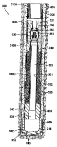
Figure 6 shows an apparatus 300. of the present invention for use in drilling
with
casing to form a substantially monobore well, or at least a cased wellbore
that does not
22
CA 02683763 2009-11-03
decrease in diameter with increased depth. A first casing string 310 has a
cutting
structure 315 attached to its lower end for drilling through a-formation 320
to form a
wellbore 305. The cutting structure 315 includes any earth removal member. The
cutting structure 315 is preferably a drill bit constructed of a drillable
material 312 such
as aluminum. The cutting structure 315 preferably includes small,
substantially
M1
spherical cutting members 313, preferably cbnstructed of tungsten carbide or
polycrystalline diamond, disposed around the drillable material 312 for use in
dritling
into the formation 320. The cutting structure 315 has at least one perforation
(noZzle)
316 extending therethrough to allow drilling fluid to circulate within the
formation 320.
The first casing string 310 includes casing sections 310A, 310B, and 310C
connected,
preferably threadedly connected, to one another. Any number of casing sections
may
be. threadedly connected to one another to form the first casing string 310,
or the first
casing string 310 may only include one casing section.
A lower portion of an inner diameter of the first casing string 310 has a cut-
away
portion 325 therein. The cut-away portion 325 of the first casing string 310
'has a larger
inner diameter than the remaining portion of the first casing string 310
disposed above
the cut-away portion 325, so that the cut-away portion 325 is an undercut
portion of the
- first casing string 310. The cut-away portion 325 provides a mating surface
for an
upper portion of a second casing string 81.0 (shown in Figure 7) when the
upper portion
of the second casing string 810 is expanded into the first casing string 310.
The mating
surface of the cut-away portion 325 is preferably non-expanding.
Disposed within the inner diameter of the first casing string 310 is a
drillable
cementing assembly 330 which facilitates the function of cementing an annular
space
335 between the outer diameter of. the first casing string 310 and the inner
diameter of
the wellbore 305. The cementing assembly 330, preferably a cement shoe
assembly,
comprises a longitudinal bore 323 running therethrough, providing a fluid flow
path for
cement and well fluids. A one-way valve, for example a check valve 350, is
located
within the longitudinal bore 323. The check valve 350 permits fluid entrance
from the .. :,-_.
well surface through the check valve 350 and into the longitudinal bore 323,
yet
prevents fluid from passing from the wellbore 305 into a portion of the first
casing string
310 above the check valve 350. A spring 351, as shown in Figure 6, may be used
to
bias the check valve 350 in a closed position. Any other mechanism which
permits
23
CA 02683763 2009-11-03
one-way fluid flow through the longitudinal bore 323 may be utilized with the
present
invention.
An annular area 321 adjacent to the check valve 350 and between the inner
diameter of the first casing string 310 and the longitudinal bore 323 is
filled with a
drillable material, preferably cement, to stabilize the longitudinal bore 323.
One or
more upsets 352 (preferably a plurality of upsets 352) are disposed in the
first casing
string 310 to hold the cement in place and prevent axial movement thereof.
Lining the
longitudinal bore 323 between the check valve 350 and a lower end of the first
casing
string 310 is a tubular member 331. An annular area 332 between the tubular
member
331 and the first casing string 310 is filled with an aggregate material such
as sand.
The purpose of the aggregate material is to support the tubular member 331.
Below the annular area 332 filled with aggregate material is a drillable
portion
340. The drillable portion 340 is connected, preferably threadedly connected,
to a
lower end of the first casing string 310 so that a longitudinal bore 333
running through
the drillable portion 340 is in line with the longitudinal bore 323. The
drillable portion
340 is constructed of drillable material to support the aggregate material in
the annular
space 332 and has wear-resistant characteristics so that the material is not
affected by
hydraulic pressure characteristic of the wellbore 305 conditions. Preferably,
the
drillable portion 340 is formed of a solid material, and even more preferably,
with a
composite material such as fiberglass.
One or more grooves (not shown) may be disposed on an outer portion of the
drillable material 340 around the perimeter of the drillable material 340
where the
drillable material 340 meets the first casing string 310. The groove ensures
that the
drillable portion 340 falls away from the first casing string 310 as the
second casing
string 810 drills through the first casing string 310, as described below.
Disposed in an
upper portion of the drillable material 340 are one or more radially extending
voids (not
shown) formed in the composite material which extend from the first casing
string 310
inward to terminate adjacent to the tubular member 331. The voids in the
composite
material ensure that the outermost portions of the drillable material 340 fall
away from
the first casing string 310 as the second casing string 810 drills through the
first casing
string 310.
24
CA 02683763 2009-11-03
Figure 7 depicts the second casing string 810 drilling through the first
casing string
310. The second casing string 810 has an expandable earth removal member,
preferably an
expandable cutting structure 805, operatively connected to its lower end. The
expandable
cutting structure 805 is extendable and retractable between a closed,
retracted position
shown in Figure 7 and an open, expanded position, as shown in Figure 8 (also
described
above in relation to Figures 1-5). The expandable cutting structure 805 is in
the closed
position while drilling through the cementing assembly 330 within the first
casing string 310
because the expandable cutting structure 805 is too large in diameter to
travel through the
first casing string 310 while in the open position. The expandable cutting
structure 805 is
manipulated into the open position to drill into the formation 320 to a second
depth at which
to set the second casing string 810 at the end of the operation, as shown in
Figures 8-10. In
the closed position, the expandable cutting structure 805 is smaller in
diameter than in the
open position.
An example of an expandable cutting structure 805 in the form of an expandable
drill
bit is disclosed in U.S. Patent Number 6,953,096 filed on December 31, 2002.
The
expandable cutting structure 805 generally includes a set of blades 806, 807
which move
between the open and closed position. Hydraulic fluid flowing through the
expandable
cutting structure 805 controls the movement of the blades 806, 807 between the
open and
closed position.
The expandable cutting structure 805 is preferably an expandable drill bit. A
plurality
of cutting members 808 is disposed on an outer portion of the blades 806, 807.
The cutting
members 808 are typically small and substantially spherical and may be made of
tungsten
carbide or polycrystalline diamond surfaces. The blades 806, 807 are
constructed and
arranged to permit the cutting members 808 to contact and drill into the earth
when the
blades 806, 807 are expanded outward and not ream the wellbore 305 or
surrounding
casing string 310 when the blades 806, 807 are collapsed inward.
Generally, one or more nozzles 385 of the expandable cutting structure 805 are
in
fluid communication with a longitudinal bore through the second casing string
810. The
nozzles 385 allow jetting of the drilling fluid during the drilling operation
through the
CA 02683763 2009-11-03
first casing string 310 to remove any cutting build-up which may gather in
front of the blades
806, 807. The nozzles 385 also permit jetting of the drilling fluid during the
drilling operation
through the formation 320 below the first casing string 310 to form a path for
the second
casing string 810 through the formation 320. Furthermore, the nozzles 385 are
used to
create a hydraulic pressure differential within the bore through the second
casing string 810
to cause the blades 806, 807 of the expandable cutting structure 805 to expand
outward, as
described in U.S. Patent Number 6,953,096.
Figure 9 illustrates the second casing string 810 being expanded into the
first casing
string 310 by an expander tool 400. Any expander tool may be used with the
present
invention which is capable of expanding the second casing string 810 by
elastic or plastic
deformation radially outward, preferably into contact with the first casing
string 310,
including a mechanical expander such as an expander cone. The expander tool
400
depicted in Figure 9 is used to expand the second casing string 810 from the
lower end of
the second casing string 810 upward with pressurized fluid supplied through a
working string
406. In the alternative, the expander tool 400 may be used to expand the
second casing
string 810 from the top down. The expander tool 400 includes a body 402 which
is hollow
and generally tubular with a connector 404 for connection to the working
string 406. The
body 402 includes one or more recesses 414 to hold a respective roller 416.
Each of the
mutually identical rollers 416 is near-cylindrical and slightly barreled. Each
of the rollers 416
is mounted by means of a bearing (not shown) at each end of the respective
roller for
rotation about a respective rotation axis which is parallel to the
longitudinal axis of the
expander tool 400 and radially offset therefrom. The inner end of a piston
(not shown) is
exposed to the pressure of fluid within the hollow core of the expander tool
400, and the
pistons serve to actuate or urge the rollers 416 against the inner diameter of
the second
casing string 810 therearound.
In Figure 9, the expander tool 400 is shown in an actuated position and is
expanding
the diameter of the second casing string 810 radially outward, preferably into
the inner
diameter of the wellbore 305 and into the cut-away portion 325 of the first
casing string 310.
Typically, the expander tool 400 rotates as the rollers 416 are actuated and
the expander
tool 400 is urged upwards in the wellbore 305. In this manner, the expander
tool 400 can be
used to enlarge the diameter of the second
26
CA 02683763 2009-11-03
casing string 810 circumferentially to a uniform size along a predetermined
length in the
wellbore 305.
Figure 11 depicts an alternate embodiment of an apparatus 600 of the present
invention. A first casing string 610 has an earth removal member, preferably a
cutting
structure 615, operatively attached to its lower end. The cutting structure
615 is
preferably a drill bit constructed of a drillable material 612, preferably
aluminum, and
small, substantially spherical cutting members 613, preferably constructed of
tungsten
carbide or polycrystalline diamond, disposed around the drillable material 612
for
drilling into a formation 620. The cutting structure 615 includes any earth
removal
member. The cutting structure 615 has at least one perforation (nozzle) 616
extending
therethrough to allow drilling fluid to circulate within the fonnation 620
while drilling.
An attenuator 505 is disposed on or in the frst casing string 610. In the
embodiment shown, the attenuator 505 is disposed circumferentially around an
outer
diameter of a lower end of the first casing string 610. The attenuator 505 is
preferably
compressible due to radial force, but capable of withstanding hydrostatic
pressure
within a wellbore 605. Cement or another comparable physically alterable
bonding
__ material must be.capable of bonding to the attenuator 505. Preferably, the
attenuator
505 is constructed of compressible aluminum.
The attenuator 505 includes a wall 510 located a distance radially from the
outer
diameter of the first casing string 610. The wall 510 is connected to the
first casing
string 610 by one or more webs 515, preferably a plurality of webs 515,
extending
radially therefrom. In between the plurality of webs 515 is at least one void
area 520.
The wall 510 and the plurality of webs 515 prevent cement and other fluids
from
entering the void areas 520, so that the webs 515 compress into the void areas
520
upon radial force exerted by an expander tool 400 (see Figure 14A).
- In an alternate embodiment, the attenuator 505 may be constructed of a
compressible material with voids disposed therein. In this embodiment, because
the
= material is inherently compressible, the webs 515 and the void areas 520 are
not
necessary. Preferably in this embodiment, the attenuator 505 is constructed of
a
porous material which is compressible due to radial force, but withstands
hydrostatic
pressure. More preferably, the attenuator 505 is constructed of styrofoam.
27
CA 02683763 2009-11-03
F'igures 12-13 depict a second casing string 71.0 with an expandable earth
removal member, preferably an expandable cutting structure 705, operatively
connected to its lower end. The expandable cutting structure 705 and the
second
casing string 710 are substantially identical in structure and operation to
those
described above in relation to Figures 6-10. Figure 14 shows the expander tool
400,
which is substantially identical in structure and operation to the expander
tool 400 of
Figure 9, expanding the second casing string 710 into contact with the first
casing string
610. The attenuator 505 is shown compressed by the expander tool 400 in
Figures 14
and 14A.
In the operation of the first embodiment illustrated in Figures 6-10, the
first
casing string 310 with the cutting structure 315 attached thereto is lowered
into the
formation 320 with a draw works (not shown), for example, and at least a
portion of the
first casing string 310 (e.g., the cutting structure 315) may optionally be
simultaneously
rotated, preferably by a top drive (not shown) or a mud motor (not shown).
While the
first casing string 310 is being drilled into the formation 320, driAing fluid
is
simultaneously introduced into the inner diameter of the first casing string
310.
Referring to Figure 6, the fluid flows through the first casing string 310,
through the
check valve 350, through the longitudinal bore 323, through the perforations
316 in the
cutting structure 315, and up through the annular space 335. The check valve
350
prevents the fluid from flowing back up through the first casing string 310 to
the surFace,
thus forcing the fluid out into the formation 1320.
After the first casing string 310 is drilled to the desired depth within the
formation
320, the flow of drilling fluid is halted. To determine when the first casing
string 310 has
reached the desired depth within the formation 320, logging-while-drilling or
measuring-
while-drilling may be utilized, as is known by those skilled in the art.
Specifically, one or
more logging and/or measuring tools may be employed within or on the 'firsfi
casing
string 310 to determine by measuring one or more geophysical parameters in the
formation 320 whether the first casing string 310 is proximate to the desired
location.
Exemplary geophysical parameters which may be sensed within the formation 320
include but are not limited to resistivity of the formation 320, pressure, and
temperature.
28
CA 02683763 2009-11-03
A physically alterable bonding material, preferably a setting fluid such as
cement, may then be introduced into the first casing string 310. A volume of
cement is
introduced into the first casing string 310 which is sufficient to fill at
least a portion of
the annular space 335 between the first casing string 310 and the wellbore
305, thus
cementing the first casing string 310 into the formation. 320. The cement
flows through
the first casing string 310, through the check valve 350, through the
longitudinal bore
323, through the perforations 316 in the cutting structure 315, and up through
the
annular space 335. The check valve 350 prevents the cement from flowing back
up:
through the casing string 310 to the surface, thus forcing the cement flow out
into the
formation 320. After the cement is pumped into the wellbore 305, drilling
fluid may
optionally be pumped into the first casing string 310 to ensure that most of
the cement
exits the lower end of the cutting structure 315. Figure 6 shows the first
casing string
310 set at the desired depth. within the formation 320 by cement within the
annular
space 335.
Once the first casing string 310 has been set within the formation 320 _when
the
cement cures, the second casing string 810 is utilized to drill through the
drillable
cementing assembly 330 within the first casing string 310. The outer diameter
of the
second casing string 810 is necessarily smaller than the inner diameter of the
first
casing string 310, so that the second casing string 810 fits within the first
casing string
310. Similarly, the largest portion of the expandable cutting structure 805
must be
smaller than the inner diameter of the first casing string 310 while the
expandable
cutting structure 805 is in the retracted position.
The second casing string 810 is lowered (e.g., by the draw works) into the
inner
diameter of the first casing string 310 while optionally a portion of the
first casing string
315 is being rotated by the top drive or mud motor. At the same time, drilling
fluid is
introduced into the inner diameter of the second casing string 810. The
drilling fluid
forces the drillable portions within the inner diameter of the first casing
string 310
upward toward the surface and forms a path through the first casing string 310
for the
~.
expandable cutting structure 805 to travel.
Figure 7 shows the second casing string 810 drilling through the inner
diameter
of the first casing string 310. Specifically, the second casing string 810
drills through
29
CA 02683763 2009-11-03
and substantially destroys the drillable cementing assembly 330, including the
check valve
350, the cement within the annular area 332, the tubular member 331, and the
drillable
portion 340. When the expandable cutting structure 805 drills to the cut-away
portion 325,
the inner diameter of the cut-away portion 325 may be too large for the
expandable cutting
structure 805 to reach while in the closed position; therefore, the voids in
the drillable
material 340 ensure that the portion of the drillable material 340 between the
inner diameter
of the first casing string 310 and the outermost portion of the expandable
cutting structure
805 falls out. In the alternative, the expandable cutting structure 805 may be
expanded to
the open position to drill through the drillable material 340 within the cut-
away portion 325.
Finally, the expandable cutting structure 805 drills through the cutting
structure 315. The
drillable material 312 on the cutting structure 315 is destroyed, while the
cutting members
313 are washed up toward the surface around the outer diameter of the second
casing
string 810 by the drilling fluid circulated through the wellbore 305.
After the expandable cutting structure 805 has destroyed the cutting structure
315,
the expandable cutting structure 805 is actuated so that the blades 806,807
are in the
extended position. The blades 806,807 are extended when the nozzles 385 cause
a
hydraulic pressure differential within the second casing string 810. In the
extended position,
the blades 806, 807 are capable of forming a portion of the wellbore 305 below
the first
casing string 310 with a larger inner diameter than the inner diameter of the
first casing
string 310 so that the second casing string 810 may be expanded to have the
same inner
diameter as the first casing string 310, thus forming a substantially monobore
well.
The second casing string 810 is then lowered and optionally at least a portion
of the
second casing string 810 is rotated while circulating drilling fluid so that
the second casing
string 810 is drilled to a second depth within the formation 320. The inner
diameter of the
wellbore 305 below the first casing string 310 is larger than the inner
diameter of the casing
string 310. Figure 8 shows the extended expandable cutting structure 805
drilling within the
formation 320 to a second depth.
CA 02683763 2009-11-03
Next, the expander tool 400 is lowered into the inner diameter of the first
casing
string 310 and the second casing string 810. Fluid is introduced through the
working
string 406 so that the pistons urge the rollers 416 against the inner diameter
of the
second casing string 810. The expander tool 400 rotates as the rollers are
actuated
and the expander tool 400 is urged upwards in the wellbore 305, so that the
second
casing string 810 is expanded along its length. A portion of the second casing
string
810 is expanded into contact with the cut-away portion 325. As shown in Figure
9, the
upper portion of the second casing string 810 is expanded into contact with
the cut-
away portion 325. In another aspect, a portion of the second casing string 810
is
expanded into contact with the cut-away portion 325, and the portion of the
second
casing string 810 located above the cut-away portion 325 and extending into
the inner
diameter of the first casing string 310 is cut off of the second casing string
810_
The expander tool 400 may be removed from the wellbore 305 after expansion
of the second casing string 810 is completed. Figure 10 shows a portion of the
second
casing string 810 expanded into contact with the cut-away portion 325 of the
first casing
string 310 and a remaining portion of the second casing string 81=0 expanded
into the
wellbore 305. The inner diameter of the portion of the second casing string
810 below
the first casing string 310 is at least at large as the 'inner diameter of'the
first casing
string 310, so that the inner diameter of the cased wellbore does not decrease
with
increased depth within the wellbore 305. Figure 10 shows essentially a
monobore well,
which denotes a wellbore which has substantially the same diameter at every
depth
and length: Additional casing strings may be used to drill through the second
casing
string 810. The additionai casing strings and the second casing string 810 may
inciude
cut-away .portions 325 with drillable portions 340 located therein and may be
expanded
into the previous casing strings.
After removal of the expander tool 400 from the wellbore 305, a cementing
operation may optionally be conducted to cement the second casing string 810
within
the formation 320. A physically alterable bonding material such as cement is
= introduced into the inner diameter of the first casing string 310, then
flows through the
inner diameter of the second casing string 810, through the nozzles 385, and
up
through the annular space 335. Additionai casing strings with expandable
cutting
31
CA 02683763 2009-11-03
structures operatively attached thereto may be used to drill through the
expandable
cutting structure 805 and the additional expandable cutting structures.
In the operation of the second embodiment shown in Figures 11-14A, the first-
casing string 610 with the cutting structure 615 operatively attached thereto
is lowered
and optionally at least a portion of the first casing string 610 is rotated as
described
above in relation to the casing string 310 of Figures 6-10. While the casing
string 610
is being drilled into the formation 620, drilling fluid is simultaneously
introduced into the
inner diameter of the casing string 610 so that the fluid flows through the
casing string
610, through the perforations 616 in the cutting structure 615, and up through
the
annular space 635 between the first casing string 610 and the formation 620.
The first casing string 610 is dril{ed to the desired depth within the
formafiion 620.
To determine when the first casing string 610 has reached the desired depth
within the
formation 620, logging-while-drilling and/or measuring-while-drilling may be
utilized, as
is known by those skilled in the art. Specifically, one or more -logging tools
and/or
measuring tools may be employed to determine by measuring one or more
geophysical
parameters in the formation 620 whether the first casing string 610 is
proximate to the
desired location. Exemplary geophysical parameters which may be sensed within
the
formation 620 include but are not limited to resistivity of the formation 620,
pressure,
and temperature.
After the first casing string 610 is drilled to the desired depth within the
formation
620, the flow of drilling fluid is halted. A physically alterable bonding
material,
preferably a setting fluid such as cement, may then optionally be introduced
into the
first casing string 610 to fill at least a portion of the annular space 635 as
described
above in relation to the first casing string 310 of Figures 6-10. The cement
flows
through the first casing string 610, through the perforations 616 in the
cutting structure
615, and up through the annular space 635 past the attenuator 505. After the
cement
is pumped into the wetlbore 605, drilling fluid may optionally be pumped into
the first
casing string 610 to ensure that most of the cement exits the lower end of the
cutting
structure 615. Figure 11 shows the first casing string 310 set at the desired
depth
within the formation 620 by cement within the annular space 635. Cement bonds
with
the wall 510 of the attenuator 505.
32
CA 02683763 2009-11-03
Next, the second casing string 710 is lowered and optionally at least a
portion of
the second casing string 710 is rotated into the first casing string 610 as
described in
relation to casing strings 310 and 810 of Figures 6-10. Drilling fluid is
simultaneously
circulated through the second casing string 710, out the nozzles 685, and up
through
the annular space between the first casing string 610 and the second casing
string 7:10.:
Initially, the expandable cutting structure 705 is in the retracted position
as it travels
through the inner diameter of the first casing string 610. Figure 12 shows the
second
casing string 710 running into the first casing string 610 with the expandable
cutting
structure 705 in the retracted position.
The expandable cutting structure 705 is then used to drill through the
drillable
material 612 of the cutting structure 615. The fluid circulating within the
wellbore 605
carries the cutting members 613 through the annular space between the inner
diameter
of the first casing string 610 and the outer diameter of the second casing
string 710
toward the surface. The expandable cutting structure 705 is then extended to
the open
position below the first casing string 605 as described above in relation to
the
expandable cutting structure 805 of Figures 6-10. Figure 13 shows the
expandable
cutting structure 705 forming a portion of the wellbore 605 below the first
casing string
- - 610 which is at least as large in inner diameter as the inner diameter of
the first casing
string 610.
The second casing string 705 is drilled to a second desired depth within the
formation 620. The expander tool 400 is then lowered into the wellbore 605 and
is
actuated to expand the second casing string 710 along its length as described
above in
relation to Figures 6-10. When the expander tool 400 is moved upwards (and/or
downwards) within the second casing string 710 to expand the portion of the
second
casing string 710 adjacent to the attenuator 505, the first casing string 610
bends
outward radially toward the inner diameter of the wellbore 605. The first
casing string
610 is able to move within the cement portion of the annular space 635 because
the
attenuator 505 is crushed by the expansion force exerted by the expander tool
400.
= Figure 14 illustrates the expander tool 400 expanding the second casing
string 710 to
compress the attenuator 505 so that the inner diameter of the portion of the
second
casing string 710 adjacent the attenuator 505 is at least as large as the
smallest portion
of the inner diameter of the first casing string 610.
33
CA 02683763 2009-11-03
Figure 14A shows the attenuator 505 after expansion_ The webs 515 are
compressed to invade the void areas 520, thus allowing room for the first
casing string
610 to move toward the inner diameter of the wellbore 605 to make room for the
second casing string 710. The wall 510 remains pressed against the cement
within the
annular space 635.
At the end of the operation, the expander tool 400 may be removed from the
wellbore 605. A physically alterable bonding material such as cement may
optionally
be introduced into the wellbore 605 and flowed through the casing strings 610,
710,
through the nozzles 685, and up through the annular space 635 to cement the
second
casing string 710 within the welibore.
In an additional aspect of the present invention, the second casing string 710
may also include an attenuator 505 at a lower portion around its outer
diameter.
Additional casing strings with expandable cutting structures attached thereto
and
attenuators around their outer diameters may then be used to drill through
previous
expandable cutting structures and experience expansion to compress the
attenuators,
as described above, to form a wellbore of a desired depth.
In a further additional aspect of the present invention, a portion of the
second
casing string 710 is expanded into contact with the first casing string 610,
and the
porfiion of the second casing string 710 located above the attenuator 505 and
extending
into the inner diameter of the first casing string 610 is cut off of the
second casing string
710.
In yet a. further additional aspect of the present invention, the attenuator
505 or
compressible member of Figures 11-14 may be located within an enlarged inner
diameter portion (not shown) of the first casing string 610. The second casing
string
710 may be used to drill through the first casing string 610_ as described
above - in
relation to Figures 11-14. Then, a portion of the second casing string 710 may
be
expanded into the enlarged inner diameter portion. The attenuator 505
compresses so
that the portion of the second casing string 710 is moveable through the
enlarged inner
diameter portion of the first casing string 610 to form a substantially
monobore well.
Additional casing strings may be used to drill through the second casing
string 710 and
subsequent casing strings and through the formation. The additional casing
strings as
34
CA 02683763 2009-11-03
well as the second casing string 710 may include enlarged inner diameter
portions and
attenuators disposed therein.
The cutting structures 315 and 615 and the expandable cutting structures 805
and 705 are described above as connected to the lower end of the casing
strings 310,
810, 610, and 710. It is understood that the cutting structures 315, 615, 805,
and 705
are operatively disposed at the lower end of the casing strings 310, 810, 610,
and 710,
so that the cutting structures may be disposed at any location on the casing
strings
where the cutting structures are capable of drilling through the formation. As
such, it is
understood that the cutting structure may be connected at, for example, a
middle
portion of the casing string, and the cutting structure may protrude below the
casing
string in a position to drill through the formation.
Providing a method and apparatus for drilling with casing to form a
substantially
monobore well by use of the embodiments of the present invention increases the
possible inner diameter of a cased wellbore formed by drilling with casing. As
a
consequence, flexibility in the tools which are capable of being run into the
cased
wellbore is increased. Furthermore, forming a substantially monobore well
using
drilling with casing technology in embodiments of the present invention allows
a
wellbore of substantially the same inner diameter along its length to be
formed in less
time compared to conventional drilling methods.
Embodiments of the present invention also advantageously provide apparatus
and methods for maintaining a fluid bypass around casing during a drilling
with casing
operation after hanging casing within an open hole or cased wellbore. Use of
embodiments of the present invention allows for creation of a substantially
monobore
well by drilling with.casing.
Figure 15 shows casing 910, at least a portion of the casing 910 profiled,
having
an earth removal member 950 operatively attached to its lower end. The casing
910
may include a casing section, or may include two or more casing sections
connected,
preferably threadedly connected to one another, to form a casing string 910.
The
casing 910 may be a tubular string, wherein only a portion of the tubular
string is
casing, or it may be only casing.
CA 02683763 2009-11-03
The earth removal member 950 is preferably a cutting structure, most
preferably
a drill bit, having one or more fluid passages 952 and/or 953 to allow for
fluid flow
therethrough. The earth removal member 950 may be an expandable cutting
structure,
the operation and structure of which is shown and described below in relation
to the
earth removal member 1550 of Figures 21-25. Alternately, the earth removal
member
950 may be drillable.
The earth removal member 950 may be attached to any portion of the casing
910 which allows for drilling with the casing 910 into a formation 905.
Preferably, the
connection between the earth removal member 950 and the casing 910 is
temporary to
allow for retrieval of the earth removal member 950 during the drilling:
operation
(described below). Figure 15 depicts the earth removal member 950 attached to
the
casing 910 at its lower end by a temporary, shearable connection 951.
The profiled casing 910 is shown in Figure 15B. The profiled casing 910 has a
generally tubular-shaped body with one or more gripping members 920 formed on
its
outer diameter at a first location, or a leg 935. Preferably, three legs 935
are formed on
the casing 910 at three locations, each leg 935 preferably having gripping
members
920 formed on its outer diameter. The gripping members 920, which are
preferably
slips having grit or teeth, provide gripping force to allow the casing 910 to
frictionally
engage a wetlbore 930 to hang the casing 910 within the wellbore 930.
One or more fluid bypass areas 940 are formed between the legs 935 to provide
a-fluid -path around the outside of the casing 910. The casing 910 is
preformed into an
irregular, profiled shape to create the bypass areas 940. The fluid bypass
areas 940,
as well as the casing 910, may be of any shape which allows for sufficient
circulation of
fluid around the outside of the casing 910 after the casing has been hung
within the
wellbore 930 and also permits eventual expansion of the casing 910
circumferentially
during the various stages of the drilling operation. Alternatively, the fluid
bypass areas
940 may be formed downhole from casing which is substantially circumferential.
A
sealing member 960 may be disposed around the outer diameter of the casing 910
to
seal between the casing 910 and the wellbore 930 upon expansion of the casing
910.
The sealing member 960 is preferably an elastomeric ring.
36
CA 02683763 2009-11-03
Referring again to Figure 15, a setting tool 1200, an expander tool 1100, and
one or more carrying dogs 931 are located on a running string 1300. The
running
string 1300 is releasably connected, preferably threadedly connected, to the
earth
removal member 950. The running string 1300 may also be releasably connected
to
the casing 910 by carrying dogs 931 disposed in slots 932 within the inner
surface of
the casing 910.
An exploded view of the setting tool 1200 is shown in Figure 15C. The setting.
tool 1200 has a body 1202 which is hollow and generally tubular and may have
connectors 1204 and 1206 for connection to other components of a downhole
assembly, including the earth removal member 950. The central body part has
one or
more recesses 1214 to hold one or more radially extendable setting members
1216.
Each of the recesses 1214 has parallel sides and extends from a radially
perforated
inner tubular core (not shown) to the exterior of the todl 1200. Each mutually
identical
setting member 1216 is generally rectangular having a beveled setting surface
and a
piston surface 1218 on the back thereof in fluid communication with
pressurized fluid
delivered by the running string 1300. Pressurized fluid provided from the
surface of the
well, via the running string 1300, can actuate the setting members 1216 and
cause
them to extend outward and to contact the inner wall of casing 910 to be-
expanded.
An exploded view of the expander tool 1100 is shown in Figure 15D. The
expander tool 1100, which is run into the wellbore on the running string
'1300, has
expandable, fluid actuated members disposed on a body. During expansion of
casing,
the casing walls are expanded past their elastic limit.
The expander tool 1100 has a body 1102 which is hollow and generally tubular
and may have connectors 1104 and 1106 for connection to other components (not
shown) of the downhole assembly. The connectors 1104 and 1106 may be of a
reduced diameter compared to the outside diameter of the longitudinally
central body
part of the expander tool 1100. The central body part has one or more
recesses,
shown here as three recesses 1114, to hold a respective expansion member,
prefcirably a roller 1116. Each of the recesses 1114 has parallel sides and
exdends
radially from a radially perforated tubular core (not shown) of the expander
tool 1100.
Each of the mutually identical rollers 1116 is generally cylindrical and
barreled.
37
CA 02683763 2009-11-03
Each of the rollers 1116 is mounted by means of an axle 1118 at each end of
the
respective roller 1116 and the axles 1118 are mounted in slidable pistons
1120. The
rollers 1116 are arranged for rotation about a respective rotational axis
which is parallel
to the longitudinal axis of the expander tool 1100 and, in the embodiment
shown,
radially offset therefrom at approximately 120-degree mutual circumferential
separations around the central body 1102. The axles 1118 are formed as
integral end
members of the rollers 1116 and the pistons 1120 are radially slidable, one
piston 1120
being slidably sealed within each radially extended recess 1114. The inner end
of each
piston 1120 is exposed to the pressure of fluid within the hollow core of the
expander
tool 1100 by way of the radial perforations in the tubular core. In this
manner,
pressurized fluid provided from the surface of the well, via the running
string 1300, can
actuate the pistons 1120 and cause them to extend outward and to contact the
inner
wall of the casing 910 to be expanded.
Additionally, at an upper and a lower end of the expansion tool 1100 are
preferably a plurality of non-compliant rollers 1103 constructed and arranged
to initially
contact and expand the casing 910 prior to contact between the casing 910 and
fluid
actuated rollers 1116. Unlike the compliant, fluid actuated rollers 1116, the
non-
compliant rollers 1103 are supported only with bearings and do not change
their radial-
~
position with respect to the body 1102 of the expander tool 1100.
As shown in Figure 16, the expansion tool 1100 has a bore 9180 therethrough
through which fluid may flow at various stages of the operation. Similarly,
the setting
tool 1200 has a bore 1280 therethrough through which fluid may flow at various
stages
of the operation. The bore 1180 of the expansion tool 1100 preferably has a
larger
diameter than the bore 1280 of the setting tool 1200. A bore 980 also exists
below
bore 1280 which preferably has an even smaller diameter than the diameter of
bore
1280. The operation and purpose of the increasingly smaller bore 980, 1180,
1280
sizes are described below.
When using the expansion tool 1100, the casing being acted upon by the
expansion tool 1100 is expanded past its point of elastic deformation. In fhis
manner,
the inner diameter and outer diameters of the expandable tubular are increased
in the
wellbore. By rotating the expansion tool 1100 in the wellbore and/or moving
the
38
CA 02683763 2009-11-03
expansion tool 1100 axially in the weilbore with the rollers 1116 actuated,
the casing
910 can be expanded by plastic deformation into the wellbore 930 (or already
existing
. casing of a cased wellbore).
In operation, the running string 1300 is initially made up to include the
carrying
dogs 931, expander tool 1100, and setting tool 1200 therein. The lower end of
the
running string 1300 is threadedly connected to the earth removal member 950
above its
fluid passages 952 and 953. The running string 1300 components are configured
so.
that the setting tool 1200 is located within the profiled portion of the
casing 910 at the
lower end, of the casing 910. The carrying dogs 931 are extended into
corresponding
slots 932 in the casing 910. In this configuration, the casing 910 with the
releasably
connected running string 1300 is run into the formation 905. The earth removal
member 950 may be rotated by a mud motor (not shown) while the casing 910 is
being
run into the formation 905. In the alternative, the entire casing string 910
including the
earth removal member 950 may be rotated while running the casing 910 into the
formation 905. It is also contemplated that, if the formation 905 is
sufficiently soft, the
casing 910 may be merely pushed into the formation 905 while circulating
drilling fluid
("jetted") into the formation 905 without rotating the earth removal member
950 or the
- casing 910. Any combination of rotating the earth removal member -950 only,
rotating
the casing 910, or jetting the casing 910 may also be utilized to drill the
casing 910 into
the formation 905 to form the wellbore 930.
While the casing string 910 is drilling into the formation 905, drilling fluid
F is
preferably introduced into the inner diameter of the running string 1300. The
drilling
fluid F then travels through the expander tool 1100 and setting tool 1200,
through the
passages 952 and 953 through the earth removal member 950 and out through the
earth removal member 950, then up to the surface of the well through an
annulus A
between the outer diameter of the casing 910 and the inner diameter of the
welibore
930 which is being drilled. The casing string 910 is drilled to the desired
depth within
the formation 905, as shown in Figure 15. Figure 15A illustrates a downward
view
along line 15A 15A of Figure 15 at this step in the o.peration. The setting
members
1216 are unextended, and the casing 910 is in position for expansion by
extension of
the setting members 1216.
39
CA 02683763 2009-11-03
Next, a ball 1291 is dropped into the bore 1180, as shown in Figure 16. The
ball
1291 is sized so that it stops at a ball seat 1290 formed at the junction
between the
larger bore 1280 and the smaller bore 980. After the ball 1291 is seated at
the ball seat
1290, fluid F is introduced into the bore 1180. The presence of the ball 1291
halts fluid
F flow through the bore 980 and increases fluid pressure within the setting
tool 1200.
The increased fluid pressure actuates the setting members 1216, thereby
forcing the
setting members 1216 outwards radially into contact with the legs 935 so that
the
profiled portion of the casing 910 including the legs 935 is expanded past its
elastic limit
along at least a portion of its outer diameter proximate to where the gripping
members
920 are formed. The outer diameter of the legs 935 of the casing 910
grippingly
engage the wellbore 930 to hang the casing 910 within the wellbore 930, while
at the
same time leaving a pathway through which fluid may bypass through the fluid
bypass
areas 940 in between the expanded legs 935. Figure 16 shows the casing 910 set
within the wellbore 930. Figure 16A shows line 16A-16A of Figure 16 with the
setting
members 1216 having expanded the legs 935 into contact with the wellbore 930
and
the fluid bypass areas 940 remaining intact. In an alternative embodiment, the
expander tool 1100 may be utilized to expand the legs 935 to frictionally
engage the
wellbore 930 by positioning the expander tool 1100 at approximately the
location of the
setting tool 1200 in Figures 15-20, thus eliminating the need for the setting
tool 1200.
After the casing 910 has been expanded at the legs 935 into frictional contact
with the wellbore 930, fluid pressure is increased within the bore 1280 to a
fluid
pressure above the rated limit of the ball seat 1290 to blow the ball 1291 out
of the ball
seat 1290. When the ball 1291 is blown out of the ball seat 1290, fluid flow
through the
bores 1180; 1280, and 980 within the running string 1300 is again unimpeded.
At this
point, the wellbore 930 may be conditioned and/or cemented by any conventional
means. A cementing operation may be conducted by introducing cement or some
other physically alterable bonding material into the running string 1300, as
shown in
Figure 17. Cement flows through the bores 1180, 1280, and 980, out through the
passages 952 and 953 in the earth removal member 950, then up through the
annulus
Abatween the outer diameter of the casing 910 and the wellbore 930 to the
desired
height. When flowing up through the annulus A, the cement flows up through the
fluid
bypass areas 940 and then up through the annulus A between the unexpanded
casing
CA 02683763 2009-11-03
910, which is above the profiled portion of the casing 910, and the wellbore
930. Figure
17 shows the cement having risen to a level at the top of the casing 910, but
it is
contemplated that cement may rise to any level with respect to the casing 910.
After sufficient cement has been introduced into the annulus A but before the
cement has cured; the carrying dogs 931 are retracted from the slots 932 and
the
temporary connection 951 connecting the earth removal member 950 to the casing
910
is released. The temporary connection 951 is preferably released by shearing
the earth
removal member 950 from the casing 910 by downward pushing or upward pulling
of
the running string 1300. Drilling fluid F is then introduced into the running
string 1300
and the mud motor rotates the earth removal member 950 to driil the running
string
1300 to a further depth within the formation 905. Other methods of drilling
mentioned
above, including rotating the entire running string 1300 or jetting the
running string 1300
into the formation 905 may also be utilized, alone or ir1 combination with one
another.
The running string 1300 is drilled to a further depth within the formation 905
to allow
location of the expander toot 1100 adjacent the profiled lower end of the
casing 910
within the casing 910. Figure 18 shows the running string 1300 drilled to a
further
depth within the formation 905 to extend the welibore 930.
Next, the drilling of the running string 1300 is halted, and fluid flow
through the
running string 1300 may be stopped. The running string 1300 is preferably
drilled to
the depth where the expander tool 1100 is located at the lowermost end of the
casing
910. In this embodiment, the expansion of the casing 910 is from the bottom
up. In the
alternative, the expander tool 1100 may be located adjacent to the upper end
of the
profiled portion.of the casing 910, if the expander tool 1100 is moved
downward for the
expansion of the profiled portion of the casing 910.
As shown in Figure 19, a ball 1191, larger than the ball 1291, is introduced
into
the bore 1180 and stops in a ball seat 1190. (In an alternate embodiment, the
ball
} 1191 may be placed within the ball seat 1190 prior to locating the expander
tool 1100 at
the proper axial position adjacent the profiled portion of the casing 910.) .
Pressure
build=up from the increased fluid pressure instigated by the presence of the
ball 1191
within the expander tool 1100 activates the expander tool 1100 so that the
rollers 1116
are urged radially outward from the expander tool 1100 to contact the casing
910
41
CA 02683763 2009-11-03
therearound. The expander tool 1100 exerts force against the wall of the
casing 910
while rotating and preferably (but optionally) moving axially within the
casing 910. The
rollers 1116 thereby expand the casing 910 wall past its elastic limits around
the
circumference of the casing 910 at the profiled lower end.
Gravity and the weight of the components can move the expander tool 1100
downward in the casing 910 even as the rollers 1116 of the expander tool -
1100 are
actuated. Altematively, the expansion can take place in a"bottom up" fashion
b.y
providing an upward force on the running string 1300. A tractor (not shown)
may be
used in a lateral wellbore or in some other circumstance when gravity and the
weight of
the components are not adequate to cause the actuated expander tool 1100 to
move
downward along the wellbore 930. Additionally, the tractor may be necessary if
the
expander tool 1100 is to be used to expand the casing 910 wherein the tractor
provides
upward movement of the expander tool 1100 in the wellbore 930. Preferably, the
non-
compliant rollers 1103 at the lower end of the expander tool 1100 contact the
inner
diameter of.the casing 910 as the expansion tool 1100 is raised. This serves
to smooth
out the legs 935 and reform the casing 910 into a circular shape prior to
fully expanding
the casing 910 into the wellbore 930. The casing 910 is then expanded into
circumferential contact with the wellbore 930. Figure-19 shows the expander
tool 1100
in the process of expanding the lower, profiled portion of the casing 910 into
circumferential contact with the wellbore 930, from the bottom up.
The expander tool 1100 is preferably then utilized to expand the remainder of
the casing 910 above the profiled portion to a desired extent, preferably
leaving at least
some cement outside the -casing 910 to securely set the casing 910 within the
wellbore
930. The remaining portion of the casing 910 may be expanded from the bottom
up or
from the top down. Expanding this remaining portion increases the inner
diameter of
the casing 910 along its length, thus expanding the available diameter within
the
wellbore 930. After the expansion is complete, the cement may be allowed to
cure to
set the casing 910 within the wellbore 930.
Fluid pressure is then increased to a pressure above the operating pressure of
the expander tool 1100 to blow the ball 1191 through the frangible ball seat
1190. The
ball 1191 then flows through the running string 1300 and to the surface with
the fluid up
42
CA 02683763 2009-11-03
through the annulus between the inner diameter of the casing 910 and the outer
diameter of the running tool 1300. Consequently, a fluid path through the
bores 980,
1180, and 1280 is again unobstructed and the rollers 11.16 of the expander
tool 1100
are retracted. The retractable earth removal member 950 is retracted, and the
running
string 1300 is removed from the wellbore 930.
Figure 20 shows the casing 910 set within the wellbore 930 after the running
string 1300 is removed. The casing 910 is preferably bell-shaped at the end of
the
expansion process, so that the casing 910 has a larger inner diameter at its
lower end
to permit a subsequent casing section or casing string (not shown) to be
expanded into
the bell-shaped portion. Expanding the subsequent casing section or casing
string into
the bell-shaped lower end of the casing 910 allows for formation of a
substantially
monobore well, or a cased wellbore having an inner diameter that does not
decrease
with increasing depth. The process shown in Figurds 15-20 may be repeated any
number of times with any number of casing strings or casing sections expanded
into
one another to form a cased wellbore of any desired depth.
Figure 20A shows the bell-shaped portion of the casing 910 along line 20A-20A
of Figure 20. The lower portion of the casing 910 is expanded into contact
with the
wellbore 930 to form an essentially circumferential inner diameter of the
casing 910.
In an alternate erribodiment, the earth removal member 950 may be drillable
rather than retractable. While a ball and ball seat arrangement is described,
it should
be understood that any appropriate valve arrangement may be used, such as a
dart or
a sleeve for isolating fluid flow from the running string 1300 to the setting
tool 1200
and/or expander tool 1100.
Figures 21-25 illustrate an alternate embodiment of the present invention.
Figure 21 shows casing 1500 drilling a wellbore 1510 into a fomnation 1515.
The
-casing 1500 may include a casing section, or may include two or more casing
sections
connected to one another, preferably threadedly connected to one another, to
form a
= casing string. A portion of the casing 1500 has a fluid path therethrough.
The fluid
path in the embodiment of Figure 21 is in the form of one or more openings
1525 to
allow setting fluid, such as cement, to pass through the casing 1500.
43
CA 02683763 2009-11-03
An earth removal member 1550 is operatively connected to a lower end of the
casing
1500. As shown in Figure 21, the earth removal member 1550 is shearably
connected to the
lower end of the casing 1500. The earth removal member 1550 is preferably a
cutting
structure, more preferably a drill bit. The earth removal member 5 1550 is
preferably
expandable and retractable, and may be the retractable drill bit described in
U.S. Patent
Number 6,953,096, filed on December 31, 2002.
The expandable earth removal member 1550 generally includes a set of blades
which move between the open and closed position. Hydraulic fluid flowing
through the earth
removal member 1550 controls the movement of the blades between the open and
closed
position. The expandable earth removal member 1550 may be retrievable after
expansion in
its retracted state. In the alternative, the expandable cutting structure 1550
may be an
expandable drill bit constructed of drillable material such as aluminum, as
described in U.S.
Patent Number 6,953,096. The expandable drill bit of U.S. Patent Number
6,953,096 has a
plurality of cutting members disposed on an outer portion of the blades. The
cutting
members are typically small and substantially spherical, and may be made of
tungsten
carbide or polycrystalline diamond surfaces. The blades are constructed and
arranged to
permit the cutting members to contact and drill the earth when the blades are
expanded
outward and not ream the wellbore or surrounding casing when the blades are
collapsed
inward.
Fluid passages 1552 and 1553 extend through the earth removal member 1550 to
provide a fluid path through the earth removal member 1550. Fluid passages
1552 and 1553
are in fluid communication with a longitudinal bore through the casing and
allow jetting of the
drilling fluid during the drilling operation through the casing to remove any
cuttings build up
which may gather in front of the blades and to form a path for the casing
through the
formation. Furthermore, the fluid passages 1552 and 1553 (also termed nozzles)
are used
to create a hydraulic pressure differential within the bore through the casing
to cause the
blades of the expandable cutting structure to expand outward, as described in
U.S. Patent
Number 6,953,096.
44
CA 02683763 2009-11-03
The casing 1500 may optionally include one or more sealing members 1560 on
its outer diameter for sealing an annular area A between the casing 1500 and
the
wellbore 1510. Additionally, the casing 1500 may optionally include one or
more
gripping members 1520 on a portion of its outer diameter to allow the casing
1500 to be
initially hung within the wellbore 1510 due to frictional engagement of the
gripping
members 1520 with the wellbore 1510. The sealing members 1560 are preferably
constructed of an elastomeric material, and the gripping members 1520 are
preferably
slips. Preferably, the sealing members 1560 and gripping members 1520 are
located
below the openings 1525, and the sealing members 1560 are located above the
gripping members 1520 on the casing 1500.
A running string 1570 is releasably connected to the casing 1500, preferably
by
retractable carrying dogs 1531 disposed in slots 1532 in the inner diameter of
the
casing 1500. The expander tool 1100 shown and desctibed in relation to Figure
15D is
connected, preferably threadedly connected, to a lower end of the running
string 1570.
The lower end of the expander tool 1'100 may be threadedly connected to an
upper
portion of the earth removal member 1550.
In operation, as shown in Figure 21, the casing 1500 is. lowered into the
formation 1515 while introducing drilling fluid through the running string
1570. The
earth removal member 1550 (or the casing 1500 itself) may be rotated, if
necessary or
desired to drill through the formation 1515 to form the wellbore 1510, while
the casing
1500 is lowered into the formation 1515. While the casing 1500 is drilling
into the
formation 1515, the drilling fluid F flows through the running string 1570,
through the
passages 1552 and 1553, and up through the annular area A between the casing
1500
and the weilbore 1510. The casing 1500 may be drilled to a further depth than
the "
eventual setting. depth of the casing 1500 within the wellbore 1510 to allow
additional
room for the running string 1570 to be lowered within the drilled-out portion
of the
wellbore 1510 in further steps in the operation of the present invention.
Next, as illustrated in Figure 22, a ball 1591 is introduced into a bore 1580
of the
running string 1570. The.ball 1591 stops at a ball seat 1590 within the bore
1580 of the
running string 1570. Fluid F is then introduced into the running string 1570,
and the
pressurized fluid forces the rollers 1116 (see Figure 15D) of the expander
tool 1100 to
CA 02683763 2009-11-03
extend radially outward from the expander tool 1100 to contact the casing 1500
therearound. The rollers 1116 thereby expand the wall of the casing 1500 past
its
elastic limits in the portions at which each roller 111f extends to initially
anchor the
casing 1500 within the wellbore 1510.
The carrying dogs 1531 are next retracted from the slots 1532 in the casing
1500, and the earth removal member 1550 is removed from its releasable
engagement
with the casing 1500. The expander tool 1100 may now be rotated relative to
the
casing 1500 to expand the casing 1500 along its circumference into the
wellbore 1510,
as described above in relation to Figures 15-20. The lack of attachment
between the
casing 1500 and the running string 1570 allows the expander tool 1100 to move
axially
downward and rotate to expand the remainder of the lower portion of the casing
-1500,
as shown in Figure 23. The axial movement of the expander tool 1100 in
relation to the
casing 1500 is accomplished as described above in relation to Figures 15-20.
The expander tool 1100 exerts force against the wall of the casing 1500 while
rotating and moving axially within the casing 1500. The rollers 1116 thereby
expand
the casing 1500 wall past its elastic limit around the circumference of the
casing 1500
at the lower end. Alternatively, the expansion can take place in a "bottom up"
fashion
by providing an upward force on the running string 1570, as described above in
relation
to Figures 15-20.
Fluid pressure in the running string 1570 is then increased to a pressure
above
the operating pressure of the expander tool 1100. The ball 1591 is blown
through the
frangible ball seat 1590, then flows up to the surface with the fluid up
through the
annulus A. The rollers 1116 of the expander tool 1100 are thus retracted due
to lack of
fluid pressure within the expander tool 1100, and the bore 1580 is again
unobstructed
to allow fluid flow therethrough.
As shown in Figure 24, a setting fluid 1555, preferably cement, is next
introduced into the running string 1570 from the surface of the wellbore 1510.
The
setting fluid 1555 flows through the running string 1570, out through the
passages 1552
and 1-553 of the earth removal member 1550, up through the annulus between the
outer diameter of the running string 1570 and the inner diameter of the casing
1500,
then out through the openings 1525 into the annulus A between the casing 1500
and
46
CA 02683763 2009-11-03
the wellbore 1510. The setting fluid 1555 may fill only a portion of the
annulus A or, in
the alternative, may be allowed to fill up the annulus A. Figure 24 shows the
setting
fluid 1555 flowing up through the annulus A through openings 1525 to
substantially fill
the annulus A with setting fluid 1555.
. When sufficient setting fluid 1555 exists in the annulus A, setting fluid
1555 is no
longer introduced into the running string 1570.. After halting the: setting
fluid 1555 flow,
the running string 1570 is moved axially upward within the wellbore 1510 so
that the
rollers 1116 of the expander tool 1100, upon radial. extension, contact the
unexpanded
portion of the. casing 1500 which is above the portion of the casing 1500
already
expanded into the wellbore 1510. A second ball (not shown), which is larger
than the
ball 1591, may be introduced into the running string 1570. The second ball
stops in a
second ball seat (not shown), which is larger than the ball seat 1590. Again,
pressurized fluid is flowed into the bore 1580 of the rUnning string 1570 to
force the
rollers 1116 radially outward, and the expander tool 1100 is rotated and moved
upward
axially to expand the portion of the casing 1500 having the openings 1525
therein into
contact with the wellbore 1510. Expanding the openings 1525 into the wellbore
1510
prevents the openings 1525 from becoming a weak spot in the casing 1500 of the
cased wellbore, and closes off the ports into the anntllus A. -
To move the expander tool 1100 upward axially, the earth removal member
1550 may be retracted to allow it to fit within the inner diameter of the
casing 1500 by
methods such as those disclosed in U.S. Patent Application Serial Number
10/335,957,
which was above inc.orporated by reference.
. Before the setting ftuid 1555 cures, the upper portion of the casing 1500
above
the openings 1525_ is preferably expanded by the expander tool 1100 to some
extent to
increase the available space within the inner diameter of the casing 1500.
This upper
portion may be expanded from the bottom up, or from the top down. Preferably,
the
upper portion is not expanded into frictional contact with the wellbore so
that at least
some setting fluid 1555 remains within the annulus A to set the casing 1500
within the
welll5ore 1510.
47
CA 02683763 2009-11-03
The running string 1570 is then removed from the wellbore 1510. The setting
fluid 1555 may be allowed to cure to set the casing 1500 within the wellbore
1510.
Figure 25 shows the casing 1500 set within the welibore 1510.
An additional casing (not shown) may then be drilled into the wellbore 1510 in
the same manner as described in relation to casing 1500, and then the upper
portion of
the additional casing expanded into the lower portion of the casing 1500,
according to
the method described in Figures 21-25. Multiple casings (not shown) may also
be
drilled and set in the same manner. In this way, a substantially monobore
well, having
substantially the same inner diameter along the length of the wellbore 1510,
may be
formed with one run-in of each casing 1500.
In another embodiment, the earth removal member 1550 of the embodiment
shown in Figures 21-25 may, rather than being retractable, be drillable. For
example,
the earth removal member 1550 may be a dritlable bit. In this alternate
embodiment, a
second casing (not shown) may be used to drill through the earth removal
member
1550 when in the process of casing the wellbore 1510 with the second casing.
The expander tool 1100 described above in relation to the operations shown in
Figures 15-25 may be any rotary expansion tool, whether fluid operated or
mechanically operated. The expansion tool 1100 may in an altemate embodiment
be
an expander cone or any other mechanical apparatus capable of expanding
expandable tubing past its elastic limit.
In another aspect, the present inverition provides a method of drilling a
lateral
wellbore comprising forming the lateral wellbore from a parent wellbore in a
manner
whereby an inner diameter of the lateral wellbore is at least as large as an
inner
diameter of the parent wellbore. In one embodiment, the lateral wellbore is
formed in a
single trip into the well. In another embodiment, the lateral is formed with
an
expandable bit. In another embodiment still, the lateral wellbore is formed
with a bit
located at the end of a string of liner. In another embodiment still, the
parent welibore
is lined with casing. In another embodiment-still, the method includes placing
a liner in
the lateral wellbore. In another embodiment still, the liner is expanded into
contact with
the lateral wellbore. In another embodiment still, an inner diameter of the
liner is at
least as large as the inner diameter of the parent wellbore.
48
CA 02683763 2009-11-03
In another aspect, the present invention provides a welibore junction between
a
patent wellbore and a lateral wellbore comprising a window leading from the
parent
wellbore to the lateral wellbore, the window having at least one dimension
thereacross
greater than any corresponding. dimension of the parent wellbore.
In another aspect, the present invention provides a method of forming a lined
lateral.wellbore comprising forming a lateral wellbore extending from a main
wellbore,
wherein a diameter of the lateral wellbore is larger than an inner diameter of
casing
lining the main wellbore, running an expandable tubular element, through the
casing
lining the main wellbore, into the lateral wellbore, and expanding the tubular
element
within the lateral wellbore, such that the expanded tubular element has an
outer
diameter larger than the drift diameter of the casing lining the main
wellbore. In one
embodiment, an inner diameter of the expanded tubular element is greater than
an
inner diameter of the. casing lining the main wellbord. In another embodiment,
the
method includes cementing the tubular element into the lateral wellbore. In
another
embodiment still, the cementing is done after the expanding. In another
embodiment
still, the expandable tubular element is run into the lateral wellbore as the
lateral
wellbore is formed. In another embodiment still, the lateral wellbore is
fonned by
drilling with a driiling member disposed on a bottom"portion of the expandable
tubular
element. In another embodiment still, the drilling member is an expandable bit
adapted
to be drilled through by a subsequent bit without substantially damaging the
subsequent bit. In another embodiment still, the drilling member a drill bit
that is part of
a bottorn hole assembly comprising one or more tools in addition to the drill
bit. In
another embodiment still, at least one of the tools is a tool adapted to
measure one or
more downhole parameters and the method further comprises measuring one or
more
downhole parameters while forming the lateral wellbore. In another embodiment
still, at
least one of the tools is an expandable stabilizer. In another embodiment
still, the
method includes retrieving at least one of the tools after forming the lateral
wellbore. In
another embodiment still, forming the lateral wellbore comprises removing a
section of
the-casing lining the main wellbore to form an uncased cavity; inserting a
physically
- alterable bonding material into the cavity; and drilling the lateral
wellbore through the
physically alterable bonding material. In another embodiment still, the method
includes
expanding the diameter of the lateral wellbore to receive the expandable
tubular
49
CA 02683763 2009-11-03
element. In another embodiment still, the method includes drilling through the
physically alterablebonding material to provide fluid communication between
the lateral
wellbore and a portion of the main wellbore below a junction between the
lateral
wellbore and the main wellbore. In another embodiment still, forming the
lateral
wellbore comprises expanding at least a portion of the lateral wellbore by
drilling with
an expandable drill bit. In another embodiment still, the method includes
forming the
main wellbore and lining the main wellbore with expandable tubular elements:
In another aspect, the present invention provides a method of forming a lined
lateral wellbore comprising securing a diverter within a main wellbore lined
with casing;
forming a lateral wellbore with an earth removal member guided by the
diverter;
expanding a diameter of at least a portion of the lateral wellbore; running an
expandable tubular element through. the casing lining the main wellbore into
the lateral
wellbore; and expanding the tubular element within the lateral weilbore, such
that the
expanded tubular element has an inner diameter equal to or larger than the
inner
diameter of the casing lining the main wellbore. In one embodiment, the method
includes removing the diverter prior to expanding the diameter of at least a
portion of
the lateral wellbore. In another embodiment, expanding the diameter of at
least a
portion of the lateral wellbore comprises expanding'a portion of the lateral
w6llbore
extending to the main weilbore. In another embodiment still, expanding the
diameter of
at least a portion of the lateral wellbore comprises operating an expandable
back
reamer. In another embodiment still, after expanding the tubular element
within the
lateral element, the expanded portion of the lateral welibore extending to the
main
wellbore is fully lined with the expanded tubular element. In another
embodiment still,
after running the tubular element into the lateral wellbore, a portion of the
tubular
element extends into the main wellbore and the method further comprises, after
expanding the tubular element, removing the portion of the tubular element
extending
into the main wellbore.
In another aspect, the present invention provides a lateral wellbore extending
from, a main wellbore lined with casing, wherein at least a portion of the
lateral wellbore
is lined with casing, the lined portion of the lateral weiltiore having an
outer diameter
larger than a drift diameter of the main wellbore casing. In one embodiment,4-
he inner
diameter of the lateral wellbore is equal to or greater than an inner diameter
of the main
CA 02683763 2009-11-03
wellbore casing. In another embodiment, the lined portion of the lateral
wellbore
extends to the main wellbore. In another embodiment still, the lined portion
of the
lateral wellbore is lined, with an expanded screen material. In another
embodiment still,
the lined portion of the lateral wel)bore is lined with a solid. expanded
tubular element.
In another embodiment- still, the mairt wellbore is lined with an expanded
tubular
element. In another embodiment still, at least a portion of the lateral
wellbore casing is
cemented into the lateral wellbore.
In another aspect, the present invention provides a method of forming a cased
wellbore comprising drilling a wellbore using a first casing string having an
earth
removal member operatively disposed at its lower end; locating the first
casing string
within the wellbore; locating a portion of a second casing string adjacent to
a portion of
the first casing string having an enlarged inner diameter; and expanding the
portion of
the second casing string so that the portion of the second casing string has
an inner
diameter at least as large as a smallest inner diameter portion of the first
casing string.
In one embodiment, at least one compressible member is disposed within
the.portion of
the first casing string having the enlarged inner diameter. In another
embodiment,
expanding the portion of the second casing string comprises compressing at
least a
- portion of the at least one compressible member. In another embodiment
still, at least
one compressible member comprises a plurality of webs moveable through at
least one
vo.id area upon compression. In another embodiment still, at least one
compressible
member comprises a porous material. In another embodiment still, the inner
diameter
of the expanded portion of the second casing string is substantially equal to
the
smallest inner diameter portion of the first casing string. In another
embodiment still,
the second casing string has an earth removal member operatively attached to
its lower
end. In another embodiment still, the earth removal member of the second
casing
string comprises an expandable cutting structure. -ln another embodiment
still, locating
a.portion of the second casing string adjacent to a portion of the first
casing string
comprises drilling through the first casing string with the.second casing
string. In
another embodiment still, the earth removal member comprises a drillable
material. In
another embodiment still, the method includes setting the second casing string
within
the wellbore using a physically alterable bonding material. In another
embodiment still,
the portion of the first casing string with the enlarged inner diameter is an
undercut
51
CA 02683763 2009-11-03
cementing shoe. In another embodiment still, the method includes locating a
portion of
a third casing string adjacent to a portion of the second casing string having
an
enlarged inner diameter and expanding the portion of the third casing string
so that the
portion of the third casing string has an inner diameter at least as large as
the smallest
inner diameter portion of the first casing string.
In another aspect, the present invention provides a method of forming a cased
weilbore comprising drilling a wellbore using a first casing string having an
earth
removal member operatively connected to its lower end and at least one
compressible
member disposed around at least a portion of the first casing string; locating
the first
casing string within the wellbore; locating a portion of a second casing
string adjacent
to the at least one compressible member; and expanding the portion of the
second
casing string so that the portion of the second casing string has an inner
diameter at
least as large as a smallest inner diameter portion of! the first casing
string. In one
embodiment, at least one compressible member is disposed at a lower end of the
first
casing. string. In another embodiment, locating the portion of the second
casing string
adjacent to the at least one compressible member comprises drilling through
the earth
removal member. In another embodiment still, the second casing string
comprises an
earth removal member operatively connected to its lower end. In another
embodiment
still; the earth removal member of the second casing string is extendable to
form an
enlarged wellbore below the first casing string. In another embodiment still,
the inner
diameter of the expanded portion of the second casing string is substantialiy
equal to
the smallest inner diameter portion of the first casing string. In another
embodiment
still, the at least one compressible member comprises a plurality of webs
moveable
through at least one void area upon compression. In another embodiment still,
the at
least one compressible member comprises a porous material. In another
embodiment
still, the method includes setting the second casing string within the
wellbore using a
physically alterable bonding material. In another embodiment still, the second
casing
string has a at least one compressible member disposed on its lower end. 'In-
another
embodiment still, the method includes locating a portion of a third casing
string adjacent
to the compressible member of the second casing string and expanding the
portion of
the third casing string so that the portion of the third casing string has an
inner diameter
at least as large as the smallest inner diameter portion of the first casing
string.
52
CA 02683763 2009-11-03
In another aspect, the present invention provides an apparatus for use in
forming
a cased wellbore comprising a casing string, an earth removal member
operatively
attached to a lower end of the casing string, and at least one compressible
member
disposed at a lower end of the casing string. In one embodiment, the earth
removal
member comprises a drillable material. In another embodiment, at least one
compressible member includes a compressible material having at least one void
formed therein. In another embodiment still, at least one .compressible member
is
disposed around an outer surface of the casing string. In another embodiment
still, at
least one compressible member is disposed within a portion of the casing-
string having
an enlarged inner diameter. In another embodiment still, at least one
compressible
member comprises a porous material. In another embodiment still, at least one
compressible member comprises a wall adjacent to the casing string and a
plurality of
compressible webs connecting the wall to the casing string. In another
embodiment
still, the plurality of compressible webs is moveable through a plurality of
void areas
between the plurality of webs.
In another embodiment, the present invention provides an apparatus for use in
forming a cased wellbore comprising a casing string having an enlarged inner
diameter
portion; an earth removal member operatively connected to a lower-en`d of the
casing
string; and a drillable portion disposed in the enlarged inner diameter
portion. In one
embodiment, the earth remval member comprises a drillable material. In another
embodiment, the enlarged inner diameter portion is located at a lower end of
the casing
string. In another embodiment still, the drillable portion is constructed and
arranged to
become dislodged from the casing string when drilled with a second casing
string
having an outer diameter smaller than the enlarged inner diameter portion. In
another
embodiment still, the drillable portion is weakened by a plurality of voids
formed therein.
In another embodiment still, the plurality of voids formed in the drillable
portion
terminate at an inner surface of the enlarged inner diameter portion. In
another
embodiment still, at least a portion of the drillable portion includes a
composite material.
In another embodiment, the present invention includes a method of forming a
cased well, comprising lowering a first casing having an earth removal member
operatively attached to its lower end into a formation to form a welibore of a
first depth;
expanding at least a portion of the first casing into gripping engagement with
the
53
CA 02683763 2009-11-03
welibore to hang the first casing within the weilbore; leaving a fluid path
between the
first casing and the wellbore after expanding at least the portion of the
first casing;
flowing a fluid through the fluid path; and closing the fluid path. In one
aspect, the
method further comprises accomplish-ing the lowering, expanding, leaving,
flowing, and
closing in a single trip into the-wellbore.
Another embodiment of the present invention includes a method of forming a
cased well, comprising lowering a first casing having an earth removal member
operatively attached to its lower end into a formation to form a wellbore of a
first depth;
expanding at least a portion of the first casing into gripping engagement with
the
wellbore to hang the first casing within the wellbore; leaving a fluid path
between the
first casing and the wellbore after expanding at least the portion of the
first casing;
flowing a fluid through the fluid path; and closing the fluid path, wherein
closing the fluid
path provides a seal between the first casing and the wollbore. Another
embodiment of
the present invention includes a method of forming a cased well, comprising
lowering a
first casing having an earth removal member operatively attached to its lower
end into a
formation to form a wellbore of a first depth; expanding at least a portion of
the first
casing into gripping engagement with the wellbore to hang the first casing
within the
-- wellbore; leaving a fluid path between the first casing and the wellbora
after expanding
at least the portion of the first casing; flowing a fluid through the fluid
path; and closing
the fluid path, wherein the fluid is setting fluid. In one embodiment, the
setting fluid is
cement.
Another embodiment of the present invention includes a method of forming a
cased well, comprising lowering a first casing having an earth removal member
operatively attached to its lower end into a formation to form a weilbore of a
first depth;
expanding at least a portion of the first casing into gripping engagement with
the.
wellbore to hang the first casing within the wellbore; leaving a fluid path
between the
flrst casing and the wellbore after expanding at least the portion of the
first casing;
flowing a fluid through the fluid path; and closing the fluid path, wherein
the at least a
portion of the first casing is profiled and the fluid path comprises one or
more fluid
-bypass areas formed in the profiled portion of the first casing. Another
embodiment of
the present invention includes a method of forming a cased well, comprising
lowering a
first casing having an earth removal member operatively attached to its lower
end into a
54
CA 02683763 2009-11-03
formation to form a wellbore of a first depth; expanding at least a portion of
the first
casing into gripping engagement with the wellbore to hang the first casing
within the
wellbore; leaving a fluid path between the first casing and the wellbore after
expanding
at least the portion of the first casing; flowing a fluid through the fluid
path; and closing
the fluid path, wherein the fluid path comprises one or more openings in the
first casing
to allow the setting fluid to flow into an annulus between the first casing
and the
wellbore. Another embodiment of the present invention includes a method of
forming a
cased well, comprising lowering a first casing having an earth removal member
operatively attached to its lower end into a formation to form a wellbore of a
first depth;
expanding at least a portion of the first casing into gripping engagement with
the
wellbore to hang the first casing within the welibore; leaving a fluid path
between the
first casing and the weilbore after expanding at least the portion of the
first casing;
flowing a fluid through the fluid path; closing the fluid path; and expanding
at least a
portion of an unexpanded portion of the first casing.
Another embodiment of the present invention includes a method of forming a
cased well, comprising lowering a first casing having an earth removal member
operatively attached to its lower end into a formation to form a wellbore of a
first depth;
^ expanding at least a portion of the first casing into gripping engagement
with the
welibore to hang the first casing within the wellbore; leaving a fluid path
between the
first casing and the wellbore after expanding at least the portion of the
first casing;
flowing a fluid through the fluid path; and closing the fluid path, wherein a
lower end of
the first casing is expanded further radially than a remaining portion of the
first casing.
In one aspect, the first casing is bell-shaped. Another embodiment of the
present
invention includes a method of forming a cased well, comprising lowering a
first casing
having an earth removal member operatively attached to its lower end into a
formation
to form a wellbore of a first depth; expanding at least. a portion of the
first casing into
gripping engagement with the wellbore to hang the first casing within the
wellbore;
leaving a fluid path between the first casing and the wellbore after expanding
at least
the portion of the first casing; flowing a fluid through .the fluid path;
closing the fluid
path;' and lowering a second casing having an earth removal member operatively
attached to its lower end into the formation to form a wellbore of a second
depth. In
one embodiment, the method further comprises expanding at least a portion of
the
CA 02683763 2009-11-03
second casing into gripping engagement with the welibore to hang the second
casing
within the welibore. In another embodiment, the method further comprises
leaving a
second fluid path between, the second_ casing and the wellbore after expanding
at least
the portion of the second casing; flowing a setting fluid through the second
fluid path;
and closing the second fluid path.
In another embodiment, the present invention includes a method of forming a
cased well, comprising lowering a first casing having an earth removal member
operatively attached to its lower end into a fonnation to form a weilbore of a
first depth;
expanding at least a portion of the first casing into gripping engagement with
the
wellbore to hang the first casing within the wellbore; leaving a fluid path
between the
first casing and the weilbore after expanding at least the portion of the
first casing;
flowing a fluid through the fluid path; and closing the fluid path, wherein
closing the fluid
path comprises expanding the fluid path into the welibore. In another
embodiment, the
present invention includes a method of forming a cased well, comprising
lowering a first
casing having an earth removal member operatively attached to its lower end
into a
formation to form a welibore of a first depth; expanding at least a portion of
the first
casing into gripping engagement with the wellbore to hang the first casing
within the
--- wellbore; leaving a fluid path between the first casing and the wellbore
after expanding
at least the portion of the first casing; flowing a fluid through the fluid
path; closing the
fluid path, wherein a lower end of the first casing is expanded further
radially than a
remaining portion of the first casing; and lowering a second casing into the
wellbore to
a second depth and expanding the second casing into the first casing to fonn a
substantially monobore well. In another embodiment, the present invention
includes a
method of forming a cased well, comprising lowering a first casing having an
earth
removal member operatively attached to its lower end into a formation to form
a
wellbore of a first depth; expanding at least a portion of the first casing
into gripping
engagement with the wellbore to hang the first casing within the wellbore;
leaving a
fluid path between the first casing and the welibore after expanding at least
the portion
of the first casing; flowing a fluid through the fluid path; closing the fluid
path; and
rotating the first casing while lowering the first casing into the formation.
Another embodiment of the present invention includes a method of casing a
wellbore, comprising lowering a first casing having an earth removal member
56
CA 02683763 2009-11-03
operatively attached to its lower end into a formation to form a wellbore, the
first casing
having at least one bypass for circulating a fluid formed therein; expanding
at least a
portion of the first casing into frictional engagement with the wellbore to
hang the first
= casing within the wellbore; circulating the fluid through the at least one
bypass; and
expanding the first casing to close the bypass. In one embodiment, a.running
string
comprising a setting tool therein is disposed within the first casing to hang
the first
casing within the wellbore. In another embodiment, the running string further
comprises an expander tool to close the bypass.
Another embodiment of the present invention includes a method of casing a
wellbore, comprising lowering a first casing having an earth removal member
operatively attached to its lower end into a formation to form a wellbore, the
first casing
having at least one bypass for circulating a fluid formed therein; expanding
at least a
portion of the first casing into frictional engagement with the wellbore to
hang the first
casing within the wellbore; circulating the fluid through the at least one
bypass; and
expanding the first casing to close the bypass, wherein a lower end of the
first casing is
expanded to a larger inner diameter than a remaining portion of the first
casing. In one
embodiment, the method further comprises lowering a second casing having an
earth
removal member operatively attached to its lower erid into the formation to
form the
wellbore. In another embodiment, the method further comprises expanding the
second
casing into the first casing to form a substantially monobore well.
Another embodiment of the present invention includes an apparatus for use in
drilling with casing, comprising a tubular string having a casing portion, an
earth
removal member operatively attached to its lower end, and at least one fluid
bypass
area located thereon; and an expansion tool disposed within the tubular
string, the
expansion tool capable of expanding a portion of the tubular string into a
surrounding
wellbore while leaving a flow path around an outer diameter of the tubular
string to a
surface of the wellbore. In one aspect, the at least one fluid bypass area
.comprises at
least one longitudinal profile in the tubular string. In another aspect, the
at least one
= fluid bypass area comprises at least one opening in the tubular string.
57
CA 02683763 2009-11-03
While the foregoing is directed to embodiments of the present invention, other
and further embodiments of the invention may be devised without departing from
the
basic scope thereof, and the scope thereof is determined by the claims that
follow.
58