Note: Descriptions are shown in the official language in which they were submitted.
CA 02683774 2009-10-13
WO 2008/127978 PCT/US2008/059889
-1-
FACET FIXATION AND FUSION SCREW AND WASHER ASSEMBLY
AND METHOD OF USE
FIELD OF THE INVENTION
The present invention relates to methods and devices for spinal stabilization
and
fusion, and particularly to stabilization and fusion of a facet joint.
BACKGROUND OF THE INVENTION
The vertebrae in a patient's spinal column are linked to one another by the
intevertebral disc and the facet joints. This three joint complex controls the
movement
of the vertebrae relative to one another. Each vertebra has a pair of
articulating surfaces
located on the left side, and a pair of articulating surfaces located on the
right side, and
each pair includes a superior articular surface and an inferior articular
surface. Together
the superior and inferior articular surfaces of adjacent vertebrae form a
facet joint. Facet
joints are synovial joints, which means that each joint is surrounded by a
capsule of
connective tissue and produces a fluid to nourish and lubricate the joint. The
joint
surfaces are coated with cartilage allowing the joints to move or articulate
relative to one
another.
Diseased, degenerated, impaired, or otherwise painful facet joints and/or
discs
can require surgery to restore function to the three joint complex. In the
lumbar spine,
for example, one form of treatment to stabilize the spine and to relieve pain
involves
fusion of the facet joint.
One known technique for stabilizing and treating the facet joint involves a
trans-
facet fusion in which pins, screws or bolts penetrate the lamina to fuse the
joint. Such a
technique has associated with it the risk of further injury to the patient as
such
translamina facet instrumentation can be difficult to place in such a way that
it does not
violate the spinal canal and/or contact the dura of the spinal cord or the
nerve root
ganglia. Further, trans-facet instrumentation has been known to create a
rotational
distortion, lateral offset, hyper-lordosis, and/or intervertebral foraminal
stenosis at the
level of instrumentation.
CA 02683774 2012-01-13
-2-
Examples of facet instrumentation currently used to stabilize the lumbar spine
include trans-lamina facet screws ("TLFS") and trans-facet pedicle screws
("TFPS").
TLFS and TFPS implants provide reasonable mechanical stability, but, as noted
above,
they can be difficult to place, have long trajectories, and surgical access
can be
confounded by local anatomy. In some instances, these implants can result in
some
degree of foraminal stenosis.
Accordingly, there is a need for instrumentation and techniques that
facilitate
the safe and effective stabilization of facet joints.
SUMMARY OF THE INVENTION
Spinal implants and methods relating to stabilization and/or fusion of a facet
joint via trans-facet and intra-facet delivery of the implants are provided.
In general,
the implant functions as a sort of mechanical staple and/or key that prevents
sliding
motion between the diarthroidal surfaces of the facet joint. Further, the
spinal implant
can include a fusion-promoting bioactive material thereby providing for a
single spinal
implant capable of allowing for both fixation and fusion of a desired facet
joint.
Various aspects of the implants and methods are summarized immediately below.
In one aspect, the spinal implant includes a bone-engaging elongate member
extending from a distal tip to a proximal-most head and defining a
longitudinal axis,
the elongate member having threads configured to engage bone extending over at
least
a portion thereof; and a stabilization member configured to seat the elongate
member
and to allow polyaxial motion thereof, the stabilization member having a bone
contacting surface and a proximal surface that is substantially coplanar with
a proximal
surface of the head when the longitudinal axis of the elongate member and a
central
axis of the stabilization member are coaxially aligned, the stabilization
member having
at least one feature with a bone-piercing distal portion that decreases in
width from a
proximal-most portion to a distal-most portion, the feature extending distally
and
having a length greater than a width thereof and configured to stabilize the
elongate
member relative to an anatomical structure.
Various embodiments of such stabilization members and features are provided
CA 02683774 2012-01-13
-3-
herein. For example, the stabilization member can include at least one tine
extending
from the stabilization member. The tine can be configured to engage (e.g.,
pierce) an
outer portion of a facet joint as the spinal implant is positioned within the
facet joint.
Also, the feature can be an elongate feature adapted to be positioned between
the facet
faces and adjacent the elongate member. In other embodiments, the
stabilization
member can include at least one feature capable of being positioned within the
facet
joint and at least one feature (e.g., tine) capable of engaging an outer
portion of the
facet joint.
In another aspect, the stabilization member can include at least one lateral
extension adapted to secure the implant to the facet joint. For example, the
lateral
extension can include an opening adapted to receive a fixation member (e.g., a
screw,
pin, etc.), or the extension can include at least one or a plurality of
protrusions capable
of piercing an underlying vertebra. In another embodiment, the stabilization
member
can further include a second lateral extension on the stabilization member. In
such an
embodiment, the first extension can be positioned in communication with a
first outer
portion of the facet joint (e.g., a first vertebra) while the second lateral
extension can be
positioned in communication with a second outer portion of the facet joint
(e.g., a
second vertebra).
In another aspect, the spinal implant comprises a unitary elongate member
having a proximal-most surface and seated within a stabilization member so as
to allow
for polyaxial motion of the stabilization member relative to the elongate
member, the
stabilization member encircling a portion of the elongate member such that a
longitudinal axis of the elongate member passes through an opening of the
stabilization
member and such that a proximal surface of the stabilization member is
substantially
coplanar with the proximal-most surface of the elongate member when the
longitudinal
axis of the elongate member and a central axis of the stabilization member are
coaxially aligned, the stabilization member further adapted to securely engage
a bony
portion of a facet joint so as to secure the implant relative to the facet
joint, wherein at
least a portion of the implant includes a fusion-promoting bioactive material.
CA 02683774 2012-01-13
-3a-
In another aspect, at least one component of the implant (e.g., the elongate
member, stabilization member, and/or stabilizing feature) can include (e.g.,
be formed
of, include a coating, and/or be housed within a cage-like configuration) a
fusion-
promoting bioactive material. The fusion-promoting bioactive material can be
any
material capable of actively participating in spinal fusion. As such, the
implant can
provide a single device capable of providing both spinal fixation and fusion.
In another aspect, the spinal implant can include an elongate member coupled
to a stabilization member so as to allow for polyaxial motion of the member
relative to
the elongate member. The stabilization member can encircle a portion of the
elongate
member such that a longitudinal axis of the elongate member passes through an
opening of the stabilization member. Further, the stabilization member can be
adapted
to securely engage a bony portion (e.g., an inner face, an outer edge, etc.)
of a facet
joint so as to secure the implant relative to the facet joint.
In another aspect, a method for spinal stabilization and/or fusion is
provided.
The method includes surgically delivering (e.g., in a minimally invasive
manner) a
spinal implant to a facet joint (in an intra-facet or trans-facet
configuration). The
implant includes an elongate member having a threaded portion adapted for
intra-facet
delivery. The elongate member is coupled to a stabilization member having a
bone
CA 02683774 2009-10-13
WO 2008/127978 PCT/US2008/059889
-4-
contacting surface being configured to seat the elongate member. The
stabilization
member includes at least one (or any number of) feature(s) configured to
stabilize a
portion of the facet joint and the spinal implant. As mentioned above, the
feature can
include various shapes and/or sizes. Optionally, the method can include
delivering a
first spinal implant to a first facet joint, and a second implant to a second,
corresponding
facet joint at the same level of a spine.
These aspects and others will be described in detail below.
BRIEF DESCRIPTION OF THE DRAWINGS
The invention will be more fully understood from the following detailed
description taken in conjunction with the accompanying drawings, in which:
FIG. IA is a front view of an exemplary embodiment of a spinal implant
according to one aspect of the invention;
FIG. lB is a perspective view of the spinal implant of FIG. IA;
FIG. 1C is a cross-sectional view of the spinal implant of FIG. IA;
FIG. 1D is a top view of the spinal implant of FIG. IA;
FIG. 2 is a perspective view of an alternative embodiment of a spinal implant;
FIG. 3 is a perspective view of another embodiment of a spinal implant;
FIG. 4 is a perspective view of another embodiment of a spinal implant;
FIG. 5 is a perspective view of another embodiment of a spinal implant;
FIG. 6 is a perspective view of an alternative embodiment of a stabilization
member of a spinal implant;
CA 02683774 2009-10-13
WO 2008/127978 PCT/US2008/059889
-5-
FIG. 7 is a front view of another alternative embodiment of a spinal implant;
FIG. 8 is a perspective view of yet another embodiment of a spinal implant;
FIG. 9A is a perspective view of another embodiment of a spinal implant;
FIG. 9B is an alternative view of the spinal implant of FIG. 9A;
FIG. 10A is a perspective view of another embodiment of a spinal implant;
FIG. I OB is an alternative view of the spinal implant of FIG. 9B;
FIG. 11 is a representation of a human spinal column;
FIG. 12 is a representation of a lumbar vertebra;
FIG. 13 is a representation of a first facet joint and a corresponding second
facet
joint formed as a result of a first vertebra stacked on a second vertebra;
FIG. 14A is a representation of prior art trans-facet delivery of fixation
screws;
FIG. 14B is a representation of prior art trans-facet delivery of fixation
screws
wherein one of the trans-facet screws has impinged the spinal column;
FIG. 14C is a representation of prior art trans-facet delivery of fixation
screw
wherein incorrect placement of the trans-lamina screws results in rotational
distortion of
the joint;
FIG. 15 is a representation of an implant being delivered to a facet joint in
an
intra-facet configuration;
CA 02683774 2009-10-13
WO 2008/127978 PCT/US2008/059889
-6-
FIG. 16A is a representation of the implant of FIG. 15 being positioned within
the facet joint in an intra-facet configuration;
FIG. 16B is an alternative view of the embodiment of FIG. 16A; and
FIG. 16C is a representation of the implant of FIG. 7 being positioned within
the
facet joint in an intra-facet configuration.
DETAILED DESCRIPTION OF THE INVENTION
Certain exemplary embodiments will now be described to provide an overall
understanding of the principles of the structure, function, manufacture, and
use of the
devices and methods disclosed herein. One or more examples of these
embodiments are
illustrated in the accompanying drawings. Those skilled in the art will
understand that
the devices and methods specifically described herein and illustrated in the
accompanying drawings are non-limiting exemplary embodiments and that the
scope of
the present invention is defined solely by the claims. The features
illustrated or
described in connection with one exemplary embodiment may be combined with the
features of other embodiments. Such modifications and variations are intended
to be
included within the scope of the present invention.
In general, spinal implants and methods for spinal stabilization and/or fusion
are
provided. The implants are configured for intra-facet and/or trans-facet
delivery to the
facet joint. Regarding intra-facet delivery, the implant is configured to be
placed in the
plane of the facet joint, between the diarthroidal surfaces of the facet joint
and as a
mechanical spacer to distract the facet faces and relieve foraminal stenosis.
As such, the
implants function as a sort of mechanical key that prevents sliding motion
between the
diarthroidal joint surfaces. The implants also stabilize the joint by
distracting the facet
faces and placing the joint capsule in tension. Such distraction of the facet
face is
believed to contribute to alleviating intervertebral foraminal stenosis. Also,
the implants
can be adapted so as to constrain rotational motion at the level of the
implant placement
when placed bilaterally.
CA 02683774 2009-10-13
WO 2008/127978 PCT/US2008/059889
-7-
FIGS. lA-1D provide an overview of a spinal implant having an elongate
member 14 coupled to a stabilization member 12. In an exemplary embodiment,
the
elongate member 14 is an elongate screw. As shown, the screw 14 extends from a
distal
24 to a proximal end 25 which extends to form a screw head 22. At the screw
head 22,
the implant is coupled to a stabilization member 12. The stabilization member
12
includes a bone contacting surface 12a being configured to seat the screw 14
such that
the head 22 of the screw 14 can contact a surface 12b (see FIG. 1 C) of the
stabilization
member 12 opposite the bone contacting surface 12a. In an exemplary
embodiment, the
stabilization member 12 is polyaxially coupled to the screw head 22 thereby
allowing
the stabilization member 12 to adapt to various anatomical structures (e.g.,
facet joint)
during intra-facet placement within the facet joint. For example, the
stabilization
member 12 can be washer-shaped so as to encircle a proximal portion of the
screw 14.
As shown in FIGS. 1C-1D, the stabilization member 12 can include a proximal
opening
having a first diameter (Dp) and a distal opening having a second diameter
(DD)
(indicated by dashed lines in FIG. 1 D) wherein the openings allow for passage
of the
screw 14 there-between. The diameter of the distal opening (DD) can be less
than a
diameter of the screw head 22 (D) thereby retaining the stabilization member
12 to the
substantially spherical bottom portion of the screw head 22. Furthermore, the
diameter
(Dp) of the proximal opening of the stabilization member 12 can be greater
than the
diameter of the screw head 22. As such, the spherical bottom portion of the
screw head
22 seated in such a stabilization member 12 enables the desired polyaxial
motion of the
stabilization member 12 relative to the screw head 22 (as indicated by the
plurality of
double-headed arrows in FIG. 1 D). Providing such a polyaxial coupling
provides
greater versatility of the spinal implant 10 because the stabilization member
12 can
adjust to anatomical structures of various shapes thereby allowing for a
better fit of the
implant 10. Other embodiments, as will be discussed below, do not provide such
a
polyaxial coupling but rather provide a substantially rigid coupling of the
member 12 to
the elongate member. Those skilled in the art will appreciate that any such
manner of
coupling the stabilization member to the elongate screw is within the spirit
and scope of
the present invention.
CA 02683774 2009-10-13
WO 2008/127978 PCT/US2008/059889
-8-
As mentioned above, the stabilization member 12 can include at least one
feature
16 capable of stabilizing the implant 10 to an anatomical structure (e.g., a
facet joint,
tissue, etc.). The stabilization member 12 can include any number of such
features 16
(e.g., 1, 2, 3, 4, 5, 6, 7, etc.). Additionally, the stabilization member 12
can include any
orientation of such features 16 relative to the member 12. For example, the
features 16
can be equally spaced around a circumference of the stabilization member 12
thereby
allowing for the implant 10 to engage opposing faces of the facet joint, and
adding to the
overall stability of the implant 10. In other embodiments, a number of (or
one) features
16 can be provided on only one side of the stabilization member 12. Also, the
features
16 can include various sizes, configurations, dimensions, etc. Further, a
single
stabilization member 12 can include features of different configurations,
sizes, etc. The
following describes various examples of such stabilization members and/or
features.
Various aspects of each of the following examples can be incorporated into a
single
implant. Additionally, various alternatives to the implants provided below are
clearly
within the spirit and scope of the present invention.
Referring to FIGS. lA-1C, the stabilization member 12 includes a plurality of
features configured as tines 16, 16' adapted to pierce an outer portion of the
facet joint.
As shown, each tine 16, 16' can extend (e.g., substantially downward) from the
stabilization member 12. In this embodiment, the tines 16, 16' can be adapted
to engage
(e.g., contact and/or pierce) an outer portion (e.g., an edge) of a facet
joint as the implant
10 is positioned within the facet joint in an intra-facet configuration. As
shown in FIG.
1A, a first tine 16 can be positioned on a first side of the member 12, while
a second tine
16' can be positioned on an opposite side on the member 12. When so
positioned, the
first tine 16 can pierce a top vertebra (or top facet face) while the second
tine 16' can
pierce an adjacent, bottom vertebra (or opposing facet face). As such, the
stabilization
member 12 can effectively act in a staple-like manner securing the implant 10
within the
facet joint.
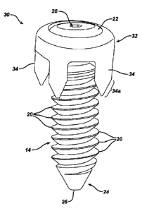
FIG. 2 provides an alternative spinal implant 30 wherein the stabilization
member 32 includes a plurality of features configured as column-shaped tines
34. As
shown, each tine 34 includes a tapered distal end 34a thereby facilitating
engagement of
the tine 34 to a portion of the facet joint. For example, the tine 34 can be
adapted to
wedge in between the screw 14 and an outer edge of the facet joint thereby
securing the
CA 02683774 2009-10-13
WO 2008/127978 PCT/US2008/059889
-9-
implant 30 to the joint. Like the embodiment of FIGS. lA-1D, the stabilization
member
32 can be adapted to include any number of tines 34 placed at any position
along the
circumference of the stabilization member 32. FIG. 3 provides another spinal
implant
40 having a stabilization member 42 with a plurality of tines 44. As shown,
the tines 44
are similar to the tines 34 of FIG. 2. However, the tines 44 of FIG. 3 are
configured with
smaller dimensions (e.g., width and length) as compared to the embodiment of
FIG. 2.
As such, the tines can be adapted to include any size and/or shape as required
so as to be
compatible with a target facet joint.
FIG. 4 provides another spinal implant 50 wherein the stabilization member 52
includes a plurality of tines 54 adapted to provide a substantially serrated
edge. The
serrated edge can engage and/or cut into an outer portion (or wall) of the
facet joint as
the implant 50 is positioned in an intra-facet orientation. Although the tines
54 are
shown to have a blunt distal-facing end, it is understood that this end of the
tine 54 can
be alternatively or additionally sharp.
As mentioned, embodiments of the spinal implant can also include more than one
type (or configuration) of feature incorporated into the same stabilization
member. For
example, FIG. 5 provides a spinal implant 60 having a stabilization member 62
which
incorporates tines of various sizes and/or configurations. More specifically,
the
stabilization member 62 includes at least one tine 64 and at least one tine 66
wherein the
tines 64, 66 are different. For example, the tines 64, 66 can be of different
sizes, shapes,
adapted to perform different functions, etc. In this embodiment, the first
tine 64 and
second tine 66 are similar in shape but distinct in size. As such, the larger
tines 64 can
be adapted to wedge between the screw 14 and a bony portion (e.g., an outer
edge) of
the facet joint while the smaller tines 66 can pierce the outer edge of the
facet joint. The
tines 64, 66 can also be adapted to vary in both size and configuration.
In other embodiments, the stabilization member of the implant 60 can be
configured in various alternative shapes and sizes as compared to those
substantially
circular embodiments discussed above. For example, as shown in FIG. 6, the
spinal
implant 70 can include a stabilization member 72 configured in a substantially
square
shape. Like above, the stabilization member 72 can include a plurality of
features 74
protruding therefrom capable of securing the implant to the desired anatomical
location.
Those skilled in the art will appreciate that in addition to substantially
circular and
CA 02683774 2009-10-13
WO 2008/127978 PCT/US2008/059889
-10-
square shapes, the stabilization member can be substantially oval,
rectangular, or any
other such shape and remain within the spirit and scope of the present
invention.
In addition to engaging and/or piercing a portion of the facet joint, various
embodiments of the spinal implant can include a stabilization member having a
feature
adapted to be positioned between the facet faces and adjacent the elongate
member. For
example, FIG. 7 provides a spinal implant 80 which includes a stabilization
member 82
having opposing features 84, 84' adapted to extend along the length of the
screw. As
shown, the features 84, 84' can be positioned on opposite sides of the
elongate member
as the member is positioned within the facet joint. As such, the features 84,
84' can
engage opposing facet faces thereby acting as a mechanical spacer. Further,
the features
84, 84' can each terminate in a tapered distal region 85, 85' adapted to
facilitate
placement of the implant 80 within the facet joint. Those skilled in the art
will
appreciate that these features 84, 84' can include any size, length, and/or
configuration
capable of being positioned as described above. Alternatively, the
stabilization member
82 can include only a single feature 84 adapted to be positioned between the
facet faces
and adjacent the elongate member.
Referring to FIG. 8, the stabilization member 90 can include features 92, 92'
adapted to be positioned between the facet faces and adjacent the elongate
member, and
also features 94 (e.g., tines) adapted to pierce an outer edge of the joint.
Like the
embodiments discussed above, such a stabilization member 90 can include any
number
of elongate features 92 in addition to any number and/or configuration of
second feature
94. As further illustrated in FIG. 8, the elongate features 92, 92' can have a
different
configuration as compared to the elongate features 84, 84' of FIG. 7. More
specifically,
the features 92, 92' are substantially rectangular in shape and maintain a
substantially
constant thickness along their length. Also, features 92, 92' terminate at
blunt distal
ends 92a, 92a' thereby facilitating stabilization of the implant within a
larger facet joint.
In addition to the various implants discussed above, the stabilization member
can
also be configured to include at least one lateral extension that can be in
the form of a
"plate-like" configuration, or it can be in the form of a tether or cable.
Such
embodiments can be utilized in either intra-facet and/or trans-facet
stabilization of the
facet joint. As will be discussed, a plate like configuration allows for at
least one lateral
extension to be positioned adjacent to an outer portion of a vertebra and
adapted to
CA 02683774 2009-10-13
WO 2008/127978 PCT/US2008/059889
-11-
secure the implant to the vertebra (e.g., via a fixation member, sharpened
prong, etc).
For example, FIGS. 9A and 9B provide a spinal implant 100 wherein the
stabilization
member 102 includes a first lateral extension 104a and a second lateral
extension 104b.
As shown, the lateral extensions 104a, 104b can be positioned on opposite
sides of the
elongate screw 14. In other embodiments, the stabilization member 102 can
include
only a single lateral extension 104a. In still other embodiments, the lateral
extensions
can be stacked relative to one another. As will be appreciated by those
skilled in the art,
the lateral extensions can include various other configurations relative to
one another
and remain within the spirit and scope of the present invention.
The first lateral extension 104a includes at least one opening 106a adapted to
receive a fixation member (e.g., a bone screw, a pin, etc.) thereby allowing
the fixation
member to pass through the lateral extension 104a and securely engage (e.g.,
screw into)
an underlying vertebra. Similarly, the second lateral extension 104b can also
include at
least one opening 106b adapted to receive a second fixation member thereby
allowing
the second fixation member to pass through the second lateral extension 104b
and
securely engage a second vertebra. For example, as the elongate member 14 is
positioned within the facet joint in an intra-facet configuration, the first
lateral extension
104a can reside adjacent a superior vertebra (positioned above the facet
joint) and the
second lateral extension 106b can be positioned adjacent an inferior vertebra
(positioned
below the facet joint). In addition to these lateral extension features 104a,
104b, the
stabilization member 102 can also include at least one tine 108 adapted to
engage an
outer edge of the facet joint.
FIGS. I OA-l OB provide another embodiment of the spinal implant 110 wherein
the stabilization member 112 again includes a first lateral extension 114a and
a second
lateral extension 114b. Like above, these embodiment can be utilized for trans-
facet
delivery in addition to intra-facet delivery. However, in this embodiment, the
first
lateral extension 114a is adapted to include at least one (or a plurality of)
pointed
protrusion(s) 116a capable of engaging a vertebra as the screw 14 is
positioned within
the facet joint. Likewise, the second lateral extension 114b is also adapted
to include at
least one (or a plurality of) pointed protrusion(s) 116b capable of engaging a
second
adjacent vertebra as the elongate member is positioned within the facet joint
in an intra-
facet configuration. Those skilled in the art will appreciate that various
other "plate-
CA 02683774 2009-10-13
WO 2008/127978 PCT/US2008/059889
-12-
like" embodiments are within the spirit and scope of the present invention.
Such lateral extensions can adopt a variety of configurations. For example,
the
extensions can be planar, curvilinear, etc. Additionally, the extensions can
be a
"formable" material (e.g. an in situ curing polymer composite system) thereby
allowing
the extension to adopt a variety of shapes. One skilled in the art will
appreciate that a
variety of formable materials can be used. Examples of such formable materials
can
include in situ curable polymers (e.g., polymethylmethacrylate (PMMA) putty),
superelastic alloys, shape memory materials, and braided cable.
The various stabilization members and feature(s) (e.g., tines, elongate
features,
plates, etc.) discussed above can include a wide-range of biocompatible
materials. For
example, the members and features can include various polymers or polymer
blends,
metals or metal alloys. With specific regards to the various features, these
elements can
include materials capable of piercing bone. Also, various features can be
formed from a
resilient material (e.g., a shape memory metal) thereby allowing the feature
to conform
to and/or "push back" against a facet face as the feature is wedged between
the elongate
member and the facet face (or outer edge of the facet joint). Also, as
mentioned above,
the stabilization member of the various embodiments can include a bioactive
fusion-
promoting material capable of actively participating in spinal fusion. For
example, those
features configured to be positioned within the facet joint (see FIGS. 7 and
8) can be
formed from such a bioactive material thereby allowing the implant to
participate in
spinal fusion. Additionally, all other implants discussed above can include a
portion (or
a coating) having the bio-active fusion promoting material.
The fusion-promoting bioactive material can include any material capable of
actively participating in spinal fusion. In an exemplary embodiment, the
bioactive
material can be allograft bone material (such as AllowashedTM available from
LifeNet,
Inc.; Virginia Beach, Virginia). In another example, the material can be a
bioresorbable
plastic (poly-lactic acid, polyglycolic acid, their derivatives and/or
blends), poly-
anhydride (PolymerDrugTM by PolyMerix, Piscataway, NJ), polymerized sugars or
starches (EurekaTM by Surmodics of Eden Prairie, MN), bioceramic (HIP VitoxTM
alumina or ZyranoxTM zirconia by Morgan Advanced Ceramics of Fairfield, NJ;
crystalline hydroxyapatite, tricalcium phosphates or combinations of these
materials by
Berkeley Advanced Biomaterials of San Leandro, CA), bioceramic-loaded
CA 02683774 2009-10-13
WO 2008/127978 PCT/US2008/059889
- 13 -
bioabsorbable material, or dense protein (NovasilkTM by Protein Polymer
Technologies
of San Diego, CA). Exemplary embodiments of such bioabsorbable materials
include
BiocrylTM (an 85% PLA/PGA, 15% tricalcium phosphate material available from
Depuy
Mitek, a Johnson & Johnson Company; Raynham, Massachusetts) or TriABSorbTM (a
5% hydroxyapatite, 95% PLA material available from Depuy Mitek, a Johnson &
Johnson Company; Raynham, Massachusetts) As another example, the material can
be
an osseointegrating polymer such as PEEK/OptimaTM (available from Invibio,
Inc.;
Greenville, South Carolina).Those skilled in the art will appreciate that any
combination
of these materials are within the spirit and scope of the present invention.
As will be
discussed below, the screw can also include such fusion-promoting material
thereby
providing various embodiments capable of providing both spinal fixation and
fusion.
The various spinal implants discussed above also include an elongate member
coupled to the stabilization member. The elongate member can include any such
member known to those skilled in the art. For example, the elongate member can
include a pin, a dowel, a plug, a beam, a post, a threaded post, a bolt, an
expansion
barrel, a pop-rivet, a staple, an anchor, a suture (attached to a deep anchor
or feature),
etc. In an exemplary embodiment, the elongate member is a screw. As will be
shown,
the screw 14 can be configured (e.g., length, width, major diameter, minor
diameter, etc)
for placement within a facet joint in an intra-facet configuration. In other
embodiments,
the screw can be adapted for trans-facet spinal fixation and stabilization. As
illustrated
in FIGS. IA-IC, the screw 14 includes a shank 15 extending between proximal 25
and
distal ends 24. A portion of the distal end 24 can include a conical tip 23
capable of
facilitating placement of the screw 14 within the facet joint. In one
embodiment, the
distal tip 26 can include a blunt surface. In other embodiments, the distal
tip 26 includes
a sharp point (not shown).
The proximal end 25 of the screw 14 can be adapted so as to prevent over-
insertion of the screw thereby substantially preventing injury resulting from
penetration
of the screw into the spinal column. As will be apparent to one skilled in the
art, the
proximal end 25 can be adapted in various ways to prevent such over-insertion.
For
example, as shown in FIGS. lA-1C, the proximal end 25 can include a screw head
22
extending from the proximal end of the shank, the head 22 having a diameter
greater
than a major diameter (D1) of the shank. Additionally, as discussed in detail
above, the
CA 02683774 2009-10-13
WO 2008/127978 PCT/US2008/059889
-14-
stabilization member and associated stabilization feature substantially
prevent over-
insertion of the implant by engaging portions of the stabilization member to
various
bony portions associated with the facet joint (e.g., facet faces, outer
portion of facet,
outer edge of facet, etc.). The screw head 22 can be a distinct element or can
be integral
with the screw. As discussed above, in an exemplary embodiment, the screw head
22
can be adapted to allow for polyaxial coupling of the stabilization member 12.
Those
skilled in the art will appreciate that various screw head 22 designs are
within the spirit
and scope of the present invention.
As further shown in FIGS. lA-1C, the shank 15 can have a thread 20 formed
thereon with a configuration such that a major diameter (Dl) and a minor
diameter (D2)
of the thread 20 can remain substantially uniform in the direction from the
distal tip 23
to the proximal end 25 of the shank 15. In another embodiment (not shown), the
major
diameter of the screw 100 can increase from the distal 24 to proximal end 25
of the
shank 15. The thread 20 can be continuous or non-continuous. In the exemplary
embodiment of FIGS. lA-1C, the thread 20 begins proximal to the distal tip 26
and
proceeds along substantially the entire length of the shank 15, terminating
before the
head 22. In an alternative embodiment, the thread 20 can extend along the
entire distal
end 24. One skilled in the art will appreciate that the thread 20 can be
configured to run
clockwise or counter-clockwise.
The threads can include various sizes and/or dimensions. In an exemplary
embodiment, the threads have a buttress cross-section, and a substantially
constant
thread crest height, thickness, and pitch along the length of the screw. In
one
embodiment, the root diameter of the screw can be proportional to the facet
distraction
distance after screw placement within the joint. Further, the thread depth
relates to bony
purchase and correlates to screw extraction strength. Such features can be
optimized for
stabilization of the facet joint via placement of the screw within the facet
joint in an
intra-facet configuration.
Various dimensions of the screw are within the spirit and scope of the present
invention. In an exemplary embodiment, the dimensions of the screw (e.g.,
length,
major diameter, minor diameter, etc.) are adapted for placement of the implant
within a
facet joint in an intra-facet or trans-facet configuration, whichever is
required for a
desired procedure. Referring to those embodiments utilizing intra-facet
placement, the
CA 02683774 2012-01-13
WO 2008/127978 PCT/US2008/059889
-15-
screw can have a length in the range of about 25mm to about 30mm, a major
diameter
(Di) in the range of about 4mm to about 12mm, and a minor diameter (DZ) in the
range
of about 2mm to about 8mm. Additionally, the distance between adjacent thread
heights
can be in the range of about 1mm to about 5mm. Those skilled in the art will
appreciate
that various screw dimensions are within the spirit and scope of the present
invention.
Referring to FIG. 113, the proximal facing surface of the screw head 22 can
include a drive feature 28 capable of receiving (or being received by) a
driver instrument
(e.g., a screwdriver) for delivery of the screw to the facet joint. The drive
feature 28 can
be of any suitable design as is known in the art. For example, the drive
feature 28 can be
a female drive feature, such as a hex-shaped socket, capable of seating a
complementary
male drive feature of a driver tool. Similarly, the drive feature 28 can be a
male feature
(not shown) capable of mating with a complementary female drive feature of a
driver
tool. Regardless of the shape or configuration of the drive feature 28, it
should be
effective to enable application of a torque along the entire shaft of the
screw using a
suitable driver tool.
As shown in FIG. 1C, the screw 10 can be a cannulated screw that includes an
inner lumen 29 that extends along its entire length. The lumen can be of any
suitable
diameter, but in one embodiment it is capable of receiving a Kirschner wire
("K-wire"),
which can serve as a guide-wire for delivery of the cannulated screw to the
facet joint.
In addition to the embodiments described herein, the screw can include a wide
range of geometries. For example, the screw can have an undulating geometry
wherein
either the minor diameter varies and the thread size remains substantially
constant, or the
minor diameter remains substantially constant and the major diameter varies
from
proximal to distal ends.
The elongate screw, like the stabilization member described' above, can be
adapted to allow for spinal fusion as well as spinal fixation. As such, any
portion of the
elongate screw can include or be formed of a fusion-promoting bioactive
material so that
the screw actively participates in spinal fusion. In an exemplary embodiment,
the screw
is made from the bioactive material. In another embodiment, a bioactive
material can be
CA 02683774 2009-10-13
WO 2008/127978 PCT/US2008/059889
-16-
formed as a coating on a non-bioactive material from which the screw is
formed. For
example, the screw can be formed of a metal or metal allow and be coated with
a fusion-
promoting bioactive material. In an alternative embodiment, the non-fusion
promoting
material (e.g., metal or metal alloy) can form a "cage-like" device capable of
housing
and releasing the fusion-promoting material. A benefit of these embodiments is
the
added stability provided by the non-fusion material.
Like above, the fusion-promoting bioactive material can include any material
capable of actively participating in spinal fusion. In an exemplary
embodiment, the
bioactive material can be allograft bone material (such as AllowashedTM
available from
LifeNet, Inc.; Virginia Beach, Virginia). In another example, the material can
be a
bioresorbable plastic (poly-lactic acid, polyglycolic acid, their derivatives
and/or
blends), poly-anhydride (PolymerDrugTM by PolyMerix, Piscataway, NJ),
polymerized
sugars or starches (EurekaTM by Surmodics of Eden Prairie, MN), bioceramic
(HIP
VitoxTM alumina or ZyranoxTM zirconia by Morgan Advanced Ceramics of
Fairfield, NJ;
crystalline hydroxyapatite, tricalcium phosphates or combinations of these
materials by
Berkeley Advanced Biomaterials of San Leandro, CA), bioceramic-loaded
bioabsorbable material, or dense protein (NovasilkTM by Protein Polymer
Technologies
of San Diego, CA). Exemplary embodiments of such bioabsorbable materials
include
BiocrylTM (an 85% PLA/PGA, 15% tricalcium phosphate material available from
Depuy
Mitek, a Johnson & Johnson Company; Raynham, Massachusetts) or TriABSorbTM (a
5% hydroxyapatite, 95% PLA material available from Depuy Mitek, a Johnson &
Johnson Company; Raynham, Massachusetts) As another example, the material can
be
an osseointegrating polymer such as PEEK/OptimaTM (available from Invibio,
Inc.;
Greenville, South Carolina).Those skilled in the art will appreciate that any
combination
of these materials are within the spirit and scope of the present invention.
The non-fusion promoting material can be any suitable biocompatible material.
For example, the non-fusion promoting material may be a metal or metal alloy.
In an
exemplary embodiment, the non-fusion promoting material is titanium or a
titanium
alloy (i.e., Ti 6A1 4V). Those skilled in the art will appreciate that various
other such
biocompatible materials are within the spirit and scope of the present
invention.
CA 02683774 2009-10-13
WO 2008/127978 PCT/US2008/059889
-17-
In addition to the spinal implants discussed above, a method for providing
stabilization and/or fusion to a facet joint is herein provided. Before
describing the
presently disclosed method, the following provides an overview of facet joint
anatomy
and prior art methods of providing spinal fixation to such joint. As such,
FIGS. 11-13
are an overview of the spinal column structure and location of associated
facet joints.
As FIG. 1 I shows, the human spinal column 150 is comprised of a series of
thirty-three
stacked vertebrae 152 divided into five regions. The cervical region includes
seven
vertebrae 152, known as CI-C7. The thoracic region includes twelve vertebrae
152,
known as T1-T12. The lumbar region contains five vertebrae 152, known as L1-
L5.
The sacral region is comprised of five vertebrae 152, known as S 1-S5. The
coccygeal
region contains four vertebrae 152, known as Col-Co4.
FIG. 12 shows a normal human lumbar vertebra 152. Although the lumbar
vertebrae 152 vary somewhat according to location, they share many features
common
to most vertebrae 152. Each vertebra 152 includes a vertebral body 154. Two
short
bones, the pedicles 156, extend posteriorly from each side of the vertebral
body 154 to
form a vertebral arch 158. At the posterior end of each pedicle 156 the
vertebral arch
158 flares out into broad plates of bone known as the laminae 160. The laminae
160
fuse with each other to form a spinous process 162, to which muscle and
ligaments
attach. A smooth transition from the pedicles 156 into the laminae 160 is
interrupted by
the formation of a series of processes.
Two transverse processes 164 thrust out laterally on each side from the
junction
of the pedicle 156 with the lamina 160. The transverse processes 164 serve as
levers for
the attachment of muscles to the vertebrae 152. Four articular processes, two
superior
166 and two inferior 168, also rise from the junctions of the pedicles 156 and
the
laminae 160. The superior articular processes 166 are sharp oval plates of
bone rising
upward on each side from the union of the pedicle 156 with the lamina 160. The
inferior
processes 168 are oval plates of bone that jut downward on each side. The
superior and
inferior articular processes 166 and 168 each have a natural bony structure
known as a
facet. The superior articular facet 70 faces upward, while the inferior
articular facet 172
faces downward. As shown in FIG. 13, when adjacent vertebrae 152, 152' are
aligned
(i.e., stacked), the facets interlock to form corresponding facet joints 180,
80' positioned
at the same level of the spine.
CA 02683774 2009-10-13
WO 2008/127978 PCT/US2008/059889
-18-
Looking in more detail at FIG. 13, the spinous process 162 and inferior
articular
processes 168 of the top vertebrae 152 are positioned adjacent to the superior
articular
processes 166 of the bottom vertebrae 152' and form facet joints 180, 180'. As
shown
in FIG. 14A, prior art trans-facet fixation procedure includes the insertion
of trans-facet
screws 182, 184 through bone and across the facet joints 180, 180'. However,
such a
procedure has been known to result in various problems. For example, FIG. 14B
shows
that a minor miscalculation in screw placement can result in a trans-facet
screw 182
impinging upon the spinal column (as indicated by (1)) and/or impinging upon
surrounding nerves (as indicated by (2)), thereby resulting in patient injury.
Additionally, trans-facet screw placement procedures can result in unwanted
and/or
unpredictable rotational distortion (or lateral offset) of the facet joint
because of the
difficulty of approximating the final position of the trans-facet screws 182,
184 in these
procedures. As shown in FIG. 14C, trans-facet placement of the screws 182, 184
can
result in significantly different gap sizes in corresponding facet joints 180,
180', thereby
resulting in unwanted tension on the spine and ultimately injury to the
patient. As
discussed, various embodiments of the spinal implant provided herein (e.g.,
the plate-
like embodiments shown in FIGS. 9A-IOB) can be utilized to improve such prior
art
trans-facet procedures.
FIG. 15 provides a representation of a first implant 10 being delivered to a
first
facet joint 180 in an intra-facet configuration, and a second implant 10'
being delivered
to a second, corresponding facet joint 180' (positioned at the same level of
the spine as
the first facet joint 180) in a similar intra-facet configuration. In this
representation, the
first 10 and second 10' implant are substantially identical. In other
embodiments, the
implants can be of different sizes (e.g., the first implant 10 larger than the
second
implant 10'), have different stabilization members, and/or different number,
types or
configurations of features incorporated into stabilization member. More
specifically,
any implant discussed above can be delivered to either corresponding facet
joint 180,
180' and remain within the spirit and scope of the present invention.
Furthermore, the
method can include the delivery of only a single implant to only one of the
corresponding facet joints 180, 180'.
CA 02683774 2009-10-13
WO 2008/127978 PCT/US2008/059889
-19-
FIG. 16A provides a representation showing the implants 10, 10' of FIG. 15
positioned within the facet joint in an intra-facet configuration. In other
embodiments,
the method includes delivering the implants to the facet joint in a trans-
facet orientation.
Referring to the intra-facet embodiments, as the implant 10 is positioned
within the facet
joint, the first tine 16 can be adapted to pierce a bony portion 200 of a
first vertebra
while a second tine 16' can be configured to pierce a bony portion 202 of a
second
vertebra thereby essentially acting as a staple to provide added stability to
the facet joint.
Also, as discussed above, the thread of the elongate member 14 can be
configured to
provide a desired amount of distraction to the joint. As shown, the second
implant 10'
can be similarly configured such that the first tine 16 of the second implant
10' pierces a
bony portion of the first vertebra 200' and a second tine 16' of the second
implant 10'
pierces a bony portion 202' of the second vertebra. In addition to the
embodiment
represented in FIG. 16A, the features (tines) can be configured to wedge
between the
elongate screw 14 and an outer edge(s) 200a, 202a of the facet joint. An
example of
such a tine was described in FIG. 2 (see element 34 and associated
discussion). FIG.
16B shows another view of the implant 10 being positioned within the facet
joint
(between adjacent vertebra, L1 and L2) wherein the stabilization member 12
engages a
bony portion 202 of vertebra L I and a bony portion 200 of vertebra L2 so as
to secure
the implant 10 within the facet joint in an intra-facet configuration. In each
embodiment, the tines can be adapted to contact (engage and/or pierce) various
anatomical structures such as bone, tissue, etc. Engaging any such structure
is within the
spirit and scope of the present invention.
FIG. 16C provides another embodiment of an implant(s) 80, 80' being positioned
within the facet joint in an intra-facet configuration. More specifically, the
implant 80
(shown and described in relation to FIG. 7) includes a stabilization member 82
having a
first feature 84 and a second feature (hidden from view) configured to extend
along a
substantial length of the screw 14 such that the first elongate feature 84 and
the second
elongate member 84' are positioned between the facet joints and adjacent to
opposite
sides of the elongate member. In these embodiments, the features 84, 84' can
act as
mechanical keys thereby contributing to stabilization of the joint. In
addition, forming
these features 84, 84' of a fusion/promoting material can allow for spinal
fusion as well
as fixation. In other embodiments, the elongate features can be wedged between
the
CA 02683774 2009-10-13
WO 2008/127978 PCT/US2008/059889
-20-
elongate screw and a corresponding facet face.
As an added benefit, the intra-facet spinal implant and procedures disclosed
herein are particularly well suited for minimally invasive surgery. That is,
crews or
similar devices can be positioned using one or more small, percutaneous
incisions, with
or without the need for an access port. Such procedures, which are generally
well
known to those skilled in the art, tend to result in less operative trauma for
the patient
than a more invasive procedures. Minimally invasive procedures also tend to be
less
expensive, reduce hospitalization time, causes less pain and scarring, speed
recovery,
and reduce the incidence of post-surgical complications, such as adhesions.
One skilled in the art will appreciate further features and advantages of the
invention based on the above-described embodiments. Accordingly, the invention
is not
to be limited by what has been particularly shown and described, except as
indicated by
the appended claims. All publications and references cited herein are
expressly
incorporated herein by reference in their entirety.
What is claimed is: