Note: Descriptions are shown in the official language in which they were submitted.
CA 02685168 2009-11-09
- 1 -
Input Device and Method of Detecting a User Input with an Input
Device
Field of the Invention
The invention relates to an input device and a method of detecting a user
input with an input device, and more particularly to an input device
comprising a multi-touch sensing display. The invention further relates to an
audio console comprising at least one inventive input device.
Background of the Invention
Modern electronic devices often require a plurality of control elements for an
adjustment of parameters. An input unit for such an electronic device may
be provided in the form of a console on which a plurality of mechanical
control elements are arranged. Such an input device may be used to control
for example audio equipment, video equipment, or a central control station
for e.g. a power plant, a factory, or a traffic system, and the like. Control
elements employed in these systems are often analogue elements with a
predefined functionality. Accordingly, applications of such an input device
are limited as the functionality cannot be changed or adjusted. In the case
where control elements in the form of encoders, such as rotary encoders, are
provided, the functionality may be changed, yet the problem arises that it is
difficult to recognize which functionality is currently assigned to the
control
element. This is particularly the case if the functionality and the value of
an
associated parameter is displayed on a separate screen distant from the
control element.
CA 02685168 2009-11-09
- 2 -
Complex electromechanical input elements, such as rotary encoders, further
suffer from the drawback that they are complex and expensive, as well as
difficult to mount. Mounting such an element requires a fair amount of
space underneath the cover plate of the input device, and is further time and
cost intensive. This is particularly a drawback for large input consoles
comprising e.g. tens or hundreds of control elements.
Further, touchscreens are known in the art as input devices. These are often
implemented in compact electronic devices, such as personal digital
assistant (PDA) or more recently mobile phones. Several technologies for
detecting a touch or a near touch to a surface are known in the art.
Examples are a resistive touchscreen panel composed of several layers,
wherein the layers are contacted at a certain point upon touching. A change
in the electrical current through the layers is detected as a touch event and
a controller derives the position on the panel where the touch has occurred.
Further technologies comprise a capacitive touchscreen panel wherein a
distortion of an electromagnetic field is detected, or frustrated total
internal
reflection (FTIR), wherein the disturbance of a reflection light path internal
to
a glass plate providing a sensitive surface is detected upon pressing an
object against the surface. These touchscreens can be operated with objects
like a finger or a pen, wherein e.g. a capacitive touchscreen already triggers
an input event if an object comes to within a predetermined distance of the
touchscreen surface (near touch). Conventionally, these touchscreens were
only capable of detecting a single touch at a time. More recently,
touchscreens were developed which are capable of detecting simultaneous
multiple touches as separate input events. With such a multi-touch screen,
a user is enabled to use two fingers to simultaneously manipulate two
objects. Even though the aforementioned touchscreens provide a very flexible
input means, they are not suited for setting a larger number of parameters.
CA 02685168 2009-11-09
- 3 -
They are generally small sized and operated by one hand only. The
adjustment of a graphical control element on the touchscreen, e.g. with a
finger or a pen, further requires substantial motorical skills from a user and
is rather imprecise. A graphical control element requires a substantial
amount of space on the screen, thus preventing a provision of a plurality of
such elements. A plurality of small control elements would be difficult and
time-consuming to operate. Adjusting a plurality of parameters with a
conventional touchscreen is thus not ergonomic, particularly if such
adjustments have to be performed over a prolonged time.
Accordingly, there is a need to provide an input device which allows a
flexible
adjustment of parameters in an ergonomic manner. It is further desirable
that such an input device provides a precise adjustment of parameters and
is capable of informing a user which parameter is currently adjusted.
Hardware and mechanics of such an input device should be kept simple,
and the assembly should be cost efficient.
Summary of the Invention
Accordingly, there is a need to overcome or mitigate at least some of the
above-mentioned drawbacks.
This need is met by the features of the independent claims. The dependent
claims describe embodiments of the invention.
According to a first aspect of the invention, an input device comprising a
multi-touch sensing display adapted to detect multiple simultaneous
touches or near touches to a surface of the multi-touch sensing display as
distinct input events is provided. The input device comprises at least one
mechanical control element arranged on the surface of the multi-touch
CA 02685168 2009-11-09
- 4 -
sensing display. The at least one mechanical control element is configured
such that an actuation of the at least one mechanical control element
generates an input event which is detected by the multi-touch sensing
display.
Using such an input device, a precise adjustment of a parameter associated
with the mechanical control element can be achieved. As the control element
is mechanical and can physically be actuated by a user, the user is enabled
to make precise adjustments in an ergonomic way. Further, the mechanical
control element can be compact and is still easy to use. As the mechanical
control element may provide the input to the touchscreen, it can be freely
configured, i.e. its functionality may be adjusted as desired. Even further,
in
such a configuration, it is possible to display the present functionality of
the
mechanical control element on the multi-touch sensing display in proximity
to the control element. Thus, a user is enabled to immediately identify the
functionality, thereby preventing confusion or a mix-up. This is particularly
advantageous for applications where a multitude of control elements needs
to be provided. Not only is it possible to display information in proximity to
the control element with such an input device, but the area surrounding the
control element is touch-sensitive, thus providing an additional possibility
for a user input. As the display is multi-touch sensing, it may be capable of
detecting a simultaneous actuation of the control element and an input by
touching the surface. Even further, the configuration of the input device with
a multi-touch sensing display enables the arrangement of a plurality of
mechanical control elements on the surface, which may be simultaneously
actuated. Accordingly, an ergonomic adjustment of a plurality of parameters
can be achieved with the input device. The functionality of control elements
of the input device may be adjusted as desired, while still enabling a user to
associate a particular functionality with the respective control element.
CA 02685168 2009-11-09
- 5 -
According to an embodiment of the invention, the at least one mechanical
control element can be mechanically mounted to the surface of the multi-
touch sensing display. Mechanically mounting the control element may
comprise but is not limited to adhering the control element to the surface,
e.g. using an adhesive, inserting one or more bolts into cavities or holes on
the surface of the display, engaging or latching the control element with a
structure on the surface, and the like. Mounting the mechanical control
element in such a way has the advantage that it can be securely fixed to the
surface, while requiring only little effort. Accordingly, the control element
can time and cost efficiently be mounted to the surface. Mounting is further
facilitated as the control element can have a very simple structure or design
and may not require additional space underneath the surface of the multi-
touch sensing display. Further, no additional support structures may be
required on the surface, such as mounting bars or beams running across
the surface. Even though the mechanical control element is mounted to the
surface, the display and touch-sensitive area of the multi-touch sensing
display can be kept large, as only a small area may be covered by the control
element.
According to another embodiment, the input device comprises at least two
mechanical control elements, wherein the multi-touch sensing display is
adapted to detect a simultaneous actuation of the at least two mechanical
control elements as separate input events. With such an input device, two or
more parameters may be simultaneously adjusted. A great versatility of the
input device is thus achieved.
According to a further embodiment, the at least one mechanical control
element comprises a trigger element. When the trigger element touches the
surface at a position or comes within a predetermined distance of the
surface at the position, the trigger element triggers the input event at said
CA 02685168 2009-11-09
- 6 -
position on the surface. The multi-touch sensing display is adapted to detect
the position at which the input event is triggered. Using such a trigger
element, a precise adjustment of a parameter associated with the
mechanical control element may be achieved. It should be clear that if the
trigger element is held at a position at which an input event is triggered,
this
may also be detected by the multi-touch sensing display, so that the actual
position and thus the state of the control element may be determined.
Configuring the multi-touch sensing display and the trigger element in such
a way that an input event already occurs a predetermined distance of the
surface has the advantage that the trigger element does not need to touch
the surface, whereby frictional forces and abrasion of the display surface and
the trigger element may be prevented.
The control element may comprise a movable component. The trigger
element may then be arranged on the movable component such that when
actuating the control element by moving the movable component, the multi-
touch sensing display detects the movement of the trigger element relative to
the surface. The control element may for example comprise an element
fixedly mounted to the surface, the movable component being movable
relative to said fixed component. When moving the movable component and
thus the trigger element, successive input events may be triggered, which
may enable a determination of the positioning of the movable component.
With such an arrangement, a plurality of different types of control elements
with different degrees of freedom can be realized.
As an example, the movable component may be formed so that when
actuating the control element, the trigger element is moved in a plane
substantially parallel to the surface at a distance to the surface at which it
triggers an input event. Input events are then successively triggered for
different positions on the surface. Using such an arrangement, control
CA 02685168 2009-11-09
- 7 -
elements in form of a slider, a turn button, and others may be realized. As
the positioning of such a control element may be simply read out by the
multi-touch sensing display, the control element may not require any
additional mechanical or electrical components, thus enabling the realization
of plural more or less complex control elements with simple mechanics.
According to another example, the movable component may be formed so
that when actuating the control element, the trigger element is moved
substantially perpendicular to the surface between a position with a first
distance to the surface and a position with a second distance to the surface
chosen such that the movement of the trigger element triggers the input
event. With such a design, a push button, a rocker, a joystick like element,
or a similar control element may be realized. Again, such an element may
have a very simple mechanical structure. It should be clear that the input
device may comprise both an element wherein the trigger element is moved
in a plane substantially parallel to the surface and an element wherein the
trigger element is moved substantially perpendicular to the surface. Of
course, it is also possible to combine both types of movement in a control
element.
According to another embodiment, the input device further comprises a
processing unit. The multi-touch sensing display is adapted to detect a
position of the input event generated by said control element, and the
processing unit is adapted to assign a value to a parameter controlled by
said mechanical control element in dependence on the position at which the
input event was detected. Accordingly, the setting of the control element can
be easily determined by making use of the capability of the multi-touch
sensing display to determine the position of an input event. A precise
adjustment of the parameter value may thus be enabled.
CA 02685168 2009-11-09
,
,
- 8 -
The input device may be connected to an audio mixing device. The above-
mentioned parameter may then control a function of the audio mixing
device. As audio mixing devices generally require the adjustment of a
multitude of parameters, using the input device to control functions of the
audio mixing device is advantageous. This is particularly true as the input
device may be adapted to display the functionality and a parameter value
associated with a particular control element on said multi-touch sensing
display. Thus, in the case where a plurality of control elements is provided
on the input device, an efficient configuration of the input device can be
performed and an ergonomic adjustment of parameters for the audio mixing
device can be achieved.
According to a further embodiment, the multi-touch sensing display
comprises one of a capacitive touchscreen panel, an inductive touchscreen
panel, or a total internal reflection based touchscreen panel. Such
touchscreen panels may be adapted to detect simultaneous touches and may
be used with the present invention.
According to yet another embodiment, the multi-touch sensing display
comprises a display unit with an integrated array of optical sensors. The
display unit may for example be a liquid crystal display (LCD) unit. The
optical sensors may be capable of detecting touches or near touches to the
surface. As a large number of sensors may be arranged in the display unit
with relatively small spacing in-between them, a high resolution for the
detection of simultaneous touches or near touches can be achieved. Further,
in such a configuration, the upper surface of the multi-touch sensing display
may be manufactured out of a scratch resistant transparent surface, such
as glass. Such a surface may further facilitate the mounting of a mechanical
control element.
CA 02685168 2009-11-09
- 9 -
The multi-touch sensing display may be adapted to display an indication
regarding a value or a type of a parameter controlled by the mechanical
control element within a predetermined region adjacent to the mechanical
control element. The association of a particular functionality with a control
element and the adjustment of a parameter value are thus facilitated.
According to another aspect of the invention, a method of detecting a user
input with an input device comprising a multi-touch sensing display adapted
to detect multiple simultaneous touches or near touches to a surface of the
multi-touch sensing display as distinct input events and at least one
mechanical control element arranged on the surface of the multi-touch
sensing display is provided. According to the method, an input event is
generated in response to an actuation of the at least one mechanical control
element, and the input event is detected by the multi-touch sensing display.
A parameter associated with the at least one mechanical control element is
adjusted in accordance with the detected input event. Similar advantages as
outlined above with respect to the input device are also achieved with the
inventive method of detecting a user input.
According to an embodiment, at least two mechanical control elements are
provided on the input device, the method comprising a detecting of at least
one separate input event for each of the at least two mechanical control
elements in response to a simultaneous actuation of the least two
mechanical control elements. In accordance with the input event detected for
the respective mechanical control element, a parameter associated with the
mechanical control element is adjusted. Such a method may enable a
simultaneous control of a plurality of parameters with the input device.
The detecting of an input event may comprise a determining of a position on
the surface of the multi-touch sensing display at which the input event
CA 02685168 2009-11-09
- 10 -
occurred and a determining of a setting of the parameter associated with the
mechanical control element on the basis of the determined position. A
setting of a parameter may thus be simply adjusted by making use of the
capability of the multi-touch sensing display to determine a position at
which a touch or a near touch occurred.
According to a further embodiment, the actuation of the control element
comprises a moving of a trigger element arranged on the control element
relative to the surface. An input event is generated by reflecting and/or
scattering light off the trigger element onto optical sensors in response to
the
moving of the trigger element. The optical sensors are provided in the multi-
touch sensing display adjacent to the surface. The detecting of an input
event comprises a detection of said light by the optical sensors. As an
example, an array of photosensitive elements may be arranged underneath
the surface. The trigger element may then be a reflecting or absorbing
element, a movement of which relative to the surface will be detected by a
change of the intensity of light detected by particular photosensitive
elements. The position or a change in position of the trigger element may
thus be determined. With such a method, an adjustment of the parameter
with high resolution without contact between the surface and the trigger
element can be achieved.
According to a further embodiment, the actuation of the control element
comprises a moving of a trigger element arranged on the control element
relative to the surface. The generating of an input event comprises a
disturbing of an electrical field established adjacent to the surface by the
movement of the trigger element. The detecting of the input event comprises
a detecting of a position at which the disturbance of the electrical field
occurred. Such a method may for example by performed by using a multi-
touch sensing display comprising a capacitive touchscreen panel.
CA 02685168 2009-11-09
- 11 -
According to another aspect of the invention, an audio console comprising at
least one of the above-mentioned input devices is provided. Such an audio
console has the advantage that a plurality of parameters can be effectively
and ergonomically adjusted.
In an embodiment of the audio console, the input device comprises a
plurality of mechanical control elements arranged in an array and regions
sensitive to simultaneous touches or near touches between said elements.
The multi-touch sensing display is further configured to display information
relating to parameters associated with the plurality of mechanical control
elements in the regions. It may for example display a type and a value of a
parameter associated with a control element next to the control element. The
control elements are thus easily configurable, whereas relevant information
relating to associated parameters is provided to a user. The user may further
effectuate further user inputs by making use of the touch-sensitive areas
adjacent to the control elements. A very comprehensive and flexible control
of the audio console can thus be achieved.
It is to be understood that the features mentioned above and those yet to be
explained below can be used not only in respective combinations indicated,
but also in other combinations or in isolation, without leaving the scope of
the present invention.
The foregoing and other features and advantages of the invention will
become further apparent from the following detailed description read in
conjunction with the accompanying drawings. The detailed description and
drawings are merely illustrative of the invention rather than limiting.
CA 02685168 2009-11-09
- 12 -
Brief Description of the Drawings
Embodiments of the present invention are illustrated by the accompanying
figures, wherein
Fig. 1 is a schematic drawing of an input device according to an
embodiment of the invention;
Fig. 2 is a schematic drawing of an input device according to an
embodiment of the invention comprising a rotary knob as a
mechanical control element;
Fig. 3 is a schematic drawing of an input device according to an
embodiment of the invention comprising a sliding controller as a
mechanical control element;
Fig. 4 is a schematic drawing of an input device according to an
embodiment of the present invention comprising a push button
as a control element;
Fig. 5 is a schematic drawing illustrating an input device according
to
an embodiment of the invention using photosensitive elements
for detecting an actuation of a control element;
Fig. 6 is a schematic drawing illustrating an input device according to
an embodiment of the invention using a capacitive element for
triggering an input event;
Fig. 7 is a flow diagram illustrating a method according to an
embodiment of the invention;
CA 02685168 2009-11-09
- 13 -
Fig. 8 is a schematic drawing showing an audio console according to
an embodiment of the present invention.
Detailed Description
It is to be understood that the following description of embodiments is given
only for the purpose of illustration and is not to be taken in a limiting
sense.
It should be noted that the drawings are to be regarded as being schematic
representations only, and elements in the drawings are not necessarily to
scale with each other. Rather, the representation of the various elements is
chosen such that their function and general purpose become apparent to a
person skilled in the art.
Fig. 1 shows an embodiment of an inventive input device 100. The input
device 100 comprises a multi-touch sensing display 101 and two mechanical
control elements in form of two rotary knobs 102 and 103. These are fixedly
mounted to surface 104 of the multi-touch sensing display 101. Below
surface 104, display 101 comprises an array of optical sensors or
photosensitive elements shown as line 105. The display 101 may for example
comprise a thin film transistor (TFT) LCD display. The design of a TFT LCD
display with integrated photosensitive elements is known in the art and
details can be found e.g. in the document type titled "Active matrix LCD with
integrated optical touchscreen", www. planar. com / advantages/ whitepapers/
docs/planar-AMLCD-Optical-Touchscreen.pdf. Light emitted by the display
101 may be absorbed, scattered or reflected by trigger elements 106 and
107. If one of the control elements 102 and 103 is actuated by turning, the
intensity of light reflected onto photosensitive elements located underneath
the trigger element at the previous and the new position of the trigger
element changes, thereby generating an input event. Such an input event
can be detected by the multi-touch sensing display 101 in form of a change
CA 02685168 2009-11-09
- 14 -
of a photocurrent or a change of a current through the photosensitive
elements.
It should be clear that the multi-touch sensing display may not only be
adapted to generate a position dependent signal in response to an input
event, but that it may also comprise means for determining the position on
its surface where the input event has occurred, e.g. a processor and the like.
As such, the multi-touch sensing display may deliver a signalling
corresponding to sensor data out of which a processing unit determines an
occurrence and position of an input event, or it may directly deliver the
position of a detected input event, e.g. in form of two dimensional (e.g. x
and
y) coordinates relative to the surface. The setting of the control element
originating the input event may then be determined by a downstream
processing unit. It is thus only important that the multi-touch sensing
display is capable of resolving the position at which an input event occurred.
Processing unit 108 interfaces multi-touch sensing display 101. Processing
unit 108 both provides the display signal to display 101 and reads out the
array of photosensitive elements of display 101. A readout may be performed
at predetermined times, at which processing unit 108 obtains an image of
light intensities detected by the photosensitive elements at respective
positions on surface 104 of display 101. By analyzing the so obtained image
data, processing unit 108 can determine a position in the data at which a
change in intensity occurred. Processing unit 108 is provided with
information at which position what type of control element is located, and
which function is currently assigned to the respective control element. By
determining the position of an input event and thus the position of the
trigger element relative to the surface 104, the processing unit 108 can
determine the setting of the control element and assign a corresponding
value to a parameter of the function controlled by the control element. It
CA 02685168 2009-11-09
- 15 -
should be clear that a particular setting of the control element does not need
to correspond to a particular value of an associated parameter, but that an
activation of the control element by e.g. rotation through a particular angle
may define a corresponding change of the parameter value.
Thus, the actual position of trigger elements 106 and 107 can be detected by
the photosensitive elements of the multi-touch sensing display 101 and
determined by processing unit 108. Not only can input device 100 detect
simultaneous actuation of control elements 102 and 103 as separate or
distinct input events, i.e. can resolve the positions relative to the surface
at
which the input events occurred, but it is also capable of detecting a touch
or a near touch to surface 104 in areas of display 101 not covered by the
control elements and provided with said optical sensors. Further, processing
unit 108 can control display 101 to display e.g. the type and the value of the
parameter controlled by control element 102 or 103 next to the respective
control element. As in the present embodiment, optical sensors are used,
surface 104 may be a glass surface and accordingly, rotary knobs 102 and
103 may be simply mechanically mounted to surface 104, e.g. by using an
adhesive.
Parameter values adjusted with control elements 102 and 103 are provided
to audio mixing device 109. Audio mixing device 109 comprises plural audio
inputs 110 and outputs 111 for audio signals. Audio mixing device 109
processes the audio signals 110 in accordance with parameters received
from processing unit 108. Audio mixing devices, e.g. a digital mixer, are
known in the art and will not be further elaborated here.
Although the above embodiment has been described with respect to a multi-
touch sensing display comprising optical sensors, it should be clear that
other means of detecting input events such as capacitive or resistive
CA 02685168 2009-11-09
- 16 -
touchscreen panels or the like may be used. Further, parameter values may
be provided to any type of device by processing unit 108, such as a control
station for a machine, a power plant, or any other electronic device, such as
a computer or a station for video processing. Display 101 of input device 100
may thus not only display information relating to the function controlled by
a control element, but also data and information provided by a device
connected to input device 100.
Fig. 2 shows a mechanical control element 201 in form of a rotary knob
which can be turned in two directions as indicated by arrow 202. Rotary
knob 201 comprises a movable component 203 and a shaft with base 204
fixedly mounted to surface 205 of the multi-touch sensing display 206. Shaft
and base 204 are mounted by an adhesive to surface 205. Moveable
component 203 can be rotated on the shaft 205, thereby moving trigger
element 207 in a plane substantially parallel to surface 205. The distance
between the trigger element 207 and surface 205 is chosen such that its
position can be detected by the multi-touch sensing display 206. As a result,
turning the rotary knob 201 generates subsequent input events at positions
lying on a circle around the rotary axis 208 of the rotary knob 201.
In the embodiment of Fig. 3, the input device comprises a mechanical
control element in form of sliding controller 301. Movable component 303
can be moved linearly in a direction horizontal with respect to surface 305 of
the multi-touch sensing display 306 (arrow 302). Moveable component 303
is slidably received in support structure 304 fixedly mounted to surface 305.
As mentioned above, there are several possibilities of mounting support
structure 304 to surface 305 including glueing or cementing, engaging
elements of the support structure with a recess formed on the surface 305,
providing one or more holes through display 306 and attaching the support
structure by bolts, and the like. Actuation of the control element 301 results
CA 02685168 2009-11-09
- 17 -
in a movement of the trigger element 307 fixed to movable component 303 in
a horizontal direction relative to surface 305. The spacing between trigger
element 307 and surface 305 is again chosen such that the position of
trigger element 307 can be detected by the multi-touch sensing display 306.
The spacing will depend on the particular detection mechanism employed.
When using optical sensors or a capacitive touch screen panel, trigger
element 307 may not touch surface 305, whereas for a resistive touchscreen
panel or a method based on total internal reflection, trigger element 307 may
touch surface 305. Actuation of the sliding control 301 results in the
generation of input events at positions on surface 305 lying along a line. By
detecting the positions of the input events, the movement of the sliding
controller 301 can be inferred, and a value of an associated parameter can
be changed accordingly.
Another embodiment of an inventive input device is shown in Fig. 4, where
the movable component 403 of push button 401 can be moved in a direction
indicated by arrow 402 substantially perpendicular to surface 405 of the
multi-touch sensing display 406. Movable component 403 of push button
401 is supported by supporting structure 404 fixedly mounted to surface
405. When actuating the control element 401 by applying pressure to the
movable component 403, the distance between the trigger element 407
provided on the movable component 403 and the surface 405 is decreased,
whereby an input event is triggered. Again, depending on the type of multi-
touch sensing display, the distance in the pushed state of push button 401
may be such that trigger element 407 is located a predetermined distance
from surface 405 or touches surface 405. As an example, the intensity of
light detected by optical sensors underneath surface 405 may increase or
decrease in the pushed position, without the necessity of the trigger element
407 touching the surface. This does not preclude that in the non-actuated
state, the multi-touch sensing display 406 is capable of determining the
CA 02685168 2009-11-09
- 18 -
position of trigger element 407. It is just important that trigger element 407
generates an input event when push button 401 is actuated.
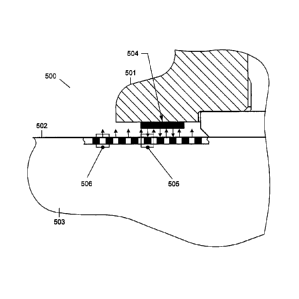
The embodiment of Fig. 5 illustrates the use of optical sensors for detecting
the positioning of a trigger element. The input device 500 of Fig. 5 comprises
a control element in form of rotary knob 501. Rotary knob 501 is mounted to
surface 502 of the multi-touch sensing display 503. Display 503 comprises
photosensitive pixels 505 (shown as black squares) and display pixels 506
(shown as white squares). For displaying an image, display pixels 506 emit
light, as indicated by arrows. The emitted light is now reflected by the
reflective trigger element 504 mounted to the rotary knob 501. The reflected
light is detected by the photosensitive pixels 505 (as indicated by arrows).
Accordingly, the position of the reflective trigger element 504 relative to
surface 502 can be detected by the photosensitive pixels 505 and determined
by reading out the detected intensity values and analyzing the intensity
distribution. In such a configuration, it may be particularly beneficial to
design the remaining surface of the control element 501 facing surface 502
to be non-reflective, i.e. absorptive, for the light emitted by display 503.
Further, it may be advantageous to control the emission of light by the
display pixels located in the area of surface 502 over which the trigger
element 504 may be moved such that they emit light with a predetermined
intensity, e.g. near maximum intensity, so that a high signal is received from
photosensitive pixels 505 and a precise determination of the positioning of
the trigger element is achieved. It should be clear that other implementations
are also conceivable, such as providing an absorptive trigger element and a
reflective surface of the control element 501 facing the surface 502 of the
display 503.
In the embodiment of Fig. 6, the input device 600 comprises at least one
control element, such as rotary knob 601. The multi-touch sensing display
CA 02685168 2012-01-23
- 19 -
603 comprises a capacitive touch-screen panel with a capacitive sensitive
layer 605. The functioning of a capacitive multi-touch sensing display is
known to a person skilled in the art and will not be explained in further
detail here. Details on a capacitive multipoint touchscreen can for example
be found in the US Patent Publication US 2006/00917991 A1.
A conventional capacitive touchscreen panel may for example comprise a
capacitive sensing layer of a metal oxide, such as indium tin oxide, which
conducts an electrical current across the sensor panel which is applied by
electrodes on each corner of the panel. As an example, a square wave voltage
may be applied. When a panel is touched, a charge transport occurs, which
can be measured in form of a current at the corners of the panel. The
position of the touch event can be determined by evaluating the resulting
currents at the corners of the panel. To detect multiple simultaneous
touches, the touchscreen panel may comprise a plurality of transparent
sensor nodes which may again be formed of a conductive medium such as a
metal oxide, spatially separated into electrodes and traces. Different
coordinates on the display may then be represented by the different
electrodes, and the traces are used to connect the electrodes to a capacitive
sensing circuit. Accordingly, a change of a capacitance occurring at a
particular electrode can be recognized, and by using a plurality of
electrodes,
the positions of simultaneously occurring touches can be resolved. For
triggering an input event, the capacitive trigger element 604 is provided. An
electrical field established adjacent to a sensing node of capacitive
sensitive
layer 605 at a position underneath the trigger element 604 is disturbed by
the trigger element, which can be detected as a change in capacitance at the
sensing node. Accordingly, the position of trigger element 604 relative to
surface 602 can be determined. Actuation of control element 601 results in a
change of capacitance of another sensing node, which again generates an
CA 02685168 2009-11-09
- 20 -
input event the position of which relative to surface 602 can be determined
by a capacitive sensing circuit. Capacitive trigger element 604 may be
grounded, or may be grounded when a user touches control element 601. It
is further conceivable to arrange sensing nodes of the capacitive multi-touch
sensing panel such that a high resolution of the positioning of trigger
element 604 is achieved, e.g. by closely spacing them in proximity of the
control element. Again, multi-touch sensing display 603 is capable of
sensing a simultaneous actuation of control element 601 and a touch to
surface 602, as well as of displaying information.
Fig. 7 shows a flow diagram of an embodiment of a method according to the
invention. The method may be performed by e.g. using the input device of
Fig. 1 or Fig. 5. In step 701, two control elements are actuated
simultaneously. It should be clear that these could be any types of control
elements, such as rotary knobs, sliders, rockers, push buttons, and the like.
By actuating the control elements, trigger elements of the control elements
are moved relative to the display surface (step 702). Optical sensors located
in the display detect light emitted by the display and reflected by the
trigger
elements. Due to the movement of the trigger elements, a change of the
intensity of the light detected by the optical sensors occurs, which is
detected in step 703. On the basis of the detected intensity changes, the
locations or positions on the display at which the intensity changes occurred
are determined in step 704. A new setting of each control element is derived
in step 705 on the basis of the respective intensity change and its location.
It
may for example be found that a slider was moved a particular distance or
that a rotary knob was turned through a particular angle. On the other
hand, the absolute setting of the control element may be determined, such
as the new position of a slider or of a rotary knob. A new value for a
parameter associated with the control element is then calculated in step 706
on the basis of the derived new setting for each control element. As an
- .
CA 02685168 2009-11-09
- 21 -
example, a particular switching function may have been assigned to a push
button, and an associated parameter value may be changed from '1' for an
on position to a '0' for an off position upon actuation. The parameter value
may also be adjusted according to a determined travel distance or turn angle
of a control element, or to the determined absolute new setting of the control
element. The parameters with their values are then provided to a device
connected to the input device in step 707. It should be clear that the above
method may comprise further steps, such as detecting a touch to a surface
adjacent to a control element and adjusting a parameter on the basis of the
detected touch, or changing the functionality of a control element in
accordance with a position of a detected touch or the like. As such, graphical
control elements may be provided, according to which the functionality of
the mechanical control elements may be changed.
Fig. 8 shows an audio console according to an embodiment of the invention
implementing two input devices 801 and 802 according to embodiments of
the invention. Input device 801 of audio console 800 comprises plural
mechanical control elements in form of rotary buttons 803. The input
devices are shown in a view from above, as indicated in Fig. 2 by arrow 205.
The portions of input devices 801 and 802 visible to a user are touch-
sensitive and are operative to display information. Areas 804, 805 and 806
adjacent to rotary knobs 803 are used to display the type of parameter and
the parameter value currently adjusted by the respective rotary knob. In the
present example, area 804 indicates the adjustment of a numerical value for
a particular channel, area 805 indicates the adjustment of a high frequency
equalizer using a needle indicator, whereas area 806 indicates the
adjustment of a bandwidth.
Input device 802 comprises sliding controls 807 and 808. These may for
example be faders, with graphical indications on a channel to be adjusted
CA 02685168 2009-11-09
- 22 -
and of a present setting provided next to them. Further, push buttons 809
and 810 are provided, again with their present setting indicated graphically
in an area adjacent to them. Although control elements 807 to 810 are
mechanical control elements in the present embodiments, it should be clear
that some of these may also be implemented as graphical control elements,
which may be actuated by touching the surface of input device 802 at a
position where the control element is displayed.
A person skilled in the art will appreciate that different types of mechanical
and graphical control elements may be arranged on a touch-sensitive surface
of the input device, and that mechanical control elements other than the
ones mentioned above are conceivable. Apart from being used in an audio
console 800, input devices according to embodiments of the invention may
also be implemented in other devices such as control stations of a factory or
a power plant. As mentioned above, the invention is particularly
advantageous for devices requiring a large number of parameters to be
adjusted, preferably with a flexible configuration of the control elements.
The skilled person will further recognize that types of multi-touch sensing
displays different from the ones mentioned above may be used with the
present invention. Examples are infrared touchscreen panels, strain gauge
touchscreen panels, surface acoustic wave or diffused laser imaging
touchscreen panels, and the like. These panels should be adapted so as to
recognize multiple simultaneous touches.
While specific embodiments of the invention are disclosed herein, whereas
changes and modifications can be made without departing from the spirit
and the scope of the invention. The present embodiments are to be
considered in all respect as illustrative and non-restrictive, and all changes
CA 02685168 2009-11-09
- 23 -
coming within the meaning and equivalency range of the appended claims
are intended to be embraced therein.