Note: Descriptions are shown in the official language in which they were submitted.
- 1 -
IMPROVEMENTS TO RESUSCITATORS
FIELD
The present invention relates to improvements to resuscitators.
BACKGROUND
Resuscitators that can supply pressurised air or oxygen to a patient are well-
known.
Examples include bag or bellows type resuscitators and pump-like resuscitators
and
pressure-limited resuscitators. However, there are limitations in certain
resuscitators.
For example, there is a risk of overinflating a patient's lungs by delivering
a volume of air
that is greater than desirable. There is also a risk the pressure of the air
or oxygen
delivered may be at undesirably high levels. Such undesirable characteristics
of the air
being delivered to the patient can have adverse affects on the patient. If a
patient's airway
passage is or becomes blocked and air is delivered by the known devices then
undesirable
pressures may be reached. Further such increased pressure may cause sudden
dislodgement of the blockage and may lead to serious consequences for the
patient.
Known devices do not readily lend themselves to predetermination of airway
pressures
and volumes to which the lungs of the patient are being subjected by the
operator of the
device. The operator may feel a resistance when they are applying a force to
the device
to deliver air or oxygen. The operator may increase the force to overcome the
blockage.
However, when the blockage clears there is a risk of over-pressurising or
overfilling the
lungs, thereby causing barotrauma or volutrauma or both.
Eliminating human operation of a resuscitator for delivering air to a patient
is
advantageous. By eliminating the operator the risk of delivering too great a
volume of air
into the patient and overinflating the patient's lungs, causing volutrauma, is
reduced. By
eliminating the operator the risk of delivering too great a pressure of air
into the patient
and therefore over pressurising the patient's lungs, causing barotrauma, is
reduced. In
CA 2688555 2017-12-13
- 2 -
resuscitation it is desirable to start at the lowest risk procedure to the
patient. The
lowest risk procedure is volume resuscitation rather than pressure-limited
resuscitation or
manual-controlled resuscitation.
In known devices there is the risk that an operator may displace too great a
volume
of air into the patient and therefore overinflate the patient's lungs. There
is also the risk
of applying a pressure that is too great for the patient's lungs. For example,
when the
airway passage is blocked, prior art systems do not signal that the operator
should stop
and remove the blockage.
It would therefore be an advantage to provide improvements to resuscitators
that
addresses or goes at least someway towards addressing at least some of the
abovementioned disadvantages and/or addresses at least some of the
abovernentioned
advantages or that will at least provide the public or industry or both with a
useful
choice.
SUMMARY
The disclosure describes an electrically operable resuscitation device for
resuscitating a non-breathing patient. The device includes a pump. The pump
includes a
rigid cylinder including at least one gas inlet and at least one gas outlet, a
reciprocating
piston movable to travel in the cylinder, in a first stroke direction and an
opposed second
stroke direction and at least one valve, the or each valve configured to allow
a gas to be
displaced into the cylinder through the at least one gas inlet during at least
one of a first
stroke direction and/or a second stroke direction of the piston in the
cylinder, and for
allowing the gas to be displaced through the at least one gas outlet to a
patient interface,
during an opposite of the at least one of the first stroke direction and/or
second stroke
direction of the piston in the cylinder. The electrically operable
resuscitation device also
includes an accurate velocity and position controllable motor, selected from
one of a
stepper motor, servo motor and linear motor, operatively connected to the
piston to
CA 2688555 2017-12-13
- 3 -
move and position the piston in the cylinder, and a motor controller
configured for
controlling the motor to control the position and velocity of the piston in
the cylinder to
provide a pre-set tidal volume and pre-set respiratory rate of the gas for
delivery from the
cylinder to the patient interface via the at least one outlet at a pressure to
inflate the lungs
.. of the patient but not exceeding a pre-set maximum pressure. The motor
controller
receives gas pressure data from a gas pressure sensor that measures patient
interface gas
pressure. The motor controller can reduce the velocity of the piston should
said patient
interface gas pressure exceed the pre-set maximum pressure. The patient
interface is in
ducted fluid connection with the pump to receive gas via said at least one gas
outlet and
to deliver said gas to said patient.. One of the ducted fluid connection and
the patient
interface includes a pressure relief valve to allow pressure reduction of gas
in the patient
interface to occur.
The patient interface may be a face mask or an endotracheal tube or a naso-
tube.
The motor controller may include a feedback system.
The motor may be a linear stepper motor and may be, in part, integrally formed
with the piston.
The motor may be indirectly connected with the piston, via a linkage.
The piston may include a connection rod with which the motor is in operative
connection.
The motor and cylinder may be connected together.
Intermediate of the patient interface and the at least one outlet of the
cylinder and
in the ducted fluid connection therewith may be an outlet gas flow controller.
The outlet gas flow controller may include a one way valve that allows gas to
be
displaced from the outlet of the cylinder towards the patient interface and
that prevents
gas from flowing through the one way valve in the opposite direction.
The outlet gas flow controller may include an exhaust port via which gas can
exhaust to relieve pressure at the patient interface.
CA 2688555 2017-12-13
- 4 -
The exhaust port may assume a closed condition when the piston is moving in a
direction to displace gas towards the patient interface and may assume an open
condition
when the piston is moving in the opposite direction to allow gas due to
exhalation of or
by the patient to pass through the exhaust port.
The exhaust port may include at least one opening closable by a valve, the
valve
mounted on or to or in operative association with an actuator to actively
control the
movement of the valve relative to the opening.
The exhaust port may include at least one opening closable by a valve, the
valve
mounted for movement relative to the opening in a passive manner under the
influence
of pressure differential in the gas from the outlet gas flow controller and/or
between the
outlet gas flow controller and ambient gas pressure.
The exhaust port may be moved to a closed condition when gas is to be
displaced
into the patient and to an open condition to allow gas due to exhalation of or
by the
patient to pass through the exhaust port.
The exhaust port may include at least one opening closable by a valve, the
valve
mounted on or to or in operative association with an actuator to actively
control the
movement of the valve relative the opening.
The exhaust port may include at least one opening closable by a valve, the
valve
mounted for movement relative the opening in a passive manner under the
influence of
pressure differential in the gas from the outlet gas flow controller and/or
between the
outlet gas flow controller and ambient gas pressure.
When the exhaust port is in the open condition, the motor may stop or reduce
the
velocity of the piston.
The motor controller may be coupled to the motor to control at least the
velocity
and position of the motor.
CA 2688555 2018-09-21
- 5 -
The motor controller may be coupled to the motor to control at least the
velocity
and position of the motor. The motor controller may also be coupled to the
actuator to
move the actuator in a manner in synchronicity with control of the motor.
A source of electricity may be connected to the motor.
The source of electricity may be connected to the motor via the motor
controller.
Via an interface, the motor controller may be instructed to operate the
device.
The interface may allow for patient-related information to be entered into the
motor controller, the information including at least one selected from a
patient's age and
weight.
The motor controller may receive data from other parts of the device,
including at
least tidal volume flow rate at the patient interface.
A sensor may be positioned at or proximate the patient interface in the flow
path to
and from the patient to sense at least one of the tidal volume flow rate,
breath rate and
exhale breath temperature.
The sensor may provide information to at least one of the motor controller and
a
recorder to record the information and a display device to display the
information.
A display may be provided to display operating conditions of the device.
The operating conditions displayed may include inlet gas pressure, patient
interface
gas pressure, tidal volume at the patient interface, piston oscillation rate,
piston stroke
length, battery power, duration of operation, each sensed by appropriate
sensors of the
device.
The operating conditions may be recorded and stored for subsequent use.
Fluid connection between the outlet of the cylinder and the patient interface
may
be defined in part by a flexible conduit.
Fluid connection between the outlet of the cylinder and the patient interface
may
be defined in part by a flexible conduit and the outlet gas flow controller
may be located
more proximate the patient interface than the cylinder.
CA 2688555 2017-12-13
- 6 -
The ducted fluid connection and/or the patient interface may include a
pressure
relief valve to allow pressure reduction of gas in the patient interface.
The pressure relief valve may become operative to relieve pressure when the
pressure in the patient interface reaches a certain threshold.
The pump may include an inlet volute.
The inlet volute may include an opening to allow pressure relief of the inlet
volute
to occur.
The inlet volute may include a one way valve to allow pressure relief to occur
into
the inlet volute.
The inlet volute may include a pressure relief valve to allow pressure relief
to occur
out of the inlet volute.
The inlet of the cylinder may be in fluid connection with a supplementary gas
supply to allow gas from the supplementary gas supply to pass into the
cylinder for
subsequent delivery to the patient, the gas is oxygen.
The cylinder may be split into two zones by the piston, a first zone being on
one
side of the piston and a second zone being on the other side of the piston and
the gas
inlet(s) may be provided to allow gas into the first zone and the gas
outlet(s) may be
provided to allow gas out of the second zone, wherein a one way pump valve may
be
provided to allow gas to transfer from the first zone to the second zone and
that restricts
flow in the opposite direction.
The one way pump valve may be carried by the piston to operate on a passage
through the piston.
The gas in the first zone, may become pressurised sufficiently to, upon the
movement of the piston in its first stroke direction, allow some of the gas to
displace
through the one way pump valve into the second zone.
CA 2688555 2017-12-13
- 7 -
The one way pump valve may be a passive one way valve that moves between an
open and closed condition dependent on pressure differential across the one
way pump
valve.
A one way valve may be provided to allow gas to be drawn into the first zone
upon
the movement of the piston in its second stroke direction and that may
restrict flow of
gas in the opposite direction through the inlet one way valve upon the
movement of the
piston in the first stroke direction.
The inlet one way valve may be a passive one way valve that moves between an
open and closed condition dependent on pressure differential across the inlet
one way
valve.
One or each of the one way valves mentioned may be valves under active control
to be in the open and closed conditions in correspondence with the direction
of
movement of the piston.
The cylinder and piston stroke length may be of a size to allow a sufficient
volume
of gas to be displaced from the cylinder through the gas outlet(s) during the
second
direction of movement of the piston to deliver a desired volume and flow rate
of gas for
a single inhalation to a neonatal patient for resuscitation purposes.
The cylinder may be split into two zones by the piston, a first zone being on
one
side of the piston and a second zone being on the other side of the piston,
and the pump
may be a double acting pump. The pump may include a first one way valve to
allow gas
to enter into the first zone via a first gas inlet of the cylinder during
movement of the
piston in the second stroke direction, and restrict gas flow in the opposite
direction
through the first gas inlet during movement of the piston in the first stroke
direction.
The pump may include a second one way valve to allow gas to exit the first
zone via a
first gas outlet of the cylinder during movement of the piston in its first
stroke direction,
and restrict gas flow in the opposite direction through the first gas outlet
during
movement of the piston in the second stroke direction. The pump may include a
third
CA 2688555 2017-12-13
- 8 -
one way valve to allow gas to enter into the second zone via a second gas
inlet of the
cylinder during movement of the piston in its first stroke direction, and
restrict gas flow
in the opposite direction through the second gas inlet during movement of the
piston in
the second stroke direction. The pump may include a fourth one way valve to
allow gas
to exit the second zone via a second gas outlet of the cylinder during
movement of the
piston in its second stroke direction, and restrict gas flow in the opposite
direction
through the second gas outlet during movement of the piston in the first
stroke
direction. The pump may include a manifold or ducting to duct gas from the
first and
second outlets to the patient interface.
Each of at least one of the first to fourth one way valves may be either
actively
controlling or passive in moving between their open and closed conditions.
The cylinder and piston stroke length may be of a size, and the motor may be
able
to move and be controlled, to allow a sufficient volume of gas to be displaced
from the
cylinder through the gas outlet(s) during multiple oscillations of the piston
to deliver a
desired volume and flow rate of gas for a single inhalation to a patient for
resuscitation
purposes or ventilation purposes or both.
The pump may be a double acting pump and the motor may be of sufficient speed
to, in multiple stokes of the piston, deliver a single tidal volume of gas for
a single
inhalation to a patient for resuscitation purposes.
The device may be portable.
At least one of the pump and patient interface and motor may be portable and
unitary and able to be held in one hand by a user.
At least one of the motor controller and power supply and display may also be
portable and unitary and able to be held in one hand by a user.
Communication to and from the motor controller may be wireless.
As used herein the term "and/or" means "and" or "or", or both.
CA 2688555 2018-09-21
- 9 -
As used herein "(s)" following a noun means the plural and/or singular forms
of
the noun.
The term "comprising" as used in this specification means "consisting at least
in
part of'. When interpreting statements in this specification which include
that term, the
features, prefaced by that term in each statement, all need to be present but
other
features can also be present. Related terms such as "comprise" and "comprised"
are to
be interpreted in the same manner.
It is intended that reference to a range of numbers disclosed herein (for
example, 1
to 10) also incorporates reference to all rational numbers within that range
(for example,
1, 1.1, 2, 3, 3.9, 4, 5, 6, 6.5, 7, 8, 9 and 10) and also any range of
rational numbers within
that range (for example, 2 to 8, 1.5 to 5.5 and 3.1 to 4.7).
CA 2688555 2018-09-21
- 10 -
BRIEF DESCRIPTION OF THE DRAWINGS
An embodiment of the present invention will now be described with reference to
the accompanying drawings in which,
Figure 1 is a schematic view of a resuscitator and is shown to describe it
being in
the inhalation phase,
Figure 2 is a schematic view of a resuscitator and is shown to describe it in
the
exhalation phase,
Figure 3 shows the resuscitator in a C-pap mode wherein a supplementary gas is
supplied to the resuscitator,
Figure 4 is a schematic view of a variation of the resuscitator shown in
Figures 1-3,
also in a C-pap mode and wherein a flexible conduit extends between parts of
the
resuscitator to provide to some extent, independence of movement of the face
mask
relative some of the other components of the resuscitator,
Figure 5 is a schematic view of a variation of the resuscitator shown in an
exhalation phase with reference to Figures 1-4,
Figure 6 is a schematic view of the resuscitator of Figure 5 shown in
operation,
moving in an inhalation phase,
Figure 7 is a schematic view of the resuscitator of Figure 5 shown in an
inhalation
phase,
70 Figure 8 shows the resuscitator of Figure 5 in an inhalation mode and
wherein an
oxygen supply is provided to allow the operation of the resuscitator in a C-
pap mode,
Figure 9 illustrates the resuscitator of Figure 5, wherein a flexible conduit
is
provided intermediate of certain parts of the resuscitator to provide, to a
certain extent,
independence of movement of the face mask relative to some of the other
components
of the resuscitator,
Figure 10 is a sectional view of the face mask shown to include a flow and
tidal
volume sensor wherein the gas flow is shown in an inhalation direction, and
CA 2688555 2017-12-13
- 11 -
Figure 11 is a variation to that shown in Figure 10 wherein it is shown in an
exhalation condition.
DETAILED DESCRIPTION
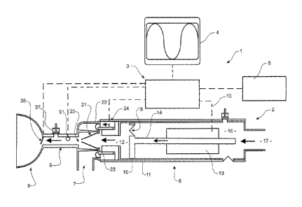
With reference to Figure 1, there is shown a resuscitator 1. The resuscitator
1
consists of a resuscitator body 2. It may also include associated hardware
such as a
controller 3, a display 4 and power supply 5 connected to each other and/or
the
resuscitator body 2.
The resuscitator body 2 consists of a pump unit 6, a flow control unit 7 and a
.. patient interface R.
CA 2688555 2017-12-13
CA 02688555 2009-11-26
WO 2008/147229
PCT/NZ2008/000128
- 12 -
-Broadly speaking the pump unit 6 includes a pump that will deliver air to the
flow control unit 7. The flow control unit 7 will control the flow of gas
between the
patient interface and the flow control unit 7 in conjunction with or without
the
pump unit 6 depending on the status of operation of the resuscitator 1.
In the most preferred form the pump unit 6 and flow control unit 7 are part of
the same body as for example shown in Figure 1. A conduit 9 extending between
the flow control unit 7 and the patient interface 8 facilitates the flow of
gas between
the interface and the flow control unit 7.
In the examples shown in the accompanying drawings, the interface is
preferably a face mask. However, alternatively, the interface may be an
endotracheal
tube or naso-tube that extends partly into the patient's airway.
The pump unit 6 consists of a piston 10 that locates in a cylinder 11 to
displace gas through an outlet 12 of the cylinder and to the flow control unit
7. The
piston and cylinder are a complementary shape and make sure that a
sufficiently
tight seal exists between the piston and cylinder for the purposes of
positively
displacing gas through the outlet 12.
The cylinder 11 may be cylindrical in cross-section or may be any other shape
in cross-section.
The piston is actuated via its connection rod 14, by a motor 13. In the most
preferred form the motor is an actuator preferably a linear motor. In an
alternative
form the actuator may be a servomotor, stepper motor or similar device. The
connection rod 14 may be the reactor to operate in conjunction with the motor
13
for the purposes of displacing the piston 10 in the cylinder 11 in an
oscillating
manner. Alternatively the connection rod 14 may carry a reactor plate or
surface in
conjunction with the motor 13. In the figures, the connection rod 14 is acted
upon
directly by the motor 13. The reactor plate may also be incorporated as part
of the
piston to be integral therewith. No connection rod may then be provided.
Alternative mechanisms may be employed where such action is indirect via a
linkage
mechanism. Such linkage may include a rotor and crank and connection rod.
In the most preferred form the motor 13 is a linear motor or any other motor
that has accurate and rapid positional control capabilities. The controller 3
via a
CA 02688555 2009-11-26
WO 2008/147229
PCT/NZ2008/000128
- 13
connection 15 with the motor 13 will operate the motor in a manner so that the
desired flow rate, volume and pressures are being delivered through the outlet
opening 12.
The flow control unit 7 consists of an inlet that may coincide with or define
the outlet 12 of the pump unit. The flow control unit includes an outlet 20
and a
passage extending between the inlet and outlet. The passage allows the
transmission
of gas being displaced from the pump unit 6 to the outlet 20. The outlet 20,
preferably via a conduit 9, allows the delivery of this gas to the patient
interface 8.
Intermediate of the inlet and outlet of the flow control unit is a one-way
valve
21. The one-way valve allows for gas to travel from the inlet towards the
outlet via
the passage but prevents flow of gas from the outlet to the inlet.
The valve 21 may be mounted in a fixed manner to the housing 22 of the flow
control unit 7 or alternatively and as shown in Figure 1, may be mounted to a
movable mount 23 to move the valve mount.
In the preferred form the movable mount 23 forms part of a voice coil
actuator 24 that can displace the movable mount 23 between two positions. The
first position is as shown in Figure 1 and the second position is as shown in
Figure
2. This creates a valve referred to herein as the exhalation or exhaust valve.
In
Figure 1 the moveable mount 23 is located in a position so that at least on
the outlet
20 side of the valve 21, no other opening to the passage of the flow control
unit 7 is
created. All gas that is displaced by the pump unit 6 is captured for flow
towards
the patient interface 8.
In the second position of the mount as shown in Figure 2, an opening 27 is
created between part of the housing 22 of the flow control unit 7 and the
moveable
mount 23. In this position gas can escape from that part of the passage of the
flow
control unit 7 intermediate of the valve 21 and the flow control unit outlet
20. In
this position of the moveable mount 23, gas that may be exhaled from the
patient
can travel through the opening 27 for example towards the surrounding
atmosphere
through opening 29. The opening 27 may be an annular opening that is created
between a substantially disk shaped mount portion and a circular shaped seat
30 of
= the housing 22 of the flow control unit 7.
CA 02688555 2009-11-26
WO 2008/147229
PCT/NZ2008/000128
- 14 -
As a consequence of a pressure differential between the patient side and pump
side of the one-way valve 21, the one-way valve 21 will assume a closed
position as
shown in Figure 2 during the exhalation operating phase of the resuscitator.
This
negative pressure differential may be established by one or more of a
combination
of the patient breathing out, the retraction of the piston in its cylinder
away from
the outlet 12 and the movement of the voice coil actuator 24 in a direction
establishing the opening 27. In the most preferred form it is the voice coil
actuator
24 that primarily establishes the open and closed condition between the
opening 27
and that part of the passage of the flow control unit 7 between the flow
control unit
outlet 20 and the one-way valve 21. However where a patient is breathing on
their
own and is able to create sufficient pressure, movement of the moveable mount
23
of the valve 21 to create the opening 27 may occur without assistance of the
voice
coil actuator. It will be appreciated that other actuators may be used.
Actuators
that move other components other than the valve 21 to create such an opening
for
exhaled gases to be discharged may be used.
In the exhalation operating phase of the resuscitator, the piston is withdrawn
by the motor 13 preferably back to a predetermined start position. The piston
retracts once it has travelled its full desired stroke during the inhalation
operating
phase and has delivered the required tidal volume or has timed out while
holding
the maximum airway pressure during the inhalation period. Control of the
position
or movement of the voice coil actuator 24 can occur by the controller 3 and is
preferably synchronised with movement of the piston.
In a "PEEP" mode (positive end expiratory pressure) parameters can be
preset by using the controller or the display panel PEEP so that pressure is
controlled by the voice coil actuator. The voice coil actuator 24 will exert a
closing
force to the exhalation valve equal to the predetermined PEEP pressure. The
PEEP pressure is measured by the airway pressure sensor 31. The controller 3
will
activate the voice coil actuator 24 when the expiratory airway pressure has
reached
the predetermined level.
In operation of the resuscitator shown in Figures 1 and 2, the tidal volume
delivered to the patient can be preset by the controller 3 or the display
panel 4. The
CA 02688555 2009-11-26
WO 2008/147229 PCT/NZ2008/000128
- 15 -
tidal volume is controlled by the stroke length of the piston 10. Tidal volume
is
delivered to the patient on the compression stroke of the piston 10 and
exhalation
for the patient is facilitated during the retraction stroke of the piston 10.
Accordingly one inhale and exhale of the patient occurs during a movement of
the
piston 10 from one starting point to its opposite end travel and back to the
starting
point. For a given cylinder size, the longer the stroke of the piston, the
greater the
tidal volume.
The controller 3 instructs the motor 13 to move the piston 10 a predetermined
= distance at a predetermined velocity.
Feedback from the airway pressure sensor 31 and a flow and tidal volume
sensor 36 can provide further control. These sensors may vary normal operation
of
the piston 10 and/or voice coil actuator 24 from conditions of operation
predetermined by an operator and instructed to the device via the display
panel 4
and/or controller 3. The stroke length and position of the piston 10 may in
addition be monitored by a sensor (a piston position sensor) of or associated
with
the motor 13 and/or piston 10. The operation of the resuscitator will control
the
breath rate and inhalation/exhalation ratio. This can be preset by using the
controller and/or display panel and may be controlled at least in part by a
timer of
the controller. Patient dependent parameters may also control operation. For
example, input information into the controller 3 may include a patient's
weight and
age.
In a situation where the airway pressure sensor 31 senses that the maximum
predetermined airway pressure has been reached, the controller 3 can instruct
the
motor 13 to slow or stop. This can result in a maintaining of the maximum
predetermined airway pressure for the duration of the inhalation time period.
In the
event of an overpressure or system failure, a safety valve 37 may be actuated
to
open and relieve pressure on the patient airway. The safety valve 37 may be a
passive valve that has predetermined operating conditions. Alternatively it
may be a
safety valve connected with the controller 3 and controlled by the controller
for
operation. Alternative to the safety valve 37, the airway pressure sensor 31
and/or
flow and tidal volume sensor 36 may communicate with the controller 3 to
direct
CA 02688555 2009-11-26
WO 2008/147229 PCT/NZ2008/000128
- 16 -
movement of the voice coil actuator in instances where undesirable conditions
are
being sensed to thereby relieve pressure and/or flow by exhausting gas through
the
opening 29.
This first form of resuscitator described as well as the form yet to be
described
allows for data from the airway pressure sensor 31, the piston position
sensor, the
flow and tidal volume sensor 36 and from a timer to be used to record
operating
data and performance. A graphical display on the display panel 4 can also be
generated. The graphical display can be used by the operator to monitor
performance and determine if leakage, blockage or further adjustments are
requited
to the resuscitator. The graph and/or related data can be stored to assist in
the
setup of other life support systems and for clinical analysis. Such
statistical
, information may offer significant benefits to future situations.
The electrical connection 15 will ensure that the controller 3 can
appropriately =
control the linear motor to thereby control the position and movement of the
piston. The cylinder 11 has an inlet volute 16 that includes a primary inlet
17. It is
through the primary inlet that ambient air may be drawing into the inlet
volute as
the piston displaces inside the cylinder towards the outlet 12. This direction
of
travel is shown in Figure 1. The piston 10 carries a one-way valve 18 that
operates
to be in a closed condition when the piston is travelling towards the outlet
12. This
will result in a drawing of ambient air into the inlet volute 16. When the
piston 10
travels in the opposite direction being an exhalation direction of the
resuscitator, the
one-way valve 18 can open to allow for air in the inlet volute 16 to displace
into the
region between the piston 10 and the outlet 12 as for example shown in Figure
2.
The primary inlet 17 may include a one-way valve to assist such displacement
through the opening created by the one-way valve through the piston by
preventing
air in the inlet volute 16 from displacing back out through the primary inlet
17. The
gas that has displaced into the space between the piston 10 and the outlet
opening
12 can then on the return stroke during the inhalation phase of operation be
displaced at least in part through the outlet opening 12 and to the flow
control unit
7.
CA 02688555 2009-11-26
WO 2008/147229
PCT/NZ2008/000128
- 17 -
The resuscitator may (for example shown in Figure 3) operate in a
supplementary oxygen and C-pap mode. A supplementary oxygen reservoir 40 (that
may or may not be connected to supplementary supply via the inlet 41) can be
engaged to the primary inlet 17 of the pump unit 6. Rather than drawing
ambient
air into the pump unit, the oxygen or other gas or gas mixture can be supplied
to a
patient via the resuscitator. This will allow the operator to control -the
delivery of an
"air/oxygen mixture by the use of for example an external blender.
Supplementary
gas such as oxygen may be delivered via the primary inlet 17 to the pump unit,
under pressure. In the event of a failure or the gas supply exceeding the
capabilities
of the resuscitator, then a safety valve 42 may open to exhaust gas from at
least part
of the pump unit 6. A pressure sensor may be located in an appropriate
location for
these purposes. If a failure occurs with the supplementary gas supply or the
primary
inlet 17 becomes blocked then a safety valve 43 may open to allow for ambient
air
to be drawn into the pump unit 6 allowing ongoing operation of the
resuscitator
despite issues with the supply of supplementary gas.
In a C-pap mode operational conditions can be specified and preset by using
the controller and/or display panel. Where the delivery rate and pressure to
the
supplementary gas reservoir 40 is set at an appropriate flow level, the
ventilator can
operate in the C-pap mode. The motor 13 will stop operation and the flow from
= 20 the supplementary oxygen reservoir 40 will pass through the one-way
valve 18
through the one-way valve 21 to the patient interface 8. The airway pressure
sensor
31 will determine the patient's airway pressure. When the predetermined C-pap
pressure has been reached the voice coil actuator 24 will exert a closing
force to the
exhalation valve to the predetermined C-pap pressure.
With reference to Figure 4 there is shown a variation to the resuscitator
described with reference to Figures 1-3 wherein a flexible conduit 56 is
provided to
extend between the pump unit 6 and the flow control unit 7. The flexible
conduit
56 may be fitted between the pump unit and the flow control unit to allow for
delivery for gas displaced by the piston 10 towards the patient interface 8.
Having
the flow control unit 7 and airway pressure sensors and tidal volume sensors
as well
as the safety valve 37 close to the patient's airway, ensures a more accurate
tidal
CA 02688555 2009-11-26
WO 2008/147229
PCT/NZ2008/000128
- 18 -
volume and pressure delivery. Also the controller can make adjustments for the
compliance in the patient mask. Also possible but less advantageous is to
provide a
conduit 9 that is of a desired length to allow for more distal location
between the
patient interface 8 and the pump unit 6. However this has the disadvantage of
dead
space between the features of the flow control unit 7 and the patient
interface 8.
The resuscitator of Figures 1-4, wherein the piston is single acting, lends
itself
particularly to resuscitation and ventilation of neonatal patients. A
manageable sized
pump unit can be provided wherein in one stroke of the piston a sufficient
tidal
volume of air can be delivered to a neonatal patient for inhalation. It is
desirable for
the unit to be relatively portable and therefore size can be a design
constraint.
However where size is not an issue, the pump unit 6 can be scaled up so that
single
compression stroke- of the piston can deliver a sufficient tidal volume of gas
to
larger patients. However this will increase at least the size of the pump unit
6
making it less convenient for portability purposes.
An alternative configuration of resuscitator may be utilised where size can be
smaller. This resuscitator is shown for example in Figure 5. The resuscitator
101
includes a patient interface 108, flow control unit 107 and related components
that
are preferably the same as those described with reference to the resuscitator
of
Figures 1-4.
This alternative form of resuscitator also includes a pump unit 106. The pump
unit 106 varies to the pump unit 6 described with reference to Figures 1-4.
There is
provided a motor 113 such as a linear motor or servo motor controlled by a
controller 103 that may be engaged with a display panel 104. The linear motor
operates a piston 110 via a connection such as a connection rod 114 that
operates in
a cylinder 111. The pump unit 106 includes an inlet volute 116. The inlet
volute via
a primary inlet 117 can draw air or supplementary gas supply therethrough as a
result of the action of the piston and into the inlet volute 116.
The cylinder includes two openings capable of being in communication with
the inlet volute 116. A first opening 160 is provided on the extension side of
the
piston 110. A second opening 161 is provided on the retraction side of the
piston
110. The opening 160 is closable by a one-way valve 162. The opening 161 is
CA 02688555 2009-11-26
WO 2008/147229
PCT/NZ2008/000128
- 19 -
closable by a one-way valve 163. The one-way valve 162 is able to assume an
opening condition during the retraction stroke of the piston and is in a
closed
condition during the extension stroke of the piston. The one-way valve 163 is
able
to assume an open position during the extension stroke of the piston and is in
a
closed condition when the piston is retracting. = On the extension side of the
piston
110 is an outlet opening 164 of the cylinder 111. The outlet opening is
closable by a
one-way valve 165. The one-way valve 165 is in a closed condition during the
retraction stroke of the piston and is able to assume an open condition during
the
extension stroke of the piston. The one-way valve 165 hence essentially works
in an
opposite mode to the one-way valve 162 to the cylinder. The outlet opening 164
is
able to create a fluid connection of that part of the cylinder on the
compression side
of the piston with an outlet volute 166. The outlet volute 166 includes an
outlet
opening 112 through which gas displaced by the piston can pass to the flow
control
unit 7. The outlet volute 166 is separated from the inlet volute 116. The
housing of
the pump unit 106 may include both the inlet volute 116 and outlet volute 166
and
partitions 167 and the cylinder 111 may separate the volutes. On the
retraction side
of the piston 110 the cylinder includes an opening 168 to the outlet volute
166. The
opening 168 includes a one-way valve 169. The one-way valve is positioned so
that
during the retraction stroke of the piston, gas can displace on the retraction
side of
the cylinder through the one-way valve 169 into the outlet volute 166. The one-
way
valve 169 will assume a closed condition during the extension stroke of the
piston
110.
In operation during the extension stroke of the piston as shown in Figure 6,
the one way valve 163 opens allowing for air to be drawn into the retraction
side of
the cylinder. Air on the extension side of the piston during the extension
stroke can
be displaced through the one-way valve 165 to be delivered into the outlet
volute.
One-way valve 169 will be closed thereby only offering one outlet to the
outlet
volute 166 being the outlet 112. During the extension stroke of the piston the
retraction side of the cylinder is charged with gas being drawn through the
one-way
valve 163. When the piston travels in its retraction stroke as shown in Figure
7, gas
that has been drawn into the retraction side of the cylinder may then be
displaced
CA 02688555 2009-11-26
WO 2008/147229
PCT/NZ2008/000128
- 20 -
through the one-way valve 169 into the outlet volute 166. The one-way valve
163
will close during the retraction stroke thereby creating only one outlet from
the
cylinder on its retraction side, namely the opening to discharge the gas into
the
outlet -volute 166. During the retraction stroke the one-way valve 165 is
closed
thereby offering only one outlet for gas being delivered into the outlet
volute,.
namely being the outlet opening 112. .During the retraction stroke the
extension
side of the cylinder is charged with gas from the inlet volute 116 via the one-
way
valve 162 that is in that condition opened. As can be seen the pump unit 106
hence
operates in a double acting manner. Both during the extension and retraction
stroke
of the piston gas is displaced towards the opening 112 for delivery towards
the
patient. With the use of a linear motor or servo motor having high frequency
capabilities and accurate and immediate start and stop timing, a high
frequency
operating piston can deliver gas to the patient in effectively a continuous
manner
during both the retraction and extension strokes. Each tidal volume delivered
to the
patient may involve a high number of strokes of the piston. This allows for a
compact and preferably portable unit to be provided. Upon exhalation of the
patient the flow control unit 107 may be operated to open the exhaust valve to
allow for exhalation to occur may coincide with the linear motor stopping
operation. Alternatively the linear motor may continue oscillating the piston
but
where a waste valve may be opened to discharge displaced air from the piston
from
reaching the flow control valve. Alternatively such wasting may occur via the
exhaust valve of the flow control.
With reference to Figure 8 the resuscitator described with reference to
Figures
5-7 is also capable of operating in a supplementary gas and/or C-pap mode.
This is
shown for example in Figure 8. Furthermore an extension conduit 156 may be
utilised as shown in Figure 9.
The number of oscillations that the piston may run through can be
predetermined. The oscillations determine the tidal volume that is delivered
to the
patient. An operator may interact with the control unit and/or display to set
parameters of operation of the resuscitator. Like the resuscitator described
with
reference to Figures 1-4 stroke length and position of the piston as well as
airway
CA 02688555 2009-11-26
WO 2008/147229
PCT/NZ2008/000128
- 21 -
pressures and tidal volume flow and volume sensing may occur and be recorded
and
displayed.
The airway pressure may be monitored by a pressure sensor. When the
pressure sensor senses that the maximum predetermined airway pressure has been
reached the controller then instructs the linear motor to stop or slow to
maintain
the maximum predetermined airway pressure for the duration of the inhalation
period. Alternatively the controller may instruct the linear motor to stop to
reduce
pressure. In the event of any over pressure or system failure a safety valve
like that
described with reference to Figures 1-4 may open.
The voice coil actuator may be preloaded so that the exhaust port tends to an
open biased condition allowing external air to enter the patient airway.
The resuscitator of Figures 5-9 rnay also operate in a PEEP mode as
previously described. In the C-pap mode of operation all one-way valves to the
cylinder are opened. This allows for direct transfer of gas from the inlet
volute 116
to the outlet volute 166 and to the patient. Pressure sensors and relief
valves may
be included for failsafe purposes.
With reference to the resuscitators in Figures 1-9, parts of the resuscitator
may
be disposable. In particular those parts of the resuscitator that have been
exposed
to exhaled breath or air from a patient may be disposable. They may be
manufactured and assembled in a way to facilitate their disposable use. For
example
the patient interface 8, the flow control unit 7 and one way valve 21 and/or
the
voice coil actuator 24, movable mouth 23 and housing 22 may all be
disengageable
from the pump unit 6 and be disposed after use. Circuits to allow for a quick
connection of the controller 3 to a replacement assembly of such parts may be
provided through simple plug/socket arrangement(s). A single plug/socket may
be
provided. This may automatically become coupled upon the engagement of the
disposable components with the pump unit 6.
With reference to Figures 10 and 11 there is shown more detail in respect of
the tidal volume and flow sensor. In Figure 10 there is shown the patient
interface
208 wherein the flow and tidal volume sensor 236 is shown during the
inhalation
phase of operation. It is connected to the controller 203 via a connection
283.
CA 02688555 2009-11-26
WO 2008/147229
PCT/NZ2008/000128
- 22 -
With reference to Figure 11, the sensor 236 is shown in the exhalation phase.
The
sensor 236 is of a kind that displaces dependent on aft flow past it. Such may
not
be ideal for accurate sensing due to inertial mass of the sensor.
An alternative form of a sensor is one that has no inertial mass delay
characteristics. An alternative form of sensor that may be used may be a gas
flow
meter that measure flow thermally. An example of such a flow meter is one
manufactured by Sensirion.com such as their digital gas flow sensor
ASF1400/ASF/1430. It may be one that is made in accordance to that described
in
US6813944. Such a flow sensor has a high response rate, given that it has
unlike the
sensor of Figure 10, it has no mass to be displaced by the flow. A fast
response can
be beneficial. Such sensors may commonly be referred to as a hot wire flow
sensor
or thermal mass flow meters. The sensor or an alternative sensor may also
measure
the temperature of the exhaled breath. With an appropriate sensor where the
response rate is very quick (a matter of, for example one tenths of a second)
it is
possible during the exhale of a patient to measure the patient's core
temperature.
This information may also be collected and/or displayed or otherwise used by
the
resuscitator.
The invention may offer the advantages of being portable, hand held
(including being able to be held by one hand in order to hold the patient
interface in
the appropriate condition) and self contained by virtue of including its own
power
source (such as a 12 v power supply).
The device may have programmable profiles fixed and/or customised to suit
patients, clinicians and operators requirements.
A heart rate monitoring facility may also be incorporated with the device,
wherein heart rate can be accounted for in the control of the device and be
displayed by the device.
The display can assist the operator in evaluating resuscitation of the
patient.
The performance, operating parameters and status of the features of the device
are
able to be recorded. This can assist in statistical analysis and to gather
information
for set-up of other devices.
The patient as herein defined may a mammal such a person or animal.