Note: Descriptions are shown in the official language in which they were submitted.
CA 02690605 2009-12-11
WO 2008/154631 PCT/US2008/066709
DISPLAY PACKAGE ASSEMBLY
FIELD OF THE INVENTION
Generally speaking, the present invention relates to packages comprising an
inner
support structure and a surrounding outer sleeve. More specifically, the
present invention
relates to packages wherein the items stored within an interior cavity are
accessible by
removing an outer sleeve or a portion thereof, such as a front panel or end
cap.
BACKGROUND
The present invention departs from the current packaging industry environments
and the known prior art through the creative manner in which the inventors
identified
present and future needs, and then developed flexible solutions that address
both isolated
and overlapping failures in the present art to satisfy those needs. Through
the present
invention, as taught and illustrated through exemplary embodiments, obstacles
including
structural integrity, display, privacy, child-resistance, tamper evidence,
ease of access,
consistent operation through repeated use, and price-point economics are
simultaneously
solved.
BRIEF DESCRIPTION OF THE DRAWINGS
FIG. I illustrates an exemplary blank for forming an embodiment of a primary
container, according to the present invention.
FIG. 2 illustrates an exemplary blank for forming an embodiment of an outer
sleeve, according to the present invention.
1
SUBSTITUTE SHEET (RULE 26)
CA 02690605 2009-12-11
WO 2008/154631 PCT/US2008/066709
FIG. 3 is a perspective view of an exemplary primary container, according to
the
present invention.
FIGs. 4a-4c are perspective views of an exemplary package and a method of use,
according to the present invention.
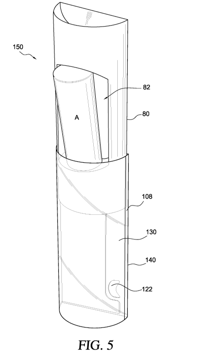
FIG. 5 is a perspective view of an exemplary package, according to the present
invention.
FIG. 6 illustrates an exemplary alternative blank, according to the present
invention.
FIG. 7 is a perspective view of the partially erected blank of FIG. 6,
according to
the present invention,
FIG. 8 is a perspective view of a partially erected container, according to
the
present invention.
FIGs. 9a - 9b are perspective views of an exemplary container and a method of
use, according to the present invention.
FIG. 10 illustrates exemplary blanks for forming an embodiment of a primary
container, according to the present invention,
FIG. 11 illustrates an exemplary blank for forming an embodiment of an outer
sleeve, according to the present invention.
FIG. 12 is a perspective view of an embodiment of an exemplary package,
according to the present invention.
FIG. 13 is an alternative perspective view of an embodiment of an exemplary
package, according to the present invention.
2
SUBSTITUTE SHEET (RULE 26)
CA 02690605 2009-12-11
WO 2008/154631 PCT/US2008/066709
DETAILED DESCRIPTION
As required, detailed embodiments of the present invention are disclosed
herein.
It must be understood that the disclosed embodiments are merely exemplary
examples of
the invention that may be embodied in various and alternative forms, and
combinations
thereof. As used herein, the word "exemplary" is used expansively to refer to
embodiments that serve as an illustration, specimen, model or pattern. The
figures are
not necessarily to scale and some features may be exaggerated or minimized to
show
details of particular components. In other instances, well-known components,
systems,
materials or methods have not been described in detail in order to avoid
obscuring the
present invention. Therefore, specific structural and functional details
disclosed herein
are not to be interpreted as limiting, but merely as a basis for the claims
and as a
representative basis for teaching one skilled in the art to variously employ
the present
invention.
Referring now to FIG. 1, wherein like numerals refer to like elements
throughout
the various figures, there is shown a primary blank 10 comprising a plurality
of foldably
attached panels, namely, a tray rear panel 12, a tray center panel 14, a back
panel 16, a
tray top panel 18, and a glue flap 20. These panels 12, 14, 16, 18, 20 are
foldably
attached along fold lines 24, 26, 28, 30, respectively.
The illustrated tray center panel 14 further includes end wall flaps 40,
foldably
attached along fold lines 42, and tray end wall flaps 44. The tray end wall
flaps 44 are
defined by fold lines 46 and cut lines 48, the cut lines further defining a
removed section
50. The illustrated end wall flaps 44 further include securing apertures 52
for receiving
and holding an item (A), as described below. Alternative embodiments present
3
SUBSTITUTE SHEET (RULE 26)
CA 02690605 2009-12-11
WO 2008/154631 PCT/US2008/066709
alternative means for securing that hold an item. End flaps 54 are foldably
attached to
the back panel 16 along fold lines 56. The illustrated tray top panel 18
includes tray side
wall flaps 60, foldably attached along fold lines 62. The side wall flaps 60
are further
defined by cut lines 64, which also define another removed section 66. The
illustrated
glue flap 20 also includes a stop tab 70, foldably attached atong a fold line
72 and
defined, in part, by opposite cut lines 74. When erected, this exemplary
primary blank 10
forms a primary container 80 that defines an internal cavity 82, as best
illustrated and
described with references to FIGs 3 - 5.
Turning to FIG. 2, there is shown a secondary blank 100 having of a plurality
of
foldably attached panels. Here an inner panel 102, a side panel 104, a front
panel 106,
another side panel 108, and an inner panel 110 are foldably connected along
fold lines
112, 114, 116, 118, respectively. The illustrated inner panel 102 includes a
stop tab
receiving channel cutout 120 and the illustrated back pane1110 includes a stop
tab
keyhole 122. When erected this exemplary secondary blank 100 forms an outer
sleeve or
exterior container 140, which includes a receiving channel 130, configured to
slideably
receive the primary container 80 and stop tab 70, as best illustrated and
described with
reference to FIGs. 4a-4c and 5.
Before turning fully to FIGs. 4a-4c and 5, where the function and operation of
an
exemplary package 150 is taught, we refer concurrently to FIGs 1-3 to teach
how the
illustrated blanks 10, 100 are folded and erected to form the primary
container 80 and
outer sleeve 140. One non-limiting method of erecting the illustrated primary
blank 10
includes folding the tray rear panel 12 upwardly and inwardly along its
adjacent fold line
24 toward the tray back pane116. While folding the tray rear pane112 the tray
center
4
SUBSTITUTE SHEET (RULE 26)
CA 02690605 2009-12-11
WO 2008/154631 PCT/US2008/066709
panel 14 will follow, rotating about a second adjacent fold line 26. Before or
after
placing the back of the tray rear panel 12 over the face of the back panel 16
to form a tray
base, the tray end wall flaps 44 are folded downwardly along adjacent fold
lines 46 into
positions that are substantially perpendicular, with respect to the rear
pane112, and
opposite each other. Further, the end wall flaps 40 are pressed inwardly along
adjacent
fold lines 42 to form end walls that are curved and substantially
perpendicular with
respect to the rear panel 12. Thereafter, each end flap 54 is folded
completely inwardly
along its adjacent fold line 56 to lock the ends of the tray rear panel 12. In
this
configuration, an internal cavity 82, in this case a tray for receiving and
holding an item
(A), is partially erected. Completing this method of erecting, the glue flap
20 is folded
upwardly and inwardly along its adjacent fold line 30 toward and around the
erected tray
center panel 14, and then the face of the glue flap 20 is attached to the
exposed back of
the back pane116. While folding the glue pane120 the tray top panel 18 will
follow,
rotating about a second adjacent fold line 28. Before or after attaching the
glue flap 20 to
the back panel 16, the tray side wall flaps 60 are folded downwardly along
adjacent fold
lines 62 into positions that are opposite each other and substantially
perpendicular, with
respect to the rear panel 12. FIG. 3 illustrates an erected and standing
primary container
80.
In alternative embodiments the tray rear panel 12 is attached to the tray
center
panel 16, thus eliminating the end flaps 54. Further, alternative internal
cavity 82
configurations are contemplated as provided by tray center panels 14 and/or
tray top
panels 18 of alternative designs. In addition, alternative embodiments vary
the width and
size of certain panels, reposition certain panels or tabs, reconfigure certain
panels or tabs,
5
SUBSTITUTE SHEET (RULE 26)
CA 02690605 2009-12-11
WO 2008/154631 PCT/US2008/066709
and eliminate certain panels and tabs. For example, alternative embodiments
can reduce
or eliminate the tray rear panel 12, reduce or eliminate the glue flap 20,
reduce or
eliminate the tray side wall flaps 60, reduce or locate the stop tab 70 to the
back panel 16,
and reconfigure the tray end wall or side wall flaps 44, 60.
Referring now to FIGs. 2, 4 and 5, one non-limiting method of erecting the
secondary blank 100 includes inwardly folding the inner panel 102 along an
adjacent fold
line 112 and then inwardly folding the exterior back panel 110 along an
adjacent fold line
118 so that the inner panel 102 and back panel 110 are in a face-contacting
configuration.
The back of the back panel 110 is then attached to the face of the inner panel
102. In
connecting the back panel 110 and inner panel 102, the stop tab receiving
channel cutout
120 cooperatively forms a receiving channel 130, and the sidewall panels 104,
108 are
substantially perpendicular, with reference to the back panel 110. When fully
erected the
blanks 10, 100 result in the primary container 80 and outer sleeve 140 that
comprise a
package 150, best illustrated in FIG. 5.
With regard to FIGs. 4 and 5, the exemplary package 150 is created by
inserting
an erected primary container 80 into an erected outer sleeve 140. For clarity
and
purposes of teaching, and not as a limitation or restriction, the exemplary
package 150 is
illustrated with a transparent outer sleeve 140 and opaque primary container
80. In the
fully closed position shown in FIG. 4a the item(s) stored in the internal
cavity 82 may be
visible but are not easily accessible. For those embodiments where the stop
tab 12 is
absent or not restrained, the primary container 80 can be slid by pushing on
either end
wall structure until it is slid out from the outer sleeve 140 enough to access
the items
stored in the internal cavity 82. For those embodiments that include a stop
tab 70 and
6
SUBSTITUTE SHEET (RULE 26)
CA 02690605 2009-12-11
WO 2008/154631 PCT/US2008/066709
elongated receiving channel 130, the primary container 80 is stopped from
further sliding
when the stop tab 70 abuts an end of the receiving channe1130, as best shown
in FIG. 4c.
Consideration is now given to those embodiments that include a child-
resistance
feature comprising a stop tab 70 and stop tab keyhole 122, as best shown in
FIGs. 4a - 4c
and 5. As shown in FIG. 4a, the exemplary package 150 is locked because the
stop tab
70 extends outwardly beyond the plane of the stop tab keyhole 122. To unlock
the
package 150 the stop tab 70 is completely pushed through the stop tab keyhole
122 and
seated within the receiving channel 130. With the stop tab 70 fully seated
within the
receiving channel 130 the primary container 80 can be partially or fully
extended within
the outer sleeve 140, as best shown in FIGs. 4 and 5. This setting of the stop
tab 70
requires a certain level of cognitive development and coordination that is
beyond some
age groups. Accordingly, even a vigorous attempt by an unintended user to
slide the
primary container 80 before seating the stop tab 70 should be thwarted if the
respective
blanks 10, 100 are of sufficiently sturdy materials.
Where a vigorous attempt is not thwarted and one or more components of the
package are destroyed - most likely the stop tab 70, the destroyed
component(s) serves as
tamper evidence. In some embodiments the stop tab 70 is secured to one or more
outer
sleeve panels 106, 108, 110. By way of example and not limitation, the stop
tab 70 may
be folded back and attached to the front panel 106 or sidewall 108 with
adhesives or
glues, or sealed with tape. Alternatively, the stop tab 70 can be similarly
attached to the
back panel 110. An unsecured or unsealed stop tab 70 serves as further tamper
evidence.
It is contemplated that some package embodiments will include a child-
resistant
feature that includes a stop tab 70, such as those packages that store and
dispense
7
SUBSTITUTE SHEET (RULE 26)
CA 02690605 2009-12-11
WO 2008/154631 PCT/US2008/066709
prescription drugs that could be harmful if ingested by a small child. Where
the end-user
does not require a child-resistant feature because there are no children in
his or her
environment, the stop tab 70 can be permanently removed by severing it from
the
attached pane120.
Referring now to FIG. 6, there is shown an alternative composite blank 200
comprising a plurality of foldably attached panels, namely, a tray rear panel
12, a tray
center pane114, a back panel 16, a tray top panel 18, and a glue flap 20.
These panels 12,
14, 16, 18, 20 are foldably attached along fold lines 24, 26, 28, 30,
respectively.
The illustrated tray center panel 14 further includes end wall flaps 40,
foldably
attached along fold lines 42, and tray end wall flaps 44. The tray end wall
flaps 44 are
defined by fold lines 46 and cut lines 48, the cut lines 48 further define a
removed section
50. The illustrated end wall flaps 44 further include securing apertures 52
for receiving
and holding an item (A), as described below. End flaps 54 are foldably
attached to the
back panel 16 along fold lines 56. The illustrated back panel 16 includes a
stop tab
keyhole 122. The illustrated tray top panel 18 includes a window 202 overlaid
by a
window pane 204. The illustrated glue flap 20 also includes a stop tab 70,
foldably
attached along opposite fold lines 72 and defined, in part, by a cut line 74
that defines a
locking edge 206. When erected, this exemplary composite blank 200 forms a
composite
container 220 that includes an internal cavity 210 and locking sleeve 212, as
best
illustrated and described with references to FIGs. 7 - 9a-9b.
As illustrated by FIG. 7, the folding and erecting of the composite blank 200
tray
rear panel 12, tray center panel 14, and back panel 16 are substantially the
same as
described above with reference to the primary blank 10. After the internal
cavity 210 is
8
SUBSTITUTE SHEET (RULE 26)
CA 02690605 2009-12-11
WO 2008/154631 PCT/US2008/066709
formed, as best shown in FIGs. 7 and 8, an item(s) (A) can be inserted and
held by the
end wall flaps 44, or similar means for securing. Completing this method of
erecting, the
glue flap 20 is folded upwardly and inwardly along its adjacent fold line 30
toward and
around the erected tray center panel 14, and then the locking edge 206 of the
stop tab 70
is inserted into the stop tab keyhole 122 located on the back panel 16. While
folding the
glue panel 20 the tray top panel 18 will follow, rotating about a second
adjacent fold line
28. As the stop tab 70 is attached to the back pane116, the top panel 18
covers the
internal cavity 210 and any item(s) (A) therein. In the illustrated embodiment
the
window pane 204 provides a view to the internal cavity 210 and any contents.
In
alternative embodiments, there is no window 202 or window pane 204.
As best illustrated by FIGs. 7 and 8, the composite blank 200 combines many
elements found in the primary blank 10 and secondary blank 100 to provide a
composite
container 220 that combines many of the features of the primary container 80
and outer
sleeve 140.
Consideration is now given to those embodiments that include a child-
resistance
feature comprising a stop tab 70 and stop tab keyhole 122, best shown in FIGs.
9a, 9b. In
a locked configuration the stop tab locking edge 206 is inserted into the stop
tab keyhole
122. As best shown in FIG. 9a, the exemplary package 220 is unlocked by
lifting the
locking tab 70 upwardly and outwardly, which pulls the locking edge 206 from
the stop
tab keyhole 122. By continuing to lift the glue flap 20 away from the back
panel 16 and
rotate the glue flap 20 about the container, as shown by the directional
arrows in FIGs.
9a, 9b, the top panel 18 is pulled away to reveal the contents of the internal
cavity and to
allow access to the content.
9
SUBSTITUTE SHEET (RULE 26)
CA 02690605 2009-12-11
WO 2008/154631 PCT/US2008/066709
In some embodiments, the stop tab 70 is secured to one or more outer sleeve
panels 16, 18. By way of example and not limitation, the stop tab 70 may be
attached to
the back pane116 or front pane118 with adhesives or glues, or sealed with
tape. An
unsecured or unsealed stop tab 70 serves as further tamper evidence.
Turning now to FIG. 10, there is shown a pair of alternative primary blanks
300,
302 that cooperate to form a primary container 306 and internal cavity 308,
described
below.
The first primary blank 300 combines a plurality of some panels described
above,
namely, a tray top panel 18, a tray center pane114, a back panel 16, and a
glue flap 20.
These panels are foldably attached along fold lines 24, 26, 28, respectively.
The tray top
panel 18 and tray center panel 14 include end wall flaps 40 foldably attached
along fold
lines 42, a tray end wall flap 44 foldably attached along a fold line 46, and
an end flap 5 6
foldably attached along a fold line 56. The tray end wall flap 44 further
includes securing
apertures 52. In addition, these panels 18, 14 each include a locking tab
aperture 304. To
erect the first primary blank 300 the glue flap 20 is folded upwardly and
inwardly so that
the back of the glue flap 20 is laid over and attached to the tray center
panel 14. In this
configuration the back panel 16 faces the glue flap 20 and extends upwardly
between
adjacent fold lines 26, 28. The tray top panel 18 is likewise folded upwardly
and
inwardly so that the face of the top panel 18 is laid over and attached to the
back panel
16. In this configuration a first end wall structure, having an overall
profile, begins to
take shape. To complete this assembly the end wall flaps 40 are folded
inwardly, and
then the tray end wall 44 and end flap 54 are folded inwardly and attached to
the
SUBSTITUTE SHEET (RULE 26)
CA 02690605 2009-12-11
WO 2008/154631 PCT/US2008/066709
respective end wall flaps 40. The result is a first end wall structure 310
configured to
lockably engage a first end of an outer sleeve 410.
The second primary blank 302 combines the same plurality of panels as
described
above, namely, a tray top panel 18, a tray center panel 14, a back panel 16,
and a glue
flap 20. These panels are similarly configured and include the same elements,
except that
the second blank 302 includes a stop tab keyhole 122 instead of locking tab
apertures
304. The assembly of the second end wall blank 302 is substantially identical
to the
assembly of the first end wall blank 300. The result is a second end wall
structure 320
configured to releaseably engage a second end of an outer sleeve 410.
With reference now to FIG. 11, there is shown a secondary blank 400 having a
plurality of foldably attached panels. Here a back panel 110, a front panel
106, and an
inner panel 102 are foldably connected along fold lines 112, 114,
respectively. The
illustrated back panel 110 includes a stop tab 70 defined, in part, by
opposite cut lines 72
and a fold line 74. Further, the back panel 110 and front panel 106 each
include a locking
tab 402. When erected in the manner described above with regard to the first
outer sleeve
140, and with the locking tabs 402 folded inwardly, this exemplary secondary
blank 400
forms an outer sleeve or exterior container 410 best illustrated and described
with
reference to FIGs. 12 and 13.
Referring now to FIGs. 12 and 13, there is shown an exemplary package 500,
comprising a first end wall structure 310 and a second end wall structure 320
that define a
primary container 306, and an outer sleeve 410, which, together, define an
inner cavity
308 for holding an item(s) (A). The first end wall structure 310 is locked to
the outer
sleeve 410 by inwardly folding the locking tabs 402 and inserting the end wall
structure
11
SUBSTITUTE SHEET (RULE 26)
CA 02690605 2009-12-11
WO 2008/154631 PCT/US2008/066709
310 into that end of the outer sleeve 410 until the locking tabs 402 engage
the locking tab
apertures 304. The second end wall structure 320 is releaseably locked to the
outer
sleeve 410 by inserting the end wall structure 320 into the opposite end of
the outer
sleeve, and then inserting the stop tab 70 into the stop tab keyhole 122.
To open or otherwise access the contents held by this embodiment, the stop tab
70
is removed from the stop tab keyhole 122 and then the second end wall
structure 320 can
be slideably removed from the outer sleeve 410. As described above, the stop
tab 70 may
include additional theft resistant, child-resistant, and tamper resistant
features.
While the primary blanks 10, 300, 302, the secondary blanks 100, 400, and the
combined blank 200 are illustrated and described as unitary blanks, it will be
understood
that the respective blanks can be formed of individual, separate panels that
are connected
or otherwise attached to form an erected primary container and outer sleeve
similar to
those illustrated and described below. In addition, some panels are referenced
with
directional or orientation words such as "front", "back", "interior" and
"exterior" to
merely indicate relative positions in an erected configuration; accordingly,
these terms
are merely used for ease of reference and teaching and not as a limitation or
restriction of
any kind.
The law does not require and it is economically prohibited to illustrate and
teach
every possible embodiment of the present claims. Hence, the above-described
embodiments are merely exemplary illustrations of implementations set forth
for a clear
understanding of the principles of the invention. Variations, modifications,
and
combinations may be made to the above-described embodiments without departing
from
12
SUBSTITUTE SHEET (RULE 26)
CA 02690605 2009-12-11
WO 2008/154631 PCT/US2008/066709
the scope of the claims. All such variations, modifications, and combinations
are
included herein by the scope of this disclosure and the following claims.
13
SUBSTITUTE SHEET (RULE 26)