Note: Descriptions are shown in the official language in which they were submitted.
CA 02698137 2010-03-01
WO 2008/028092 PCT/US2007/077319
AEROSOL GENERATING AND DELIVERY DEVICE
FIELD OF THE INVENTION
Particular exemplary aspects relate generally to aerosolized particle
generation and delivery
of same to a user, and more particularly to novel devices and apparatus for
atomized particle
generation, and to novel integrated particle generation, dispersion and
delivery devices suitable for
targeted delivery to a user including, but not limited to the nasal cavity or
regions thereof of a user,
the inside of the mouth of a user, the skin of the user, the surface of the
eye of a user, and the
vicinity of a user. Additional exemplary aspects relate to novel methods for
administration of
therapeutic agents to the nasal cavity, deep nasal cavity and paranasal
sinuses of a user (e.g., a
patient) using the novel devices, and to ocular and oral delivery using the
novel devices. Further
exemplary aspects relate to aerosolization and delivery of perfume, fragrance,
essential oil or
cosmeceutical agents and the like.
CROSS-REFERENCE TO RELATED APPLICATIONS
This application claims the benefit of priority to United States Provisional
Patent
Application Serial Number 60/824,017, filed 30 August 2006, which is
incorporated by reference
herein in its entirety.
BACKGROUND
In the United States, sixty million people suffer from chronic sinusitis and
allergic rhinitis
and are treated by means of topically applied antihistamines, antibiotics,
decongestants, and pain
relievers. Many of these drugs would work more effectively in relieving
symptoms if they could be
applied directly to all of the affected areas. However, the devices utilized
thus far to deliver these
drugs have proven to be extremely inadequate, if not useless, in reaching all
areas needed especially
the deep nasal cavity, olfactory region, and paranasal sinuses critical to the
treatment of some of
these diseases and conditions. In addition to topically applied drugs (e.g.,
such as particular drugs
in the categories listed above), there are a wide variety of systemically-
absorbed drugs that are
1
CA 02698137 2010-03-01
WO 2008/028092 PCT/US2007/077319
delivered intranasally. Moreover, a completely new field of nose to brain drug
delivery is
emerging. Current devices utilized for such systemically-absorbed drugs have
also proven to be
inadequate for many applications.
Current delivery systems comprise, for example, metered dose spray bottles and
pneumatic
(e.g., compressed air) atomizers that eject the medicine into the nostrils in
large particles, or streams
of atomized liquid. While a substantial mass of aerosolized particles can be
quickly ejected or
projected from such devices, the ejected or projected particles are relatively
large, such that the
efficacy of medicine administered in this manner is limited because of
variable user skill and
inadequate delivery and/or target distribution. For example, because of the
relatively large particle
sizes and the velocity vectors and characteristics of the particles, medicines
delivered in this manner
reach very little of the nasal mucosa and essentially no part of paranasal
sinuses. Instead, such
devices spray the particles into, for example, the anterior nasal cavity where
the substantial mass of
the particles impact the surfaces and drip out the nostril, or quickly clear
along the floor of the nasal
cavity. In cases of severe congestion or nasal polyps, the medicine often does
not proceed beyond
the nostril and has no chance of being effectively absorbed into the
bloodstream in the necessary
area of the nasal cavity. Therefore, while current prior art metered dose
spray bottles and
pneumatic atomization systems allow for rapid mass delivery, they are
typically of relatively crude
simplistic design, and substantially waste medicament because they do not
provide adequate
particle size distributions or delivery targeting for many purposes (e.g.,
they do not allow for
particles to penetrate or reach high into the nasal cavity, and be retained
therein, as required for
systemic nose to brain delivery, or for paranasal sinus delivery.
As an improvement, pneumatic (e.g., compressed air) nebulizers have been
developed and
are familiar in the art. Fundamentally, nebulizers are distinguished from
simple atomizers by the
presence in the former of an `impaction or stagnation baffle' placed, adjacent
the compressed gas
orifice, in the aerosol stream. Typically, for pneumatic nebulizers,
compressed gas is delivered
through a compressed air channel and orifice (jet) of a compound integrated
aerosolization nozzle
causing a region of negative pressure (Venturi effect) in close proximity to a
restricted
2
CA 02698137 2010-03-01
WO 2008/028092 PCT/US2007/077319
liquid/solution channel or capillary. The liquid to be aerosolized is
entrained, by virtue of its
proximity to the restricted liquid channel within the nozzle configuration,
into the jet orifice gas
stream and is sheared into a liquid film or ligaments that may collapse into
initial droplets under the
influence of surface tension. While a small proportion of the initial droplets
are smaller (e.g., 5 m
or less), the predominant portion of such initial droplets and/or
film/ligaments are substantially
larger and are subsequently violently shattered upon impaction with the
closely spaced
impaction/stagnation baffle, which serves to provide for production of smaller
droplets and for
return of larger droplets to the liquid reservoir. For efficacy in optimizing
smaller particle
production, the impaction/stagnation baffle is placed extremely close to the
compressed air orifice,
typically within a fraction of a millimeter from the jet or nozzle orifice.
Because of the close
spacing, the impaction/stagnation baffle also serves to redirect compressed
gas flow laterally toward
the walls of the atomization chamber, and smaller particles (e.g., 5 m or
less, corresponding to
both shattered and initially atomized small unshattered particles) are thereby
carried laterally
toward the walls of the nebulization chamber. While most of such laterally
directed particles are
thereafter collisionally `consumed' by walls/surfaces of the atomization
chamber, a small
proportion of such laterally-directed particles are again redirected toward
the user by the user's
inhalation stream and are thereby rendered deliverable to the user (e.g.,
deliverable as a mist or
vapor of very tiny particles to the lungs by means of a user breathing the
medicine-containing
particles from a pipe attachment or, in the case of young children, a face
mask, e.g., inhalation of
nebulized particles during an asthma attack).
Therefore, prior art closely spaced impaction/stagnation baffles provide two
functions: (i)
shattering of larger particles into smaller particles; and (ii) laterally
redirecting smaller particles.
However, in either instance, the deliverable particles do not have, upon
generation, a velocity vector
path in the direction of the user that is not obstructed by the
impaction/stagnation baffle, and the
particle velocity vectors are such that the particles thus either impact on
the baffle, laterally impact
on the atomization chamber wall/surfaces, or are laterally directed and
subsequently directed toward
the user. Significantly, therefore, with prior art nebulizers, there are no
particles that have, as
3
CA 02698137 2010-03-01
WO 2008/028092 PCT/US2007/077319
initially generated, velocity vectors with paths toward the user that are not
obstructed by the
impaction/stagnation baffle, and delivery of such particles is thus entirely
dependent upon
redirecting particles around the baffle by inhalation facilitated flow
redirection. Significantly
therefore, not only is the size range of deliverable particles limited by such
designs (e.g., to those
small enough to be laterally directed and redirected toward the user (e.g., 5
m or less) by the
inhalation stream, but the delivery efficiency is limited because of the small
percentage of particles
that avoid being `consumed' on the baffle, and on the walls and surfaces of
the atomization
chamber because of the indirect paths that the deliverable particles must
take. This is a significant
limitation of prior art devices.
Fundamentally, with prior art pneumatic nebulizers, while the
impaction/stagnation baffle
serves to redirect the compressed air flow direction (typically at right
angles to the longitudinal jet
axis) and return larger droplets to the liquid reservoir for re-entrainment,
the creation and size of the
generated deliverable particles are entirely determined by violent impaction
with the baffle
subsequent to entrainment of the solution by the compressed air jet of the
nozzle, and those
shattered particles that don't then impact the side-walls are drawn to the
user during user inhalation.
Droplet size is typically reported as mean mass aerodynamic diameter (MMAD),
which is the
diameter around which the mass of the aerosol is equally divided; that is, the
calculated
aerodynamic diameter that divides the particles of an aerosol (a gaseous
suspension of fine liquid or
solid particles) in half, based on the mass of the particles (by mass, 50% of
the particles will be
larger than the MMAD and 50% of the particles will be smaller than the MMAD).
Therefore
MMAD is used to characterize a population of droplets produced, and does not
refer to the size of
individual droplets. The particle size distribution of any aerosol may thus be
statistically described
by the median aerodynamic diameter along with the geometric standard deviation
(GSD) based on
the weight and size of the particles. Significantly, it should be appreciated,
that because the volume
(and hence the mass) of the droplet is determined by the cube of the radius
(v= 4/3 7E r3), most of the
particles will be smaller than the MMAD. The respirable dose is sometimes
reported as the
respirable mass, which is the output of droplets from the nebulizer in, for
example, a respirable
4
CA 02698137 2010-03-01
WO 2008/028092 PCT/US2007/077319
range of 1-5 um. Therefore, with prior art pneumatic nebulizers, the size and
output of droplets
comprising the respirable mass is entirely determined by the impaction and
shattering function of
the closely opposed impaction/stagnation baffle, and where a small but
deliverable proportion of the
laterally-directed particles avoid impacting the side-walls of the atomization
chamber and are rather
carried to the user in the user's inhalation stream.
Typically, a device selected for administration of pharmacologically active
aerosol to the
lung parenchyma should produce particle sizes with a mass median aerodynamic
diameter
(MMAD) of 1-3 microns. For airway deposition MMAD should be around 2-5
microns. Relatively
small particle size is important for lung delivery in that, for example, it
allows passage of the drug
through heavily congested airways over a sufficient period (e.g., of about 10
minutes), to allow for
deep lung penetration. Such nebulizers are used, for example, by asthmatics in
response to an
asthma attack.
With reference to FIGURE 1, such prior art pneumatic nebulizers generally
have, in addition
to a closely opposed impaction element/baffle, a compound integrated aerosol
nozzle comprising a
compressed air or fluid channel with an end orifice, along with an integrated
solution channel in
communication with a liquid or solution (e.g., medicine solution). Moreover,
such nebulizers
generally correspond to one of two types; namely an `internal mixing' (FIGURE
1A) design or an
`external mixing' (FIGURE 1B) design (see, e.g., Hess, D.R., Respriatory Care,
435:609-622, 2000
for a discussion of nebulizer designs incorporated herein by reference).
Generally speaking, with
internal mixing designs, gas flow interacts with the solution prior to leaving
the nozzle exit orifice.
For example, in FIGURE 1A, the nozzle is concentrically mounted around a
compressed gas
delivery tube/channel (with end orifice) such that between the tube and nozzle
there is a narrow
interspace channel in communication with a liquid/solution reservoir . The
exit of compressed gas
from the gas delivery tube orifice causes solution to be drawn up through the
restricted interspace to
form an ascending stream of air and solution which leaves from the nozzle
orifice and strikes the
baffle to cause atomization of the particles (see also figure 1 of U.S. Patent
6,796,513). By contrast,
with external mixing, jet gas and the solution interact after both leave the
nozzle. For example, in
5
CA 02698137 2010-03-01
WO 2008/028092 PCT/US2007/077319
FIGURE 1B, the nozzle orifice is a compound orifice, comprising a gas delivery
tube/channel (with
end orifice) that is coplanar with respect to a concentric solution channel
orifice. In such designs
fluid must leave the solution channel orifice (and the nozzle) before it can
interact with the jet gas.
The exit of compressed gas from the gas delivery tube orifice (and thus from
the nozzle) causes
solution to be drawn from the narrow solution channel and orifice (and thus
from the nozzle) where
it subsequently interacts with the jet gas to form a stream of air and
solution which strikes the baffle
to cause atomization of the particles. Different jet nebulizers have different
output characteristics
determined by the design of the air jet and capillary tube orifices, their
geometric relationship with
each other and with the closely opposed impaction baffles. In such prior art
configurations, the
major output determinant is generally the level/strength of the driving gas
flow. So-called open
`vented' versions of these nebulizer designs allow for intake of ambient air
during user inhalation to
increase particle flow to the user and thus increase, at least to some extent,
the effective nebulizer
output at least during the inhalation phase.
Unfortunately, conventional jet nebulizers, including open vented versions,
are highly
inefficient because much of the aerosol is wasted during exhalation or
excessively recycled within
the nebulizer. In particular nebulizer designs, some aerosol waste is
prevented by having one-way
valves near the mouthpiece that redirect exhalation so that is does not
substantially exhaust through
the open inhalation vent in the primary aerosol generation chamber. However,
even in these
designs, between 93 and 99% of the primary droplets are caught on the internal
baffles and
structures and typically returned to the solution reservoir for re-
entrainment, resulting in low output
and/or protracted nebulization times. Additionally, in view of the pervasive
use of restricted or
narrow liquid feed channels to the medicament reservoirs means, while prior
art atomizers and
nebulizers are adequate for generating particles from low viscosity solutions
(e.g., up to 5
centipoise), they are incapable of delivery of more viscous solutions (e.g., 5-
105 centipoise). Thus,
most such currently used nebulizers are not sufficiently effective at
delivering enough medicament
formulation (especially viscous drug solutions) in a practical or reasonable
time-period because of
restrictive liquid feed channels and the requirement for impaction/stagnation
baffle configurations
6
CA 02698137 2010-03-01
WO 2008/028092 PCT/US2007/077319
to shatter and size the particles. Additionally, even if more powerful
compressor means were to be
employed in such designs, there would be attendant increases in device size,
weight and expense,
and also (at least in particular designs) an increase the aerosol waste during
exhalation phases.
Moreover, increased compressed air flow would not eliminate the excessive 93
to 99% recycling of
impacted medicine droplets returned to the solution reservoir from the
impaction baffles.
Additionally, even if there was an amount and/or quality of output sufficient
for particle delivery to
the lungs, absent an appropriate particle generation and dispersion means (as
taught herein below by
applicants), such prior art nebulizers are not effective for nasal delivery of
drugs (e.g., antibiotics,
etc.), because the generated particles are (i) not appropriately sized or
dispersed to effectively
penetrate into the nasal cavity and/or paranasal sinuses, and (ii) not
delivered in a direct flow path
to enable efficient delivery of sufficient quantities of medicament in a
practical time-frame.
There is, therefore, a pronounced need in the art for delivery methods and
devices that
enable more efficient output and delivery of aerosolized particles. There is a
pronounced need for
devices that reduce or eliminate the dependence on baffle impaction and flow
redirectioning for
generation and determination of particle size, not only to reduce the
extent/amount of recycling and
re-entrainment of baffle-impacted solution droplets to allow for shorter, more
user-friendly delivery
periods, but also to provide for generation of a broader range of particle
sizes to enhance dynamic
output.
There is a pronounced need in the art for more effective methods and devices
for delivery of
aerosolized medicaments of higher viscosity.
There is a pronounced need in the art for more effective methods and devices
for delivery of
medicament to treat patients for certain conditions without taking the
medicament orally or through
the lungs. There is a pronounced need for more effective and efficient
delivery to all areas of the
nasal cavity and paranasal sinuses, and for more strategic or targeted
delivery of medicament to
specific regions of the nasal cavity, nasal olfactory region and paranasal
sinuses. There is a
pronounced need in the art for more effective methods and devices to
effectively administer
therapeutic agents systemically via the nasal passages, through the various
channels from the
7
CA 02698137 2010-03-01
WO 2008/028092 PCT/US2007/077319
olfactory region to the brain and the deep paranasal sinuses. There is a
pronounced need for more
effective methods and devices to for delivery of drugs to the brain to treat
conditions of the central
nervous system (CNS); that is, for `Nose-to-Brain' delivery (e.g., to bypass
the so-called blood
brain barrier). There is a pronounced need for ocular and oral delivery using
more efficient
devices, and more efficient means for aerosolization and delivery of perfume,
fragrance, essential
oil or cosmeceutical agents and the like to the vicinity or surfaces or users
or targets.
SUMMARY OF THE INVENTION
Particular aspects generally provide novel particle generating devices, and in
more particular
aspects, novel, more efficient atomization devices that are capable of
atomizing and effectively
delivering liquids, and particularly those having increased viscosity relative
to those liquids usable
with prior art nebulization and atomization devices.
Additional aspects provide particle generation and delivery devices comprising
the novel
particle generating apparatus in combination with a conduit for delivering of
the airborne (e.g.,
atomized) particles. Preferably, the inventive particle generation and
delivery devices are for
delivery of appropriately sized aerosolized particles to a user, and
preferably delivery is to the nasal
cavity, or region thereof, of the user by means of a nasal adapter, or for
oral or ocular delivery.
Additional aspects provide novel integrated devices and apparatus comprising
novel particle
generation means (e.g., atomization), particle dispersion chamber, and adapter
means for targeted
delivery of aerosolized dispersed particles to a user, and preferably to the
nasal cavity or regions
thereof of the user. Preferably, the integrated devices are suitable for the
targeted administration of
therapeutic agents to the nasal cavity and paranasal sinuses of a patient. In
preferred embodiments,
such integrated devices comprise, in addition to particle generation and
dispersion means, an
aerodynamic `particle size filter' or `splitter' and a nasal, oral or ocular
adapter.
According to preferred aspects, particle size, velocity characteristics and
nostril entry
location determine whether a majority of a medicament will reach a productive
target area (e.g.,
deep nasal cavities, olfactory region, paranasal sinuses, etc.), or
unproductively impact and deposit
8
CA 02698137 2010-03-01
WO 2008/028092 PCT/US2007/077319
in the nasal aperture to drip back down the nose with minimal productive
delivery and deposition in
the nasal cavity.
Particular aspects provide an aerosol generating device comprising: an upright
liquid feed
tube having a liquid exit orifice and a sidewall; and an upright compressed
fluid feed channel
having a compressed fluid exit orifice, the compressed fluid exit orifice
being spaced from a portion
of the sidewall, the compressed fluid exit orifice being configured to direct
a stream of compressed
fluid toward the portion of the sidewall, the portion of the sidewall being
configured to disrupt a
portion of the stream of compressed fluid, the disrupted portion of the stream
of compressed fluid
being configured to atomize a liquid from the liquid exit orifice. In certain
aspects, the atomized
liquid comprises particles, and the device further comprises a filtering
member configured
aerodynamically to filter particles from the atomized liquid having a size
greater than a
predetermined maximum size. Particular embodiments further comprisie a
particle dispersion
chamber configured to receive the atomized liquid and impart a predetermined
flow pattern thereto.
In certain aspects, the predetermined flow pattern is vortical. In certain
embodiments, the upright
liquid feed tube comprises a liquid supply member comprising a liquid feed
channel, the feed
channel having an inlet, a liquid supply member exit orifice, and a supply
member end-wall face
having an outside diameter disposed about the liquid supply member exit
orifice, the liquid supply
member feed channel defining a projected axis L, wherein the end wall face
liquid feed channel exit
orifice is separated by a distance of at least H from the compressed fluid
channel exit orifice, H
being measured along a projected axis F that is normal to a plane P defined by
the compressed fluid
channel exit orifice, H is equal to or greater than 1/4, 1/2 or 1 X the inner
diameter D1 of the
compressed fluid channel adjacent the compressed fluid channel exit orifice,
the projected
longitudinal axis L intersects the projected axis F at a right, acute or
obtuse angle, defining an
intersection plane I, and wherein at the distance H along projected axis F,
the plane I-intersecting
portion of the perimeter of the end-wall face is positioned at a distance S in
a normal direction from
the projected axis F, S being equal to or less than 2 x the inner diameter D1
of the primary
compressed fluid channel. In certain aspects, the liquid comprises at least
one selected from the
9
CA 02698137 2010-03-01
WO 2008/028092 PCT/US2007/077319
group consisting of medicaments, small or large molecule pharmaceutical
agents, liquids, solutions,
suspensions, emulsions, perfumes, fragrances, essential oils, cosmeceutical
agents, oils,
cosmeceutical agents, moisturizing agents, water, lotions, air fresheners,
deionizing agents,
aromatherapeutic agents, beverages, and skin treatments. In particular
embodiments, the device
further comprises a nasal, ocular, oral or `vicinity' adapter in communication
with the atomization
means.
Additional embodiments provide an aerosol generating device comprising: a
reservoir
configured to hold a liquid; a liquid supply member comprising a diverting
portion and a feed
channel, the feed channel having an inlet in communication with the reservoir
and an liquid supply
member exit orifice, the feed channel being configured to draw liquid from the
reservoir and
transport it to the exit aperture for aerosolization therefrom by a compressed
fluid; and a
compressed fluid supply member comprising a compressed fluid channel having an
exit orifice, the
diverting portion being located between the exit orifice of the feed channel
and the exit orifice of
the compressed fluid channel, the compressed fluid channel being configured to
receive a
compressed fluid and conduct a portion of the compressed fluid through the
exit orifice and into
engagement with the diverting portion of the liquid supply member, the portion
of the compressed
fluid engaging the diverting portion being diverted by the diverting portion
before aerosolizing the
liquid from the exit aperture of the feed channel. In certain aspects, the
compressed fluid channel
and the diverting portion are configured such that a second portion of the
compressed fluid
conducted through the compressed fluid exit orifice does not engage the
diverting portion of the
liquid supply member. In particular embodiments, the diverting portion has a
surface, the portion of
the compressed fluid engaging the diverting portion engages the surface of the
diverting portion,
and the surface is configured to divert the portion of the compressed fluid
engaging it non-
uniformly. In certain aspects, the liquid supply member comprises a tube
section, the feed channel
comprises a first portion disposed inside the tube section, the exit aperture
of the feed channel is
formed in the tube section, and the tube section comprises an outside surface,
and the diverting
portion comprises a portion of the outside surface of the tube section located
between the exit
CA 02698137 2010-03-01
WO 2008/028092 PCT/US2007/077319
orifice of the feed channel and the exit orifice of the compressed fluid
channel. In some
embodiments, the portion of the compressed fluid conducted through the
compressed fluid exit
orifice exits the orifice along an axis "F," the liquid feed channel has a
longitudinal axis "L," and
the axis "F" intersects the axis "L." In particular aspects, the liquid supply
member comprises an
anchor portion and a free end portion, the anchor portion is located between
the inlet of the liquid
supply member and the exit orifice of the liquid supply member, the anchor
portion is coupled to
the compressed fluid supply member; and the free end portion comprises the
inlet of the liquid
supply member and is supported by the anchor portion within the reservoir. In
some embodiments,
the device further comprises a particle dispersion chamber configured to
impart a flow pattern to the
aerosolized liquid. Particular embodiments comprise a supply member end-wall
face having an
outside diameter disposed about the liquid supply member orifice, wherein the
liquid supply
member feed channel defines a projected axis L, the end wall face and the
orifice are separated by a
distance of at least H from compressed fluid channel exit orifice, H being
measured along a
projected axis F that is normal to a plane P defined by the compressed fluid
channel exit orifice, H
is equal to or greater than 1/4, 1/2 or 1 X the inner diameter D1 of the
compressed fluid channel
adjacent the compressed fluid channel exit orifice, the projected longitudinal
axis L intersects the
projected axis F at a right, acute or obtuse angle, defining an intersection
plane I, and wherein at the
distance H along projected axis F, the plane I-intersecting portion of the
perimeter of the end-wall
face is positioned at a distance S in a normal direction from the projected
axis F, S being equal to or
less than 2 x the inner diameter D1 of the primary compressed fluid channel.
In certain aspects, the
liquid for which the reservoir is configured to hold comprises at least one
selected from the group
consisting of medicaments, small or large molecule pharmaceutical agents,
liquids, solutions,
suspensions, emulsions, perfumes, fragrances, essential oils, cosmeceutical
agents, oils,
cosmeceutical agents, moisturizing agents, water, lotions, air fresheners,
deionizing agents,
aromatherapeutic agents, beverages, and skin treatments. Certain embodiments
further comprise a
nasal, ocular, oral or `vicinity' adapter in communication with the
atomization means.
11
CA 02698137 2010-03-01
WO 2008/028092 PCT/US2007/077319
Yet additional embodiments provide an aerosol generating device comprising: a
reservoir
configured to hold a liquid; a liquid supply member comprising a feed channel
comprising: a first
portion with a first diameter and an exit orifice, and a second portion with a
second diameter and an
inlet aperture in communication with the reservoir, the first portion diameter
being smaller than the
second portion diameter, the feed channel being configured to draw liquid from
the reservoir into
the inlet aperture of the second portion and transport it to the exit orifice
of the first portion for
aerosolization therefrom by a compressed fluid; and a compressed fluid supply
member comprising
a compressed fluid channel and compressed fluid channel exit orifice
configured to direct a
compressed fluid flow passed the exit orifice of the first portion of the feed
channel thereby
aerosolizing the liquid therefrom. In certain aspects, the liquid held in the
reservoir has a surface, at
least a portion of the liquid supply member is located inside the reservoir, a
first section of the
second portion is below the surface of the liquid, and a second section of the
second portion is
above the surface of the liquid. Particular embodiments comprise a supply
member end-wall face
having an outside diameter disposed about the liquid supply member orifice,
wherein the liquid
supply member feed channel first portion defines a projected axis L, the end
wall face and the
orifice are separated by a distance of at least H from compressed fluid
channel exit orifice, H being
measured along a projected axis F that is normal to a plane P defined by the
compressed fluid
channel exit orifice, H is equal to or greater than 1/4, 1/2 or 1 X the inner
diameter D1 of the
compressed fluid channel adjacent the compressed fluid channel exit orifice,
the projected
longitudinal axis L intersects the projected axis F at a right, acute or
obtuse angle, defining an
intersection plane I, and wherein at the distance H along projected axis F,
the plane I-intersecting
portion of the perimeter of the end-wall face is positioned at a distance S in
a normal direction from
the projected axis F, S being equal to or less than 2 x the inner diameter D1
of the primary
compressed fluid channel. In certain embodiments, the liquid for which the
reservoir is configured
to hold comprises at least one selected from the group consisting of
medicaments, small or large
molecule pharmaceutical agents, liquids, solutions, suspensions, perfume,
fragrance, essential oil or
cosmeceutical agents, oils, cosmeceutical agents, moisturizing agents, water,
lotions, air fresheners,
12
CA 02698137 2010-03-01
WO 2008/028092 PCT/US2007/077319
deionizing agents and skin surface treatments. Certain aspects further
comprisea nasal, ocular, oral
or `vicinity' adapter.
Further embodiments provide an aerosolization device having an aerosolization
assembly
configured to produce a stream of aerosolized particles from a liquid stored
in a reservoir, the
device comprising: a filtering member spaced apart from the aerosolization
assembly and located
within the stream of aerosolized particles, the filtering member being
configured aerodynamically
to separate the aerosolized particles within the stream of aerosolized
particles having a size greater
than a predetermined size from the aerosolized particles within the stream of
aerosolized particles
having a size less than or equal to the predetermined size, to collect the
aerosolized particles having
a size greater than a predetermined size and return them to the reservoir, and
to permit the
aerosolized particles having a size less than or equal to the predetermined
size to pass thereby. In
certain embodiments, the filtering member is configured aerodynamically to
avoid collisions with
the aerosolized particles of the stream of aerosolized particles. In certain
aspects, at least 20%, at
least 30%, at least 40%, at least 50%, or at least 60% of the aerosolized
particles within the stream
of aerosolized particles pass by the filtering member without colliding
therewith. Particular aspects
further comprise a particle dispersion chamber configured to receive the
particles that pass by the
filter member and impart a predetermined flow pattern to the particles. In
particular
implementations, the aerosolization assembly comprises a liquid supply member
comprising a
liquid feed channel, the feed channel having an inlet in communication with
the reservoir, an liquid
supply member exit orifice, and a supply member end-wall face having an
outside diameter
disposed about the liquid supply member exit orifice, the liquid supply member
feed channel
defining a projected axis L, wherein the assembly further comprises a
compressed fluid supply
member comprising a compressed fluid channel having an exit orifice, wherein
the end wall face
and liquid feed channel exit orifice are separated by a distance of at least H
from compressed fluid
channel exit orifice, H being measured along a projected axis F that is normal
to a plane P defined
by the compressed fluid channel exit orifice, H is equal to or greater than
1/4, 1/2 or 1 X the inner
diameter D1 of the compressed fluid channel adjacent the compressed fluid
channel exit orifice, the
13
CA 02698137 2010-03-01
WO 2008/028092 PCT/US2007/077319
projected longitudinal axis L intersects the projected axis F at a right,
acute or obtuse angle,
defining an intersection plane I, and wherein at the distance H along
projected axis F, the plane I-
intersecting portion of the perimeter of the end-wall face is positioned at a
distance S in a normal
direction from the projected axis F, S being equal to or less than 2 x the
inner diameter D1 of the
primary compressed fluid channel. In certain aspects, the liquid for which the
reservoir is
configured to hold comprises at least one selected from the group consisting
of medicaments, small
or large molecule pharmaceutical agents, liquids, solutions, suspensions,
emulsions, perfumes,
fragrances, essential oils, cosmeceutical agents, oils, cosmeceutical agents,
moisturizing agents,
water, lotions, air fresheners, deionizing agents, aromatherapeutic agents,
beverages, and skin
treatments. Particular aspects further comprise a nasal, ocular, oral or
`vicinity' adapter in
communication with the atomization means.
Particular aspects provide an aerosol generating and delivery device,
comprising: a housing
having a wall defining an atomization chamber in which a liquid or solution is
atomizable, and
having holding means suitable for holding a liquid or solution to be atomized;
the device further
comprising atomization means comprising a primary compressed fluid feed
channel having a length
and inner diameter, and a primary orifice at a first end thereof in fluid
communication with the
atomization chamber and defining a primary orifice plane "P", the channel at a
second end in fluid
communication with a compressed fluid source and defining a projectable
compressed fluid feed
channel axis "F", the atomization means further comprising a primary liquid
feed channel having a
length, inner diameter and channel wall, and at a first channel end having a
channel end-wall face
having an outside diameter disposed about a liquid feed channel orifice in
fluid communication with
the atomization chamber, the primary liquid feed channel at a second end in
communication with
the liquid holding means, the primary liquid feed channel defining a
projectable longitudinal liquid
feed channel axis "L", wherein the channel end wall face and the liquid feed
channel orifice are
separated by a distance of at least H from the primary orifice plane "P", H
being measured along the
projected axis "F" and H being equal to or greater than'/4, 1/2 or 1 x of the
inner diameter D1 of the
primary compressed fluid feed channel, wherein the projected longitudinal axis
"L" intersects the
14
CA 02698137 2010-03-01
WO 2008/028092 PCT/US2007/077319
projected longitudinal axis "F" at an acute angle defining an intersection
plane "I", and wherein at
the distance "H" along projected longitudinal axis "F", the plane "I"-
intersecting portion of the
perimeter of the end-wall face is positioned at or within a selected normal
distance S from the
projected longitudinal axis "F", S being equal to or less than 2 x the inner
diameter D1 of the
primary compressed fluid feed channel.
In additional aspects, the aerosol generating and delivery device further
comprises an
aerodynamic particle size filter member in fluid communication with the
particle atomization
means, the filter member having an aerodynamic surface contour and positioned
at a distance "J"
along the projected axis "F" from the primary orifice plane "P" to provide an
aerodynamic fluid
flow around the surface, wherein the distance "J" is greater than the distance
"H".
In further aspects, the aerosol generating and delivery device further
comprises a particle
dispersion chamber having a chamber wall and having an input opening and an
output opening with
an internal channel therebetween, the input opening in fluid communication
with the atomization
chamber, the dispersion chamber having at least one directed fluid output
operative to impart a fluid
flow pattern (e.g., `vortical' flow, turbulent flow or randomized flow) to
aerosolized particles within
and exiting the dispersion chamber output opening.
In particular embodiments, the at least one directed fluid output comprises an
ambient air
channel that at one end is in communication with ambient air, and having at
the other end an
ambient air channel orifice in communication with the internal channel. In
additional embodiments,
the aerosol generating and delivery device further comprises an outer housing
having an outer
housing wall defining a plenum space between the outer housing wall and the
wall of the particle
dispersion chamber, the outer housing wall comprising at least one opening
(with optional one-way
valve) in communication with ambient air, such that the ambient air channel
and corresponding
orifice communicate with the at least one opening by means of the plenum
space.
In some embodiments, the at least one directed fluid output comprises a
compressed fluid
output channel that at one end is in communication with a source of compressed
fluid, and having at
CA 02698137 2010-03-01
WO 2008/028092 PCT/US2007/077319
the other end a compressed fluid outlet orifice in communication with the
internal channel of the
particle dispersion chamber.
In particular embodiments, the aerosol generating and delivery device
comprises a plurality
of directed fluid outputs, the plurality comprising at least one ambient air
channel that at one end is
in communication with ambient air, and having at the other end an ambient air
channel orifice in
communication with the internal channel of the particle dispersion chamber,
the plurality further
comprising at least one compressed fluid output channel that at one end is in
communication with a
source of compressed fluid, and having at the other end a compressed fluid
outlet orifice in
communication with the internal channel of the particle dispersion chamber.
In yet further embodiments, the aerosol generating and delivery device further
comprises a
nasal adapter, oral adapter, ocular adapter, or `vicinity' or surface adapter
(e.g., for aerosolized
particle (e.g., perfume, fragrance, essential oil or cosmeceutical agent and
the like) delivery to the
vicinity of a user or a target surface). in fluid communication with the
output opening of the particle
dispersion chamber.
Preferred aspects provide novel atomizer embodiments, comprising: a nasal
adapter; a
particle dispersion chamber in communication with the nasal adapter, the
dispersion chamber
suitable to impart `vortical' or other suitable velocity vector pattern of
movement (e.g., turbulent,
randomized, etc.) to particles within the internal channel of and exiting the
dispersion chamber; an
atomization chamber having a medicine chamber and a novel particle generating
(e.g., atomization)
means comprising a liquid feed tube and an air feed tube, the liquid feed tube
in communication
with the medicament in the medicine chamber, the air feed tube in
communication with a source of
compressed air (e.g., an air compressor), wherein the unique spatial
relationship between output
ends of the liquid and air feed tubes, and the aerodynamic particle size
filter or `splitter' element,
provides a highly efficient and adjustable means to generate specific and
suitable MMAD particle
populations without use of a closely opposed impaction baffle and associated
excessive medicament
solution recycling and re-entrainment. According to preferred aspects, the
configuration of the
particle dispersion chamber further imparts suitable velocity vector patterns
(e.g., vortical flow) to
16
CA 02698137 2010-03-01
WO 2008/028092 PCT/US2007/077319
the optimally-sized particle populations for effective targeting of, for
example, specific areas of the
nasal cavity, olfactory region, and or paranasal sinuses via a nasal adapter.
In preferred aspects, the delivered atomized particles are comprised of
particles substantially
having a mean diameter of, for example, about 10 m to about 30 m.
Preferably, the delivered
particles are comprised of particles substantially having a mean diameter of
about 10 m to about
m for targeting the olfactory region and the paranasal sinuses, and about 15
m to about 30 m
for targeting the overall nasal cavity.
According to further aspects, at least one of particle size or delivery rate
can be varied, and
is determined by at least one variable selected from several factors (in
addition to the pressure
10 and/or volume of the compressed fluid flow) including: the internal
diameter (e.g., "Dl" and "D2")
and length ("Ll" and "L2") of the primary compressed fluid feed channel 13 and
primary liquid
feed channe115, respectively; the outer diameter ("D3") of the primary liquid
feed channe115 at the
orifice 17 end; the distance ("H") from the primary orifice plane "P" (defined
by the primary
compressed fluid channel orifice 7) to the plane-I-intersecting portion (as
defined herein below) of
15 the perimeter of the primary liquid feed channel end wall face 23; the
angle ("A") of approach
between the primary liquid feed channel axis "L" and the primary compressed
fluid feed channel
axis "F"; the selected distance "S" as defined herein below, the `offset'
distance "0" as defined
herein; the internal diameter ("D4") and length ("L4") of the secondary liquid
feed channel 5; the
distance "J" (as defined herein below) between the primary orifice plane "P"
and the aerodynamic
particle size filter member 21, and the physical characteristics of the
liquid, such as, surface tension,
viscosity, density, etc. Additionally, the design and location of the particle
size filtering member or
`splitter,' and the design (e.g., length, taper, etc) of the particle
dispersion chamber contribute to the
output particle size.
Yet further embodiments provide a particle filter assembly configured to be
positioned
within a stream of aerosolized particles comprising a first group of
aerosolized particles having a
size greater than a predetermined size and a second group having a size less
than or equal to the
predetermined size, the particle filter assembly comprising: a filtering
member configured
17
CA 02698137 2010-03-01
WO 2008/028092 PCT/US2007/077319
aerodynamically to collect the aerosolized particles of the first group and to
avoid collisions with
the aerosolized particles of the second group permitting the aerosolized
particles of the second
group to pass thereby; and a support member configured to support the
filtering member within the
stream of aerosolized particles and to conduct the aerosolized particles of
the first group collected
by the filtering member to a reservoir. In certain aspects, the support member
is configured
aerodynamically to avoid collisions with the aerosolized particles of the
stream of aerosolized
particles. In particular embodiments, the stream of aerosolized particles is
produced inside an
atomization chamber defined by at least one chamber wall and the support
member comprises at
least one support arm coupling the filtering member to the at least one
chamber wall. In certain
aspects, the stream of aerosolized particles is produced inside an atomization
chamber and emanates
therefrom and the support member positions the filtering member outside the
atomization chamber
within a portion of the stream outside the atomization chamber. In some
implementations, the
stream of aerosolized particles is produced inside an atomization chamber
having an exit aperture
through which the stream may exit the atomization chamber and the support
member positions the
filtering member within the exit aperture of the atomization chamber. In
particular aspects, the
stream of aerosolized particles emanate from an aerosolization assembly
comprising a liquid supply
member comprising a liquid feed channel, the feed channel having an inlet in
communication with
the reservoir, an liquid supply member exit orifice, and a supply member end-
wall face having an
outside diameter disposed about the liquid supply member exit orifice, the
liquid supply member
feed channel defining a projected axis L, wherein the assembly further
comprises a compressed
fluid supply member comprising a compressed fluid channel having an exit
orifice, wherein the end
wall face liquid feed channel exit orifice are separated by a distance of at
least H from compressed
fluid channel exit orifice, H being measured along a projected axis F that is
normal to a plane P
defined by the compressed fluid channel exit orifice, H is equal to or greater
than 1/4, 1/2 or 1 X the
inner diameter D1 of the compressed fluid channel adjacent the compressed
fluid channel exit
orifice, and Wherein the support member is configured to support the filtering
member within the
18
CA 02698137 2010-03-01
WO 2008/028092 PCT/US2007/077319
stream of aerosolized particles at a distance J from the compressed fluid
channel exit orifice, J being
measured along the projected axis F, and wherein the distance J is greater
than the distance H.
Yet additional aspects provide a method of generating aerosol particles
comprising:
directing a stream of compressed fluid into an atomization chamber; placing a
liquid feed member
comprising a liquid in the stream of compressed fluid thereby disrupting a
portion of the stream of
compressed fluid; and using the disrupted portion of the stream of compressed
fluid to atomize the
liquid in the liquid feed member. Certain aspects comprise filtering particles
larger than a
predetermined size from the atomized liquid. Particular embodiments, further
comprise imparting a
predetermined particle flow pattern to the atomized liquid. In certain
aspects, the liquid comprises
at least one selected from the group consisting of medicaments, small or large
molecule
pharmaceutical agents, liquids, solutions, suspensions, emulsions, perfumes,
fragrances, essential
oils, cosmeceutical agents, oils, cosmeceutical agents, moisturizing agents,
water, lotions, air
fresheners, deionizing agents, aromatherapeutic agents, beverages, and skin
treatments. Particular
implementations, further comprisie use of a nasal, ocular, oral or `vicinity'
adapter in
communication with the atomization means. Certain aspects comprise imparting a
predetermined
particle flow pattern to the atomized liquid and directing the atomized liquid
into at least one of a
nostril of a user, both nostrils of a user, a mouth of a user, at least one of
an eye of a user, and both
eyes of a user. Particular aspects further comprise expelling the atomized
liquid into the ambient air
thereby creating a cloud of atomized liquid.
Yet further embodiments provide a method of nasal delivery of aerosolized
particles,
comprising: obtaining a subject inspiring through the nose; delivering, over a
plurality of nasal
inspirations, aerosolized particles of a liquid formulation into at least one
nasal passage of the
subject, wherein a volume in the range of 0.2 to 2.0 ml, 0.4 to 1.5 ml, 0.6 to
1.2 ml, 0.8 to 1.1 ml, or
0.9 to 1 ml is delivered, wherein the number of inspirations is from about 8
to about 16, and
wherein at least about 30%, about 50%, about 60%, about 70%, about 80% about
90% or about
100% of the delivered volume is retained in the at least one nasal passage. In
certain aspects, the
19
CA 02698137 2010-03-01
WO 2008/028092 PCT/US2007/077319
average tidal volume (Vt) is about 0.7 ml/Kg. In particular implementations, a
volume in the range
of about 0.4 to 1.5 ml, 0.6 to 1.2 ml, 0.8 to 1.1 ml, or 0.9 to 1 ml is
delivered.
In preferred aspects, the inventive integrated devices provide appropriately
sized particle
distributions having suitable dynamic outflow properties to target specific
user areas, such as in the
nasal cavity or regions thereof, such as the paranasal sinuses.
The foregoing aspects and many of the attendant advantages will become more
readily
appreciated as the same become better understood by reference to the following
detailed
description, when taken in conjunction with the accompanying drawings. The
discussion below is
descriptive, illustrative and exemplary and is not to be taken as limiting the
invention.
BRIEF DESCRIPTION OF THE DRAWINGS
Figures 1A and 1B show the two dominant prior-art nebulizer designs. Figure 1A
illustrates
a typical internal mixing design, whereas Figure 1B illustrates a typical
external mixing design (the
designs are taken from Hess, D.R., Respiratory Care, 45(6):609-622, 2000).
Figure 2, shows, according to particular aspects of the present invention, a
side cross-
sectional view of an exemplary nasal atomizer embodiment, comprising:
atomization means;
aerodynamic particle size filtering means; particle dispersion chamber with
plenum member; and
nasal adapter.
Figure 3, shows, according to particular aspects of the present invention, a
cross-sectional
view of an exemplary atomization chamber of the exemplary nasal atomizer
embodiment of Figure
2.
Figure 4, shows, according to particular aspects of the present invention, a
side cross-
sectional view of the particle generating portion (atomization means) of the
atomization chamber of
Figure 3. The letter designations "0," "D1," "D2," "D3," "D4," "D5," "H," "A,"
"J," "L1," "L2,"
"L3," and "L4" delineate particular variable aspects of the particle
generation portion that can be
adjusted to alter the MMAD particle distribution.
Figures 5A and 5B, show, according to particular aspects of the present
invention, a top plan
CA 02698137 2010-03-01
WO 2008/028092 PCT/US2007/077319
view, and a side cross-sectional view, respectively, of an exemplary particle
dispersion chamber
and aerodynamic particle size filter means of the exemplary nasal atomizer
embodiment of Figure 2.
Figure 6, shows, according to particular aspects of the present invention, an
exploded
perspective view of the exemplary particle dispersion chamber of Figure 5,
including the particle
size filtering means and plenum member.
Figure 7, shows, according to particular aspects of the present invention, a
side cross
sectional view of another exemplary nasal atomizer embodiment, comprising:
atomization means;
particle size filtering means; particle dispersion chamber with ambient air
plenum member;
compressed fluid plenum and compressed fluid outlet; and nasal adapter.
Figure 8, shows, according to particular aspects of the present invention, a
perspective view
of an exemplary nasal adaptor embodiment.
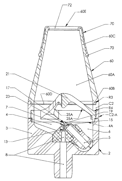
Figure 9, shows, according to particular aspects of the present invention, a
perspective view
of another exemplary nasal adaptor embodiment.
Figure 10, shows, according to particular aspects of the present invention, a
perspective
view of an exemplary ocular adaptor embodiment.
Figure 11, shows, according to particular aspects of the present invention, a
side cross-
sectional view of an exemplary ocular atomizer embodiment, comprising:
atomization means;
aerodynamic particle size filtering means; particle dispersion chamber; and
ocular adapter.
Figure 12 shows, according to particular aspects of the present invention, a
side cross
sectional view of yet another exemplary nasal atomizer embodiment, comprising:
atomization
means; aerodynamic particle size filtering means; and particle dispersion
chamber.
Figure 13 shows, according to particular aspects of the present invention, a
side cross
sectional view of yet another exemplary nasal atomizer embodiment, comprising:
atomization
means; atomization chamber; aerodynamic particle size filtering means; and a
nasal adapter having
a second interface portion configured to be inserted into a nostril.
Figure 14 shows, according to particular aspects of the present invention, a
side cross
sectional view of yet another exemplary nasal atomizer embodiment, comprising:
atomization
21
CA 02698137 2010-03-01
WO 2008/028092 PCT/US2007/077319
means; atomization chamber; aerodynamic particle size filtering means;
particle dispersion
chamber; a second intermediate compressed fluid channel, and a nasal adapter
having an interface
portion configured to be inserted into a nostril.
Figure 15A shows, according to particular aspects of the present invention, an
elevational
perspective view of an exemplary embodiment of a nasal adapter having a second
interface portion
configured to be inserted into a nostril.
Figure 15B shows, according to particular aspects of the present invention, an
elevational
perspective view of another exemplary embodiment of a nasal adapter configured
for dual delivery
and having a pair of second interface portions each configured to be inserted
into one of the nostrils
of a user.
Figure 16 shows, according to particular aspects of the present invention, an
elevational
perspective view of another exemplary embodiment of a nasal adapter having a
second interface
portion configured to be inserted into a nostril.
Figure 17 shows, according to particular aspects of the present invention, an
elevational
perspective view of another exemplary embodiment of a nasal adapter having a
second interface
portion configured to be inserted into a nostril.
Figure 18 shows, according to particular aspects of the present invention, a
side cross
sectional view of an exemplary oral atomizer embodiment, comprising:
atomization means;
atomization chamber; aerodynamic particle size filtering means; and an oral
adapter.
Figure 19 shows, according to particular aspects of the present invention, a
side cross
sectional view of another exemplary oral atomizer embodiment, comprising:
atomization means;
atomization chamber; aerodynamic particle size filtering means; particle
dispersion chamber; an
intermediate compressed fluid channel, and an oral adapter.
Figure 20 shows, according to particular aspects of the present invention, an
elevational
perspective view of an exemplary embodiment of an oral adapter having a
mouthpiece configured
to be inserted into the mouth of a user. . Such laterally deflecting
embodiments also serve as
vicinity adapters for delivery of aerosolized particles to the vicinity of a
user or to desired target
22
CA 02698137 2010-03-01
WO 2008/028092 PCT/US2007/077319
surfaces (e.g., for delivery of perfume, fragrance, essential oil or
cosmeceutical agent and the like).
Figure 21 shows, according to particular aspects of the present invention, an
elevational
perspective view of an exemplary embodiment of an oral adapter having a
mouthpiece configured
to be inserted into the mouth of a user. Such laterally deflecting embodiments
also serve as vicinity
adapters for delivery of aerosolized particles to the vicinity of a user or to
target surfaces (e.g., for
delivery of perfume, fragrance, essential oil or cosmeceutical agent and the
like).
Figure 22 shows, according to particular aspects of the present invention, a
side view of
another exemplary embodiment of a dispersion chamber and/or a delivery adapter
(e.g., a dispersion
chamber and/or a vicinity adapter for delivery of aerosolized particles to the
vicinity of a user or to
desired target surfaces (e.g., for delivery of perfume, fragrance, essential
oil or cosmeceutical agent
and the like)).
Figure 23 shows, according to particular aspects of the present invention, a
side cross-
sectional view of an additional exemplary atomizer embodiment, comprising:
atomization means;
particle dispersion chamber and/or vicinity adapter; and angled removable
(e.g., modular) liquid
holding container with upper and lower apertures for liquid return and liquid
entrainment,
respectively.
Figure 24 shows a side elevational exploded sectional view of the exemplary
embodiment of
Figure 23.
Figure 25 shows, according to particular aspects of the present invention, a
side cross-
sectional view of an additional exemplary atomizer embodiment, comprising:
atomization means;
particle dispersion chamber and/or vicinity adapter; removable internal
container, and external
modular liquid holding container.
Figure 26 shows a side elevational exploded sectional view of the exemplary
embodiment of
Figure 25.
DETAILED DESCRIPTION OF THE INVENTION
Aspects of the present invention include aerosol generating and related
delivery devices,
23
CA 02698137 2010-03-01
WO 2008/028092 PCT/US2007/077319
such as atomizers and nebulizers. Further aspects include a filter member
configured for use with
such devices. Additional aspects include integrated atomizer and particle
dispersion chamber
apparatuses. The technology disclosed herein may have medical applications as
well as non-
medical applications. Further, various adapters may be used to configure the
technology to deliver
aerosolized particles to specific areas of the human body as well as to
configure the technology for
specific purposes (e.g., delivery of aerosolized particles to the vicinity of
a user or to a target
surface).
With respect to exemplary medical uses, prior art topical drug delivery
methods are
ineffective at penetrating very far into the nasal cavity and not at all into
the paranasal sinuses. This
is a significant limitation/problem, because systemic delivery via inhalation
utilizing the nasal
mucosa and mucosa in the paranasal sinuses is highly desirable for many
targeted disease states.
Preferred aspects of the present invention provide novel atomizers, and novel
integrated
atomizers and particle dispersion chamber apparatuses that have the ability to
deliver medicaments
(e.g., such as the drugs presently prescribed for many diseases and
conditions) as doses of very tiny
medicine-containing particles over a broad particle range, and with medicament
having significant
viscosity. Inventive effective delivery is, for example, by using a nasal
adapter that, in combination
with the inventive particle generation and dispersion aspects, allows more
efficacious topical and
systemic targeted delivery within the nasal cavity and regions thereof of a
user. Alternatively,
effective inventive delivery may be by an ocular adaptor, oral adapter,
vicinity adapter and the like.
Examples of diseases and/or conditions that can be treated by medicament
delivery using the
inventive apparatus and methods include, but are not limited to, endocrine and
metabolic disorders,
sinusitis, infection, migraines, sleep disorders, autoimmune diseases,
osteoporosis, neurological
diseases and disorders, obesity, sexual dysfunctions, diabetes, cardiovascular
diseases and episodes,
respiratory diseases, cystic fibrosis, cancer, ocular diseases and /or
conditions including, but not
limited to allergies, conjunctivitis, corneal infections, dry eye, Fuchs'
Dystrophy, and others. Any
of the aforementioned diseases and/or conditions that require systemic
delivery of medications
could also be treated through the mouth. The inventive devices can also be
used for aerosolized
24
CA 02698137 2010-03-01
WO 2008/028092 PCT/US2007/077319
antigen-mediated immunization, vaccination, etc.
According to preferred aspects, the particle size (e.g., MMAD particle
distribution), particle
dispersion technology (e.g., velocity vector pattern), and duration of
application allow the medicine
to reach and permeate the targeted area of the nasal cavity, and thus enable
effective systemic
delivery of medicament via the nasal cavity, eye, cheeks, and the like. For
example, essentially any
and all medicines currently applied (e.g., by direct action) to the nasal
cavity and paranasal sinuses,
including relatively viscous medicines and solutions, can be used or adapted
(e.g., formulated) for
use with the inventive atomizer and/or integrated atomizer embodiments,
including but not limited
to over-the-counter nasal medicines (e.g., for allergy and colds and flu) and
prescription medicines.
Similarly, essentially any and all medicines currently applied (e.g., by
direct action) to the
surface of the eye, can be used or adapted (e.g., formulated) for use with the
inventive atomizer
and/or integrated atomizer embodiments, including but not limited to over-the-
counter ocular
medicines (e.g., for allergies and eye irritation) and prescription medicines.
Further, essentially any
and all medicines currently applied (e.g., by direct action) to the inside of
the mouth (e.g., the inside
of the cheeks), can be used or adapted (e.g., formulated) for use with the
inventive atomizer and/or
integrated atomizer embodiments, including but not limited to over-the-counter
nasal or oral
medicines (e.g., for allergies and sores) and prescription medicines.
Additionally, medicines
currently delivered/taken orally, by skin patch, or parenterally can be
adapted (e.g., formulated) for
delivery use using the inventive atomizer and integrated atomizer embodiments.
In particular
embodiments, the technology disclosed herein may be used to generate a cloud
or fog of atomized
particles or droplets that may be exposed to the skin. Following exposure, one
or more liquids,
such as a liquid solvent, included in the atomized particles or droplets may
dry leaving materials
(e.g., medicines, perfume, fragrance, essential oil or cosmeceutical agents,
lotions, and the like)
behind on the skin, which may remain on the surface of the skin or be absorbed
thereby.
Alternatively, the user's skin may absorb one or more of the liquids included
in the atomized
particles or droplets.
Among the many enabled utilities, the instant devices can be used for delivery
of drugs to
CA 02698137 2010-03-01
WO 2008/028092 PCT/US2007/077319
the brain to treat conditions of the central nervous system (CNS); so-called
`Nose-to-Brain'
delivery. In this process, drugs delivered to the olfactory region of the
nasal cavity (e.g., delivered
very high through small passages) can enter the brain and bypass the so-called
blood brain barrier.
This inventive utility provides a very significant, here-to-fore unavailable
method of drug delivery.
Significantly, to achieve nose-to-brain delivery, the delivery device must be
capable of efficiently
providing a dynamic particle population suitable to target and reach this
area. Significantly,
according to preferred aspects, the inventive integrated atomizer has
substantial utility for both
topical and systemic delivery of drugs, therapeutics, and other beneficial
compounds, and provides
for nose-to-brain delivery of drugs, therapeutics and other beneficial
compounds.
In particular aspects, and for a user with a secondary condition of nasal
polyps, the inventive
apparatus and methods allow far more effective application of medicine, which
is otherwise blocked
or precluded by such secondary conditions using contemporary systems. For
example, prior art
nasal inhalers and spray bottles are used to deliver corticosteroids, which,
at least in theory, is
designed to slow re-growth of polyps subsequent to polyp removal. Currently,
however, such
devices are largely ineffective at accomplishing this, often not slowing polyp
growth at all.
According to preferred aspects, the inventive apparatus and methods described
herein provide for
substantially improved and more effective slowing of such polyp re-growth.
According to additional aspects, many of the side effects of particular
medicine delivery are
precluded or eradicated by the inventive devices and methods. With many
sprays, for example, the
propellant causes a drying of the nasal passages leading to bleeds. Therefore,
with such
applications, a secondary spray of saline is added to the treatment in an
attempt to control such
bleeding. Additionally, for example, steroids in pill form have many
unpleasant side effects such as
internal bleeding, a redistribution of fluid to the head, neck and back
causing unsightly "humps,"
and easy bruising, to name a few. An effective use of the inventive integrated
atomizer for such
steroid delivery does not have these attendant pill-based side effects.
Current nasal drug delivery devices deliver droplets in a range from 50 m to
100 m.
Significantly, due to the size of the droplets and the physical
characteristics of the nasal cavity, the
26
CA 02698137 2010-03-01
WO 2008/028092 PCT/US2007/077319
maximum dose that can be delivered is 200 l per nostril. This limitation on
the deliverable amount
of medicament volume (e.g., mass) restricts the formulation characteristics
and limits additives that
could assist in achieving the goals of the medication. By contrast, because of
its unique and novel
configuration, the inventive atomizer generates droplets that are much
smaller, and substantially
more suitable for deposition on a much larger surface area of the nasal
cavity, particularly when an
inventive integrated atomizer is used. The inventive atomizer, therefore, can
deliver doses up to 2
ml to the nasal cavity, thus allowing for use of optimal/superior formulations
and effectiveness.
The inventive devices could also be used to deliver aromatherapy. For example,
the
inventive apparatuses could be used to expel aerosolized particles into the
air (e.g., in the vicinity of
the user). These particles are then be perceived by the user located an
appropriate distance from the
device for an appropriate amount of time to receive a therapeutically
significant quantity of
aerosolized particles.
Non-medical uses include the aerosolization of perfume, fragrance, essential
oil or
cosmeceutical agents and the like. By way of example, the inventive
apparatuses could be used to
expel a cloud of aerosolized particles into the air through which the user to
could pass his/her skin,
clothes, and/or hair, thereby allowing a portion of the aerosolized particles
to settle thereupon.
Alternatively, the devices could be used to target surfaces with such
aerosolized particles. Flavored
particles could be delivered (e.g., to the tongue or nasal cavity, or to other
surfaces). Adhesives
could be delivered. Paints could be delivered.
Overview
With reference to FIGURES 2-4 and the definitions provided below, an overview
of
aspects of the present invention will now be described. An exemplary
embodiment of an atomizer 1
configured for nasal delivery of aerosolized particles is shown in FIGURE 2.
The atomizer 1
includes an atomization housing 2 defining an atomization chamber 4 in
communication with, or
comprising holding means (e.g., a reservoir portion 6) suitable for holding a
liquid (e.g.,
27
CA 02698137 2010-03-01
WO 2008/028092 PCT/US2007/077319
medicament solution), which can be filled to one or another suitable level
(e.g., consistent with the
configuration, and desired dosage, etc.) identified or marked by reference
numeral 9 (Figure 3).
The atomizer 1 may include an atomization means 11 housed inside the
atomization housing
2. The atomization means 11 includes a primary liquid feed channel 15 in
communication with the
liquid held in the holding means. The primary liquid feed channel 15 may
receive the liquid from a
secondary liquid feed channel 5 that is in fluid communication with the
holding means (e.g., the
reservoir portion 6). In other words, the secondary liquid feed channel 5 is
intermediate between
the primary liquid feed channel 15 and the holding means.
The atomization means 11 may be optionally driven by a compressed fluid source
(not
shown), inhalation, and the like. For convenience of illustration, the
compressed fluid driven
embodiments will described first. In such embodiments, the atomization means
11 includes a
primary compressed fluid channel 13 in communication with an external or
internal compressed
fluid source (not shown). As may best be viewed in FIGURE 4, the primary
compressed fluid
channel 13 has a corresponding orifice 7 defining a projectable longitudinal
compressed fluid feed
channel axis "F," in operative communication with the primary liquid feed
channel 15 and its
corresponding orifice 17. The primary compressed fluid channel 13 receives
compressed fluid from
a secondary compressed fluid channel 8 in fluid communication with the
compressed fluid source
(not shown). In other words, the secondary compressed fluid channel 8 is
intermediate between the
primary compressed fluid channel 13 and a source of compressed fluid. The
atomization means 11
is suitably configured to entrain a liquid in a fluid flow stream (not shown)
to generate a particle
(e.g., aerosolized liquid droplet) flow along (e.g., centered along) the
projected axis "F."
In embodiments driven by inhalation, the secondary compressed fluid channel 8
may be
open to the ambient air and inhalation by the user may draw ambient air into
the secondary
compressed fluid channel 8 and the primary compressed fluid channel 13 couple
thereto. In such
embodiments, the "compressed fluid" in the primary compressed fluid channel 13
may include air
drawn into the device by the user's inhalation.
28
CA 02698137 2010-03-01
WO 2008/028092 PCT/US2007/077319
Returning to FIGURE 2, the atomizer 1 may include an aerodynamic particle-size
filtering
means or filtering member 21 (e.g., air-foil member) suitably configured and
positioned at a
distance "J" from the primary orifice plane "P" (defined by the primary
compressed fluid orifice 7
in a manner explained below) to direct fluid flow around its contour, and
thereby non-collisionally
redirect particle flow of the desired particle size range around its contour,
while simultaneously
blocking larger particles for return to the liquid reservoir and re-
entrainment. In other words, the
filtering member 21 separates particles having a size larger than a
predetermined size from particles
having a size less than or equal to the predetermined size. The particles
having a size larger than
the predetermined size are collected by the filtering member 21 and returned
to the holding means.
The particles having a size less than or equal to the predetermined size pass
by the filtering member
21.
Optionally, the atomizer 1 may include a particle dispersion chamber 10 having
an optional
dispersion chamber outer housing 28, an optional intermediate compressed fluid
channe140, various
connector components used to couple these components to the atomization
chamber 4, and the like.
The dispersion chamber outer housing 28 may be optionally fitted with a nasal
adapter 42 (see
FIGURES 2 and 7-9), a nasal adapter 60 (see FIGURES 13-17), an ocular adapter
48 (see
FIGURES 10 and 11), an oral adapter (see FIGURES 18-21), and the like. As is
apparent to those
of ordinary skill, atomizers and nebulizers may be configured for use with
various accessories,
adapters, and the like and the invention is not limited to use with any
particular accessories,
adapters, and the like.
Definitions:
The term "liquid," as used herein with respect to a liquid to be atomized
using the inventive
devices and methods, refers to any liquid or solution, including medicament
solutions and drug or
agent formulations and solutions. Liquid also encompasses liquids and
solutions of various
viscosities.
The terms "particle filter," "particle size filter" (e.g., aerodynamically
particle size filtering
29
CA 02698137 2010-03-01
WO 2008/028092 PCT/US2007/077319
means), and "splitting means," as used herein, refer to a particle filter
(e.g., an aerodynamic particle
size filtering member) suitably configured and positioned at the distance "J"
from the primary
compressed fluid orifice 7 (e.g., from a primary orifice plane "P", as defined
herein) to provide an
aerodynamic fluid flow around the surface. Preferably, the particle filter,
and/or the configuration
and placement thereof, provides for a proportion of atomized particles that
collide with the member
and a proportion of non-colliding particles with velocity vectors that avoid
the surface and/or are
carried in the aerodynamic fluid flow around the surface.
The term "holding means" as used herein, refers to a liquid or solution
reservoir (e.g., the
reservoir portion 6) for holding the liquid or solution to be atomized. Liquid
or solution in the
holding means is in communication with the atomization means 11 via one or
more liquid feed
channels (e.g., the secondary liquid feed channel 5). In preferred
embodiments, the holding means
is configured so that impaction liquid from the inventive filtering member 21
is returnable to the
holding means for re-entrainment by the atomization means 11. The holding
means can be of any
suitable configuration, and, for example, can be configured as part of the
atomization chamber 4 per
se, or alternatively can be a holding means (e.g., a cartridge, vial or other
liquid, solution or
medicament container) that is insertable into the atomization chamber 4 so
that a liquid, solution or
medicament contained therein is in communication with the atomization means
11.
The term "primary orifice plane `P"' as used herein with respect to particular
exemplary
embodiments, refers to a positional reference plane normal to the projectable
longitudinal
compressed fluid feed channel axis "F", definable by the configuration and
contour of a perimeter
7A (e.g., circular perimeter, or otherwise) of the primary compressed fluid
orifice 7. As shown in
the exemplary embodiments described herein, the perimeter 7A of the primary
compressed fluid
orifice 7 defines a normal, horizontal surface, for which the reference
primary orifice plane "P"
provide direct reference (e.g., for purposes of describing the distance of a
filtering member 21 or
other element along the axis "F"). It should be understood, however, that the
precise shape of the
perimeter 7A of the primary compressed fluid orifice 7 may be other than the
exemplary regular,
normal or horizontal shape and may assume a variety of suitable
configurations, and in such cases
CA 02698137 2010-03-01
WO 2008/028092 PCT/US2007/077319
the positional reference plane (i.e., the primary orifice plane "P") will
still be normal to the
projectable longitudinal compressed fluid feed channel axis "F", but will be
positioned along the
axis "F" at the median position along axis "F" of the primary compressed fluid
orifice 7, regardless
of the regularity, shape, slope, configuration, etc., thereof. For example, if
the primary compressed
fluid orifice 7 is circular, but is angled (slopped) rather than normal to the
axis "F", then primary
orifice plane "P" will be a plane "P" positioned normal to axis "F", but at a
position along axis "F"
corresponding to the center point of the primary compressed fluid orifice 7.
In this manner, the
primary orifice plane "P" serves its reference position function with respect
to defining a distance to
other elements of the inventive devices.
The term "channel end-wall face" as used herein with respect to particular
exemplary
embodiments, refers to a positional reference plane definable by the
configuration and contour of a
perimeter 17A of the primary liquid feed channel orifice 17 and the
configuration and contour of an
end-wall face 23 of the primary liquid feed channel 15. The end-wall face 23
having a perimeter
23A. As shown in particular exemplary preferred embodiments described herein,
the perimeter
17A of the primary liquid feed channel orifice 17 and the perimeter 23A of the
end-wall face 23
define a surface 17C that is normal to a liquid feed channel axis "L," and
that is disposed at an
acute angle "A" with respect to the axis "F." It should be understood,
however, that the precise
shape of the perimeter 17A of the primary compressed fluid orifice 17 and/or
the perimeter 23A of
the end-wall face 23 may be other than the exemplary regular, normal or
horizontal or angled shape
and may assume a variety of suitable configurations, and in such cases the end-
wall face 23, regular
or irregular, may be other that normal to the projectable longitudinal liquid
feed channel axis "L".
For example, if the primary liquid feed channel orifice 17 and end-wall face
23 is circular, but is but
is horizontal (e.g., normal with respect to the axis "F"), then the orifice 17
and end wall face 23 (or
a plane representing the average configuration/shape of the orifice and end-
wall face) will be
normal to axis "F", but at an angel with respect to axis "L". Therefore, a
variety of suitable shapes
and configurations of the primary compressed fluid orifice 17 and/or the end-
wall face 23 are
encompassed by the present invention, and these may be disposed at various
angels with respect to
31
CA 02698137 2010-03-01
WO 2008/028092 PCT/US2007/077319
the axis "F." Therefore, for purposes of the present invention, the
positioning, with respect to the
projectable axis "F", of the end-wall face 23 and orifice 17 thereof are
defined by the positioning,
normal to axis "F," of a closest plane "I"-intersecting portion 23B of the
perimeter 23A of the end-
wall face 23, where plane "I" is a plane defined by the intersection of the
axis "F" with the axis "L".
In this manner, the distance of the perimeter 23A of the end-wall face 23 from
the axis "F" can be
defined, regardless of the shape, configuration, or orientation of the end-
wall face 23 and the
primary liquid feed channel orifice 17 thereof.
ATOMIZATION MEANS 11
As mentioned above, the atomization housing 2 houses the atomization means 11
and
defines an atomization chamber 4 in communication with, or comprising holding
means.
Alternatively, the atomization means 11 may include a housing 2A having a
wa112C defining the
atomization chamber 4 in which the liquid or solution is atomizable. In the
embodiment depicted in
FIGURE 2, the atomization chamber 4 includes a reservoir portion 6 that serves
as the holding
means suitable for holding a liquid or solution to be atomized.
With reference to FIGURES 2, 3, and 4, to allow for compressed fluid-driven
(e.g.,
compressed air-driven) particle generation, the atomization chamber 4 is in
communication with the
compressed fluid source (e.g., an air compressor, tank, compressed gas
cartridge, and the like) via
the primary compressed fluid orifice 7, the primary compressed fluid feed
channel 13, and, in
certain embodiments, a secondary compressed fluid channel 8 that communicates
between the
primary compressed fluid feed channel 13 and the source of compressed fluid.
The primary
compressed fluid orifice 7 is located at a first end 13A of the primary
compressed fluid feed channel
13, is in fluid communication with the atomization chamber 4, and defines the
primary orifice plane
"P." A second open end 13B opposite the first end 13A of the channe113 is in
fluid communication
with the compressed fluid source (e.g., an air compressor), which may, in
certain embodiments,
may be via the secondary compressed fluid channel 8. The channel 13 and/or
orifice 7 define the
projectable compressed fluid feed channel axis "F."
32
CA 02698137 2010-03-01
WO 2008/028092 PCT/US2007/077319
The primary compressed fluid feed channe113 (e.g., cylinder, tube, channel,
bore, etc.) has a
length "Ll," an inner diameter "Dl." The secondary compressed fluid channel 8
has an inner
diameter "D5" and a length "L4" (see FIGURE 3). In the embodiment depicted in
the drawings,
the secondary compressed fluid channel 8 has a first portion 8A coupled to the
channel 13 and a
second larger diameter portion 8B coupled between the first portion 8A and the
compressed fluid
source (not shown). In the embodiment depicted in FIGURE 2, compressed fluid
is supplied to the
atomization chamber 4 via a channel having three segments of decreasing inner
diameter (i.e., the
second portion 8B, the first portion 8A, and the primary compressed fluid
channe113). However, as
is apparent to those of ordinary skill in the art, embodiments in which the
inner diameter "D5" of
the first portion 8A is greater than or substantially equal to the inner
diameter of the second portion
8B are also within the scope of the present invention.
As may best be viewed in FIGURE 4, the primary liquid feed channel 15 (e.g.,
cylinder,
tube, channel, bore, etc.) has a length "L2," an inner diameter "D2,"a channel
wall 19, and a
channel end-wall face 23 at a first end 15A. The channel 15 also includes an
outside diameter "D3"
disposed about (e.g., radially about) the primary liquid feed channel orifice
17 in fluid
communication with the atomization chamber 4. The primary liquid feed channel
15 has a second
end 15B in optional communication with a secondary liquid feed channel 5
having a length "L3"
(see FIGURE 3) and an inner diameter "D4." The secondary liquid feed channel 5
is in
communication with the liquid holding means 6. The primary liquid feed channel
15 defines a
projectable longitudinal liquid feed channel axis "L."
According to preferred aspects, the inventive, highly efficient atomization
means 11 is
uniquely configured such that: (a) the channel end wall face 23 with the
liquid feed channel
orifice 17 is separated by at least a distance "H" (e.g., vertical distance or
height, in the case of
vertically oriented embodiments) from the a primary orifice plane "P," the
distance "H" being
measured along the projected longitudinal axis "F"; and (b) the longitudinal
axis "L" intersects the
longitudinal axis "F" at the acute angle "A." In preferred embodiments, and at
the distance "H"
along the axis "F," the plane "I"-intersecting portion 23B of the perimeter
23A of the end wall face
33
CA 02698137 2010-03-01
WO 2008/028092 PCT/US2007/077319
23 is positioned within a selected distance "S" from axis "F" (measured
perpendicular to the
axis "F") and this distance is sometimes referred to herein as the offset
distance "0."
In some embodiments, the selected distance "S" is such that there is `overlap'
of axis "F"
with the plane "I"-intersecting portion 23B of the perimeter 23A of the end
wall face 23, where, as
used herein, there is `overlap,' if the projected axis "F" intersects the end
wall face 23 or the liquid
feed channel orifice 17 thereof. In such overlapping embodiments the selected
distance "S" is
sometimes referred to herein as a negative offset "minus 0" distance. When
there is negative offset
(i.e., a minus 0 distance), the orifice 7 is positioned adjacent to a
diverting portion 19A of the wall
19 of the primary liquid feed channel 15 aligning at least a portion of the
flow of compressed fluid
along axis "F" with the diverting portion 19A of the wall 19 and causing a
first portion of the
compressed fluid to strike (or impact) the diverting portion 19A of the wall
19. A portion of the
compressed fluid is also directed around the outside of the diverting portion
19A of the wall 19.
Without being limited by theory, directing the flow of compressed fluid around
the diverting
portion 19A may disrupt or spread the column of compressed fluid leaving the
orifice 7. Therefore,
unlike prior art or conventional atomizers and nebulizers that avoid spreading
or disrupting the flow
of compressed fluid before it strikes the impactor thereby maximizing the
portion of the flow of
atomized particles that strike the impactor, certain embodiments of the
present invention spread the
flow of compressed fluid before it engages the liquid to be atomized.
In various embodiments, outside of the diverting portion 19A of the wall 19
may be
contoured. As the compressed fluid traverses the contoured surface, the
velocity of the fluid is
increased and pressure around the diverting portion 19A of the wall 19 may
decrease to below that
of the uninterrupted flow of compressed fluid. In the embodiment depicted in
FIGURE 4, the
orifice 7, channel 15, and wall 19 thereof are arranged such at the orifice 7
extends substantially
between the portion 23B of the perimeter 23A of the channel end face 23 and
the center of the
channel 15 along plane "P." In this embodiment, the compressed fluid will be
traveling at different
rates along the diverting portion 19A in the axial direction of axis "F."
Specifically, the fluid will
34
CA 02698137 2010-03-01
WO 2008/028092 PCT/US2007/077319
be traveling faster near the center of the orifice 7 than near the portion 23B
of the perimeter 23A of
the end wall face 23 where it traverses a smaller portion of the diverting
portion 19A.
In other embodiments, the selected distance "S" is such that there is no
`overlap' of axis "F"
with the plane "I"-intersecting portion 23B of the perimeter 23A of the end
wall face 23 (i.e., the
projected axis "F" does not intersect the end wall face 23 or the liquid feed
channel orifice 17
thereof). In such non-overlapping embodiments, the selected distance "S" is
sometimes referred to
herein as a positive offset "plus 0" distance.
In particular embodiments, the selected distance "S" from projected axis "F"
is less than or
equal to 1/2 x Dl, and in instances where there is no overlap as defined
herein, this distance would
correspond to a "plus 0" value that is less than or equal to 1/2 x Dl. In
alternate embodiments, the
selected distance "S" from projected axis "F" is less than or equal to 1/2 x
Dl, and in instances where
there is overlap as defined herein, this distance would correspond to a "minus
0" value that is less
than or equal to 1/2 x Dl (see, e.g., "0" in FIGURE 4). In particular
embodiments, offset distance
"0" (plus or minus) is less, equal to or greater than 1/2 x Dl. In particular
embodiments, offset
distance "0" (plus or minus) is less than 1/2 x Dl, and preferably "minus 0"
is less than 1/2 x Dl. In
particular embodiments, neither the plane-I-intersecting portion 23B of the
perimeter 23A of the
end wall face 23 nor a plane-I-intersecting portion 17B of the perimeter 17A
of the liquid feed
channel orifice 17 overlap projected axis "F." In other embodiments, the plane-
I-intersecting
portion 23B of the perimeter 23A of the end wall face 23 overlaps projected
axis "F," whereas the
plane-I-intersecting portion 17B of the perimeter 17A of the liquid feed
channel orifice 17 does not.
In yet additional embodiments, both the plane-I-intersecting portion 23B of
the perimeter 23A of
the end wall face 23 and the plane-I-intersecting portion 17B of the perimeter
17A of the liquid feed
channel orifice 17 overlap projected axis "F" (i.e., the projected axis "F"
intersects the liquid feed
channel orifice 17 of the end wall face 23).
It will be appreciated by those of skill in the art that the precise shape of
the primary
compressed fluid orifice 7 and/or the primary liquid feed orifice 17 may vary
(e.g., circular, ovoid,
rectangular, square, etc.), and that the present inventive aspects encompass
such variations, and that
CA 02698137 2010-03-01
WO 2008/028092 PCT/US2007/077319
the shapes may be regular (e.g., flat, smooth, gently curved) or irregular
(jagged, abruptly curved,
rough, etc.). Additionally, it will be appreciated by those of skill in the
art that the precise angular
disposition of the primary compressed fluid orifice 7 and/or the primary
liquid feed orifice 17 with
respect to the axis "F" and axis "L", respectively, may vary (e.g., normal,
acute, obtuse), and that
the present inventive aspects encompass such variations.
In particular embodiments, distance "H" is less than diameter "Dl," equal to
diameter "Dl,"
or greater than diameter "Dl." In particular embodiments, distance "H" is
greater than diameter
"Dl." Preferably, distance "H" is equal to or greater than diameter "Dl."
In some embodiments, distance "H" is less than diameter "D2," equal to
diameter "D2," or
greater than diameter "D2." In some embodiments, distance "H" is greater than
diameter "D2."
Preferably, distance "H" is equal to or greater than diameter "D2."
In particular embodiments, distance "H" is less than diameter "D3," equal to
diameter "D3,"
or greater than diameter "D3." In some embodiments, distance "H" is less than
diameter "D3."
Preferably, distance "H" is equal to or less than diameter "D3."
In some embodiments, distance "H" is less than diameter "D3," but greater than
diameter
"Dl," or distance "H" is less than diameter "D3," but greater than diameter
"D2." In some
embodiments, diameter "D2" is equal to or greater than diameter "Dl." In some
embodiments, the
distance "H" is equal to or greater than 1/4, 1/2 or 1 x the inner diameter "D
1" of the primary
compressed fluid feed channel 13. In particular aspects, distance "H" is less
than diameter "D3,"
and greater than both diameter "Dl" and diameter "D2." In some embodiments,
distance "H" is
greater than any one of diameter "Dl," diameter "D2," and diameter "D3."
In particular embodiments, the atomization means 11 is configured such that,
during
operation of the atomization device 1, the longitudinal primary fluid feed
channel axis "F" of the
primary compressed fluid feed channel 13 is vertically oriented, or
substantially vertical (e.g.,
within 5 or 10 degrees of vertical), within the atomization chamber 4.
36
CA 02698137 2010-03-01
WO 2008/028092 PCT/US2007/077319
In particular embodiments, the diameter "Dl" of the primary orifice 7 is from
about 0.1 mm
to about 1 mm, about 0.2 mm to about 0.6 mm, about 0.25 mm to about 0.4 mm, or
preferably about
0.29 mm to about 0.46 mm.
In particular embodiments, the diameter "D2" of the primary liquid feed
channel orifice 17
is from about 0.15 mm to about 1.5 mm, about 0.25 mm to about 1.0 mm, about
0.3 mm to about
0.75 mm, or preferably about 0.38 mm to about 0.50 mm.
In particular embodiments, the outer diameter "D3" of the primary liquid feed
channel end
wall face 23 is from about 0.2 mm to about 4.0 mm, about 0.4 mm to about 3.0
mm, about 0.6 mm
to about 2.5 mm, or preferably about 0.76 mm to about 2.03 mm.
In other embodiments, diameter "D4" is from about 2 mm to about 2.5 mm. In
various
embodiments, the inner diameter "D4" is larger than the inner diameter "D2" of
the primary liquid
feed channel. In particular aspects, diameter "D4" is greater than or equal to
2 x D2, 3 x D2, 4 x
D2, 5 x D2, 10 x D2, 15 x D2, 20 x D2, 30 x D2, 40 x D2 or 50 x D2. In
particular embodiments, in
inside diameter "D4" of the secondary liquid feed channel 5 is from about 1.5
mm to about 4 mm,
about 1.5 mm to about 3 mm, or about 1.5 mm to about 2.5 mm. In some aspects,
diameter "D4" is
from about 1 mm to about 5 mm, from about 1.5 mm to about 3 mm, or from about
2 mm to about
2.5 mm. In such preferred embodiments, the relatively large diameter "D4"
(i.e., relative to prior
art atomization and nebulization devices which have relatively narrow liquid
channels) enables
atomization and delivery of relatively viscous liquids (e.g., 5-105
centipoise) and solutions that
cannot be effectively atomized, nebulized or delivered by devices of the prior
art (which cannot
effectively atomize, nebulize or deliver particles greater than about 5
centipoise). According to
preferred aspects, diameter "D4" is greater than the diameter of corresponding
primary and
secondary liquid feed channels of conventional prior art atomizers and
nebulizers, thereby reducing
the liquid flow resistance relative to prior art devices, and allowing for
effective atomization and
delivery of liquids of substantially increased viscosity relative to those
liquids effectively
atomizable or nebulizable by prior art devices. This also facilitates a higher
rate of delivery (more
mass delivered per unit time, relative to prior art devices).In particular
embodiments, the distance
37
CA 02698137 2010-03-01
WO 2008/028092 PCT/US2007/077319
"H" from the primary orifice plane "P" ranges from about 0.02 mm to about 5.0
mm, about 0.1 mm
to about 5.0 mm, about 0.15 mm to about 4.0 mm, about 0.2 mm to about 3.0 mm,
or preferably
about 0.25 mm to about 2.03 mm.
In particular embodiments, the selected distance "S" or the offset distance
"0" (plus or
minus) from longitudinal axis "F" is less than, equal to, or greater than 1/2
x Dl. Preferably, selected
distance "S" or offset distance "0" (plus or minus) is less than or equal to
1/2 x Dl. More
preferably, selected distance "S" or offset distance "0" (plus or minus) is
less than 1/2 x Dl. The
selected distance "S" may be equal to or less than twice the inner diameter
"D1" of the primary
compressed fluid feed channel 13.
In particular embodiments, the angle "A" is between about 30 degrees and about
70 degrees,
between about 45 degrees and about 70 degrees, or between about 55 degrees and
about 65 degrees.
In some embodiments, the angle "A" is about 55 degrees.
In particular embodiments, the distance "J" from the primary orifice plane "P"
ranges from
about 0.1 mm to about 40 mm, 0.1 mm to about 25 mm, 0.1 mm to about 5.0 mm,
about 0.15 mm to
about 4.0 mm, about 0.2 mm to about 3.0 mm, or preferably about 0.25 mm to
about 2.0 mm.
DISPERSION CHAMBER 10
The linear atomizer embodiment 1 of FIGURE 2 additionally comprises a particle
dispersion
chamber 10 in fluid communication with the atomization means 11 of the
atomization chamber 4.
The particle dispersion chamber 10 imparts a velocity vector or flow pattern
(e.g., `vortical,'
randomized, turbulent, etc. flow) to the aerosolized particles (e.g., atomized
particles) received
within and exiting from the particle dispersion chamber 10. Additionally, the
particle dispersion
chamber 10 serves to define further the particle size after the droplets are
created by and received
from the atomization means 11.
The particle dispersion chamber 10 comprises a housing 16 having a wall 16A,
an
atomization chamber-proximal input opening 16B, an atomization chamber-distal
output opening
16C, and an internal particle dispersion channel 22 communicating between the
input opening 16B
and the output opening 16C. The input opening 16B is in fluid communication
with the
38
CA 02698137 2010-03-01
WO 2008/028092 PCT/US2007/077319
atomization chamber 4 and the particle dispersion chamber 10 is configured to
operatively receive
atomized particles therethrough from the atomization means 11. The atomization
chamber 4
includes an open portion 4A through which atomized particles may exit the
atomization chamber 4
and the particle dispersion chamber 10 includes an atomization chamber-
proximal input opening
16B through which atomized particles may enter the particle dispersion chamber
10.
In the embodiments depicted in FIGURES 2, 7, and 11, the input opening 16B of
the
particle dispersion chamber 10 is coupled directly to the open portion 4A of
the atomization
chamber 4 to allow the passage of atomized particles from the atomization
chamber 4 to the particle
dispersion chamber 10. For example, the open portion 4A may be formed in the
top of the
atomization chamber 4 and the particle dispersion chamber 10 attached to the
top of the atomization
chamber 4 with its input opening 16B juxtaposed with the open portion 4A of
the atomization
chamber 4.
In alternate embodiments depicted in FIGURES 12, 14, and 19, a connector or
collar "Cl"
is disposed between the particle dispersion chamber 10 and the atomization
chamber 4. The
collar "Cl" may include a recessed portion "Rl" configured to receive a
portion of the particle
dispersion chamber 10 and position the input opening 16B of the particle
dispersion chamber 10
adjacent to the open portion 4A formed in the top of the atomization chamber
4.
The particle dispersion chamber 10 may additionally include, or communicate
with, an
aerodynamic particle size filtering member, `splitter' member, or filtering
member 21, suitably
configured and positioned at a distance from the primary orifice plane "P"
(defined by the primary
compressed fluid orifice 7) to non-collisionally redirect flow of the desired
particle size range
around its contour while simultaneously blocking larger particles for return
to the liquid reservoir
and re-entrainment. In other words, the filtering member 21 separates
particles having a size larger
than a predetermined size from particles having a size less than or equal to
the predetermined size.
The particles having a size larger than the predetermined size are collected
by the filtering member
21 and returned to the holding means. The particles having a size less than or
equal to the
predetermined size pass by the filtering member 21.
39
CA 02698137 2010-03-01
WO 2008/028092 PCT/US2007/077319
In the embodiments depicted in the figures, the filtering member 21 is
disposed between the
input opening 16B of particle dispersion chamber 10 and the open portion 4A of
the atomization
chamber 4. In this manner, the filtering member 21 selectively filters
particles larger than a
predetermined size from the particle stream preventing them from entering the
particle dispersion
chamber 10 and returning them to the holding means to be re-aerosolized.
An upper portion of the wall 2A defining the atomization chamber 4 may include
a lip 2B
configured to receive and support the filtering member 21 adjacent the open
portion 4A. In the
embodiments depicted in FIGURES 2, 5B, 6, 7, and 11, a lower portion of the
wall 16A located in
the interior of the chamber 10 may include a recessed portion 16D configured
to receive a portion
of the filtering member 21 and rest thereupon. In alternate embodiments
depicted in FIGURES 12,
14, and 19, the collar "Cl" includes a recessed portion "R2" configured to
receive a portion of the
filtering member 21 and rest thereupon.
Preferably, the internal channe122 of the chamber 10 is configured so as to
sustain, and not
disrupt, the particle flow or dispersion pattern generated therein and exiting
therefrom through the
output opening 16C. Preferably, therefore, the internal channel 22 is, for
example, cylindrical or
substantially cylindrical (e.g., slightly tapered), smooth tapered
cylindrical, etc., such that there are
no abrupt discontinuities along the internal surface thereof, or surface
structures or elements
extending within the internal channe122, or end caps, restrictions or elements
that restrict the output
opening 16C of the channel 22, that would disrupt the flow pattern imparted to
the particles within
the internal channe122 and exiting the output opening 16C thereof.
The particle dispersion chamber 10 additionally comprises one or more directed
fluid
channels (e.g., 18 or 24) within the wall 16A suitable, in operation, to
impart a desired velocity
vector flow pattern (e.g., `vortical,' randomized, turbulent, etc., flow) to
aerosolized particles within
and exiting the internal channel 22 through its output opening 16C. In
particular embodiments,
such as those shown in FIGURES 1-6, the wall 16A of the particle dispersion
chamber 10
comprises at least one ambient air channel 24 having a first ambient air
channel orifice 26A
communicating with the internal channel 22 of the particle dispersion chamber
10 and a second
CA 02698137 2010-03-01
WO 2008/028092 PCT/US2007/077319
ambient air channel orifice 26B in communication with ambient air. In
particular embodiments, the
at least one ambient air channel 24 and ambient air channel orifice 26A is
configured within the
wall 16A to operatively direct ambient air (e.g., during user inhalation)
tangentially with respect the
longitudinal axis of the internal channel 22 of the particle dispersion
chamber. In other
embodiments, the at least one ambient air channel 24 and ambient air channel
orifice 26A are
configured within the wall 16A to operatively direct ambient air (e.g., during
user inhalation)
tangentially and at an acute forward angle with respect a longitudinal axis of
the internal channe122
of the particle dispersion chamber 10; that is, preferably, the ambient air
flow vector from the
ambient air channel orifice 26A is directed tangentially with respect to the
internal channel 22
configuration, and the flow vector has both radial and longitudinal components
with respect to the
internal channel 22 axis, such that the flow is suitable to impart, for
example, a`vortical' flow to
aerosolized particles within and exiting the particle dispersion chamber 10.
In alternate
embodiments, the ambient air channels 24 and ambient air channel orifices 26A
are configured
(e.g., within the wall 16A of the particle dispersion chamber 10) to
operatively impart a different
(e.g., randomized, turbulent, etc.) velocity vector (flow) pattern to
aerosolized particles within and
exiting the particle dispersion chamber 10. According to preferred aspects,
optimal particle size
and velocity vector (particle flow) patterns afford efficient and effective
targeted delivery of
aerosolized particles (e.g., atomized particles) to, for example the nasal
cavity and to regions
thereof. In particular embodiments, the at least one ambient air channel 24
and orifice 26A are
located in the wall 16A at or near the base (input opening) of the particle
dispersion chamber 10 and
channe122. Alternatively, the at least one ambient air channe124 and orifice
26A are located in the
wall 16A at any wall position along the longitudinal channel 22 axis suitable
to impart a velocity
vector flow pattern to particles within and exiting the particle dispersion
chamber 10 and channe122
opening thereof.
The embodiments of the particle dispersion chamber 10 depicted in FIGURES 2, 5
and 6,
which include at least one ambient air channel 24 and corresponding inner
orifice 26A may
optionally comprise an outer housing 28 having a wall 30 defining a plenum
space 31 between the
41
CA 02698137 2010-03-01
WO 2008/028092 PCT/US2007/077319
outer housing wall 30 and wall 16A of the particle dispersion chamber 10.
Preferably, the outer
housing wall 30 comprises at least one opening 32, with optional one-way valve
34. Preferably, the
at least one ambient air channel 24 and corresponding orifice 26A communicate
with the at least
one opening 32 by means of the plenum space 31, such that, during inhalation
by user, inhaled air
enters through opening 32 (see, e.g., FIGURE 6), and is directed through the
plenum space 31 and
further through the ambient air channel 24 and orifice 26A and into the
internal channel 22 of the
particle dispersion chamber 10 to impart a flow pattern to particles within
and exiting the channel
22.
INTERMEDIATE COMPRESSED FLUID CHANNEL 40
In the embodiment depicted in FIGURES 7, 11, 14, and 19, the secondary
compressed fluid
channel 8 communicates directly with the particle dispersion chamber 10 via an
intermediate
compressed fluid channel 40. In addition to the secondary compressed fluid
channel 8 for particle
generation, the atomization means 11 may include a particle dispersion chamber
feed channel 12
configured to communicate between the compressed fluid channel 8 and one or
more directed fluid
channels that include `directed' compressed fluid outlets 14 with
corresponding compressed fluid
outlet channel 18 and compressed fluid outlet orifices 20 within the wall 16A
of the particle
dispersion chamber 10 to provide for imparting a velocity vector pattern
(e.g., `vortical,' turbulent,
randomized, etc.) to particles within and exiting the particle dispersion
chamber 10 and integrated
atomizer 1.
In particular embodiments, the directed compressed fluid outlets 14 comprise
an outlet
channel 18 through the wall 16A of the particle dispersion chamber 10. The
outlet channel 18 has a
compressed fluid outlet orifice 20 opening into the internal channel 22 of the
particle dispersion
chamber 10. The outlet channel 18 and orifice 20 are configured to operatively
direct compressed
fluid tangentially and at an acute forward angle with respect the longitudinal
axis of the internal
channel 22 of the particle dispersion chamber; that is, in such embodiments
the compressed fluid
flow vector from the outlet orifice 20 is directed tangentially with respect
to the internal channe122
42
CA 02698137 2010-03-01
WO 2008/028092 PCT/US2007/077319
configuration, the flow vector having both radial and longitudinal components
with respect to the
internal channel axis, such that the flow is suitable to impart, for example,
a`vortical' flow to
aerosolized particles within and exiting the particle dispersion chamber 10.
In alternate
embodiments, the outlet channels 18 and compressed fluid outlet orifices 20
are configured (e.g.,
within the wall 16A of the particle dispersion chamber 10) to operatively
impart a different (e.g.,
randomized, turbulent, etc.) flow to aerosolized particles within and exiting
the particle dispersion
chamber 10. According to preferred aspects of the present invention, optimal
particle size and
velocity vector patterns afford targeted delivery of aerosolized particles
(e.g., atomized particles) to,
for example the nasal cavity and to regions thereof.
In particular embodiments, the at least one compressed fluid outlet channel 18
and
compressed fluid outlet orifice 20 is located in the wall 16A at or near the
upper end (output
opening) of the particle dispersion chamber 10 and channe122. Alternatively,
the at least one outlet
channel 18 and compressed fluid outlet orifice 20 is located in the wall 16A
at any wall position
along the longitudinal channel 22 axis suitable to impart a velocity vector
flow pattern to particles
within and exiting the particle dispersion chamber 10 and channe122 opening
thereof.
In particular preferred embodiments, and with reference to FIGURES 7 and 11,
there is a
compressed fluid plenum space 36 defined by a dispersion chamber collar member
38. The
compressed fluid plenum space 36 communicates between the particle dispersion
chamber feed
channel 12 and the at least one compressed fluid outlet channel 18 and
compressed fluid outlet
orifice 20. In particular embodiments, the compressed fluid plenum space 36
communicates with
the particle dispersion chamber feed channel 12 through an intermediate
compressed fluid channel
40, which may run externally, internally, or integrally with respect to the
other device elements.
In the embodiment depicted in FIGURES 14, and 19, the atomizer embodiment 1
includes
an extender portion 16E having a generally tube-like shape with an input
aperture 16F and an exit
aperture 16G formed therein. The extender portion 16E is coupled to the wall
16A of the particle
dispersion chamber 10 and extends the top of the particle dispersion chamber
10 thereby increasing
the height of the particle dispersion chamber 10. The extender portion 16E
receives particles into
43
CA 02698137 2010-03-01
WO 2008/028092 PCT/US2007/077319
its input aperture 16F from the exit aperture 16C of the particle dispersion
chamber 10 and directs
at least a portion thereof toward its exit aperture 16F. The extender portion
may serve as the
adapter for particle delivery to a user. Preferably, any of the adapters
described below may be fitted
to the extender portion 16E and positioned to receive particles from its exit
aperture 16G for
delivery to the user and/or surrounding environment. As shown in FIGURES 14,
and 19, the
dispersion chamber collar member 38 may be coupled to extender portion 16E
thereby disposing
the plenum space 36 between the dispersion chamber collar member 38 and the
extender portion
16E.
In the embodiments shown in FIGURES 14, and 19, the compressed fluid outlets
14 are be
formed in the extender portion 16E. The compressed fluid outlets 14 depicted
include members
14A that extend between the channe122 and the plenum space 36 through the
extender portion 16E.
The members 14A may include one or more inwardly extending portions 14B that
extend into the
particle dispersion chamber 10 or the extender portion 16E. The one or more
inwardly extending
portions 14A may be configured to direct the flow particles within the
particle dispersion chamber
10. For example, the inwardly extending portions 14A may include
aerodynamically shaped baffles
or fins configured to impart the velocity vector pattern into the particle
flow. The members 14A
may be generally tube shaped having compressed fluid outlet channel 18 and its
compressed fluid
outlet orifice 20 formed therein.
With reference to FIGURES 7, 14, and 19, preferably, embodiments comprising
one or more
compressed fluid channels 18 and corresponding compressed fluid outlet
orifices 20, additionally
comprise at least one ambient air channel 24 and corresponding inner orifice
26A (also shown in
FIGURES 2, 5B, and 12, which depict embodiments without the compressed fluid
channels 18).
Such embodiments may optionally comprise an outer housing 28 (see FIGURES 2,
6, and 7) having
a wall 30 defining a plenum space 31 between the outer housing wall 30 and
wall 16A of the
particle dispersion chamber 10. The outer housing wall 30 has at least one
opening 32 in
communication with ambient air, such that the ambient air channel 24 and
corresponding orifice
26B communicate with the at least one opening 32 by means of the plenum space
31. Preferably,
44
CA 02698137 2010-03-01
WO 2008/028092 PCT/US2007/077319
there is a one-way valve 34 (see FIGURES 2 and 6) in operative association
with the at least one
opening 32 of the outer housing wa1130.
FILTERING MEMBER 21
The aerodynamic particle size filtering member 21, as described herein, is
fundamentally
different from prior art impactors or impaction baffles by virtue of its
design and configuration and
placement within or with respect to the atomization chamber 4 and primary
orifice 7. According to
preferred aspects, the aerodynamic member 21 functions as a particle size
filter, by virtue of the fact
that it is suitably positioned with respect to the fluid flow and particle
flow along the projected
axis "F," such that particles of desired size (e.g., 5 jim to 45 m, 5 m to
50 m, 7.5 m to 40 m,
or 10 m to about 30 m microns) follow the contour-directed fluid flow-stream
and do not collide
with the air-foil member surface, while larger particles (e.g., greater than
about 60 m) collide with
the air-foil member surface and are returned by means of lateral re-directing
means of the air-foil
member to the holding means (e.g., liquid reservoir portion 6).
The instant aerodynamic filtering member 21 (e.g., air-foil members)
fundamentally differs
from prior art impaction/stagnation baffles (jet orifice-proximate stagnation
baffles) in that (i) a
significant proportion of the atomized particles pass by the filtering member
21 in the deflected
fluid flow stream without impacting the filtering member 21 providing for
faster, more direct and
efficient (less recycling, re-entrainment of liquid) particle delivery, and
(ii) the filtering member 21
is sufficiently distanced (by distance "J") from the particle-generating
orifices 7 and 17, such that
while the larger particles collide with the air-foil and are redirected back
to the holding means (e.g.,
liquid reservoir 6) for re-entrainment by the atomization means 11, they are
not violently shattered
into smaller particles (as in the case of prior art impaction baffles) so that
the filtering member 21
serves as particle size filter and not as droplet-shattering stagnation baffle
to provide respirable
particles, thus providing for a broader size range of deliverable particles,
including, in view of the
inventive improved secondary liquid feed channel flow, particles from
relatively viscous solutions
not effectively handled by prior art devices.
CA 02698137 2010-03-01
WO 2008/028092 PCT/US2007/077319
The filter member 21 has a contoured surface (e.g., an aerodynamic surface
contour) and is
positioned at the distance "J" along the projected axis "F" from the primary
orifice plane "P" to
provide an aerodynamic fluid flow around the contoured surface. In the
embodiment depicted in
the figures, the distance "J" is greater than the distance "H." In particular
embodiments, the
distance "J" along the projected axis "F" from the primary orifice plane "P"
is greater than or equal
to2xD1,3xD1,5xD1,lOxD1,15xD1,20xD1,40xD1,or50xD1.
According to preferred aspects, the configuration and positioning of the
filter member 21
along the projected axis "F" operationally provides, depending on particle
size and/or mass, for a
proportion of atomized particles that collide with the member and a proportion
of non-colliding
particles (e.g., particles generated directly by the atomization means 11, and
directed therefrom
towards the delivery or open end 4A of the atomization chamber 4 but which do
not collide with the
filter member 21 by virtue of the relatively (compared to prior art) remote
placement of the filter
member 21 with respect to the primary compressed fluid orifice 7, and which
non-colliding
particles therefore do not depend on collisional generation or lateral
redirection by an impaction or
stagnation baffle element). Such aspects may additionally provide for non-
colliding particles
having paths near the surface of the particle filter that are carried in the
aerodynamic fluid flow
around the contoured surface of the filtering member 21.
Referring to FIGURE 6, in some embodiments, the aerodynamic particle size
filter
member 21 is held at the distance "J" along the projected axis "F" by at least
one filter support
member 25 communicating with the wall 2A of the atomization chamber 4, the
support member 25
is configured to operatively direct liquid accumulating on the filter member
21 away from the filter
member for return to the liquid holding means. Preferably, there is a minimum
number of such
support members 25 to provide sufficient support, and they are minimally
configured (e.g., one or a
minimum number of thin/slender radial or spoke-like support elements) so that
they minimally
obstruct the particle flow path/volume, and minimally occlude the fluid and
particle flow around the
aerodynamic particle size filter member 21. In particular aspects the support
members 25 are
scalloped or otherwise contoured or slopped on the undersides 25A thereof, so
as to direct liquid
46
CA 02698137 2010-03-01
WO 2008/028092 PCT/US2007/077319
that accumulates on the filter member 21 back to the holding means (e.g.,
liquid reservoir 6) for re-
entrainment by the atomization means 11.
For example, FIGURES 5A and 5B show a particle filter member 21 supported by
three
radial support arms 25. The support arms 25 support the filtering member 21 at
its upper portion
(compressed fluid orifice-distal portion), and have curved or scalloped
undersides 25A (compressed
fluid orifice-proximal surfaces) that direct liquid, generated by particle
collisions on the contoured
surface of the particle filter, laterally and downward to the holding means.
In operation, the
momentum of the colliding particles and the compressed fluid flow initially
carries the resulting
collisional liquid along the surface of the filter member 21, in a direction
away from the atomization
means 11, and further to the support arms 25 whereupon the liquid flow is
redirected laterally by
the contoured surface (curved undersides 25A) of the support arms 25, and in a
direction generally
towards the atomization means 11 and eventually to the holding means.
It will be appreciated by one of ordinary skill in the relevant art that a
variety of support
designs and configurations could be used to suitably support the filtering
member 21, and provide
collisional fluid redirecting means. For example, while three support arms 25
having curved or
scallop undersides 25A are shown in the embodiment of FIGURES 5A and 513, any
number of
support arms 25 (including just one arm) might be used, and such arms could
have a variety of
surface contours (e.g., angled, curved, grooved, ridged, convex, concave), and
might be solid or
alternatively comprised of sub-arm elements (e.g., multiple radial elements
forming one, or each of
a plurality of compound support arms). The essential aspect of such particle
filter support means
being that they suitably support the filtering member 21 at a distance of at
least "H" from the
compressed fluid orifice 7, and, at least preferably, provide collisional
fluid redirecting means to
return collisional fluid to the holding means for re-entrainment by the
atomization means 11.
The support arms 25 of the filtering member 21 depicted in FIGURES 2, 5A, 513,
6, 7, and
11 radiate outwardly from the filtering member 21, which is located near the
center of the input
opening 16B, in a substantially planar fashion like the spokes of a wheel. In
other words, the
support arms 25 may be substantially perpendicular to the wall 3 of the
atomization chamber 4. In
47
CA 02698137 2010-03-01
WO 2008/028092 PCT/US2007/077319
alternate embodiments, such as that depicted in FIGURES 12-14 and 18-19, the
support arms 25
may extend upwardly or downwardly to support the filtering member 21 at a
distance of at least
"H" from the compressed fluid orifice 7. In other words, the support arms 25
may be at an angle
other than substantially perpendicular with respect to the wall 3 of the
atomization chamber 4.
Further, the angle of the support arms 25 relative to the wall 3 of the
atomization chamber may be
adjustable.
Preferably, as shown in the embodiment of FIGURE 11, the surface contour of
the filtering
member 21 is aerodynamic and provides for an aerodynamic flow of fluid around
the contour.
However, a variety of shapes and sizes of aerodynamic particle filters are
encompassed. Preferably,
the particle filter surface contour, and the configuration and positioning of
the filtering member 21
along the projected axis "F" operationally provides (e.g., depending on
particle size and/or mass)
for a proportion of atomized particles that collide with the filtering member
21 and a proportion of
non-colliding particles. Such non-colliding particles are particles that are
generated directly by the
atomization means 11 and directed therefrom towards the delivery end of the
atomization chamber
4, but which do not collide with the filter member 21 by virtue the particle
direction (velocity
vector) and the relatively (compared to prior art) remote placement of the
filtering member 21 with
respect to the compressed fluid orifice 7. Such non-colliding particles
therefore do not depend on
collisional generation or lateral redirection by an impaction or stagnation
baffle element. Preferred
aerodynamic surface contour aspects additionally provide for non-colliding
particles having paths
near the surface of the filtering member 21 that escape collision with the
filtering member 21 by
virtue of being carried in the aerodynamic fluid flow around the surface of
the filtering member 21.
NASAL ADAPTER 42
Certain embodiments, such as the atomizer embodiment 1 of, FIGURES 2 and 7,
additionally comprise a nasal adapter 42 in fluid communication with the
internal channel 22 (e.g.,
with the output opening 16C of the particle dispersion chamber 10) of the
particle dispersion
chamber 10 and thereby also in fluid communication with the atomization means
11 of atomization
48
CA 02698137 2010-03-01
WO 2008/028092 PCT/US2007/077319
chamber 4. The nasal adapter 42 is configured to operatively receive, via the
internal channel 22
and output opening 16C of the particle dispersion chamber 10, particles from
the atomization means
11, and to sustain, and not disrupt, the particle flow or dispersion pattern
generated within and
exiting from the internal channel 22 of the particle dispersion chamber 10. In
other words, the
particles that exit the atomization means 11 first travel through the internal
channel 22 where they
are imparted with a predetermined flow pattern by the particle dispersion
chamber 10, then the
particles travel into the nasal adapter 42 where they are routed or channeled
into the nostrils of the
user without significant disruption of the predetermined flow pattern. As
mentioned above, the
extender portion 16E may be disposed between the nasal adapter 42 and the
particle dispersion
chamber 10. In such embodiments, the extender portion 16E may impart a
predetermined particle
flow pattern to the atomized particles or alternatively may simply allow at
least a portion of the
particles to flow from the particle dispersion chamber 10 to the nasal adapter
42 without significant
disruption of the predetermined flow pattern imparted by the particle
dispersion chamber 10.
For example, as shown in FIGURE 7, the nasal adapter 42 communicates between
the
particle dispersion chamber 10 and the lower portion (base) of a user's nose
(not shown). Turning
to FIGURES 8 and 9, the nasal adapter 42 includes a first interface portion
42B and a second
interface portion 42C. The nasal adapter 42 may include a channel portion 42A
having an input
aperture 42D formed in the first interface portion 42B and one or more exit
apertures 42E formed in
the second interface portion 42C.
In the embodiment shown in FIGURE 7, the first interface portion 42B is
configured to be
coupled to the chamber wall 16 of the particle dispersion chamber 10 near its
output opening 16C
and to receive particles therefrom. In alternate embodiments, the first
interface portion 42B is
configured to be coupled to the extender portion 16E near its output opening
16G and to receive
particles therefrom. In alternate embodiments, the nasal adapter 42 may
include an integrally
formed particle dispersion chamber (not shown) that performs substantially the
same function(s) as
the particle dispersion chamber 10. In such embodiments, the first interface
portion 42B is
configured to be coupled to the atomization chamber 4 and receives particles
therefrom via the open
49
CA 02698137 2010-03-01
WO 2008/028092 PCT/US2007/077319
portion 4A. In other words, the present invention includes embodiments in
which the nasal adapter
42 and the particle dispersion chamber 10 are formed as a single unit and are
coupled as a unit to
the atomization chamber 4. Such a coupling may be effected using any method
known in the art
including using a connector such as a collar (not shown) substantially similar
to the collar "Cl," a
collar "C2" (see FIGURE 12 discussed below), and the like. Further, the
filtering member 21 may
be disposed between the nasal adapter 42 and open portion 4A of the
atomization chamber 4.
The second interface portion 42C is configured to interface with the nostrils
of the user and
to deliver particles thereto via the exit aperture(s) 42E. Preferably, the
second interface portion 42C
of the nasal adapter 42 is anthropometrically designed to conform to a human
nose and seal around
the nasal tissue to prevent the escaping of particles/droplets, while
simultaneously sustaining the
imparted flow (e.g., `vortical,' randomized or turbulent, etc., flow) for
entry into the nasal aperture
and subsequent penetration into the nasal cavity and targeted regions thereof.
Preferably, the
second interface portion 42C of the nasal adapter 42 is configured to conforms
to the base of the
nose. Preferably, the nasal adapter 42 provides a compact, portable, non-
restrictive, non-invasive,
easy to use device that provides a substantially conforming seal over a broad
range of individual
nose surface configurations to improve the efficiency of fluid, gas, or
medicament delivery thereto,
and to preclude leakage or improper delivery. The nasal adapter 42 provides
for user comfort and
suitable decorum in public use.
Turning to FIGURES 8 and 9, preferably, the nasal adapter 42 facilitates
delivery of
airborne particles to a user's nasal channels by providing for a temporary
seal with the basal
(underside) surface of the nose. It should be noted that FIGURES 8 and 9
depict two different
exemplary embodiments of the nasal adapter 42. However, for illustrative
purposes, like reference
numerals have been used in these figures to identify identical or
substantially identical structures.
For example, the second interface portion 42C of the nasal adapter 42 is sized
and structured to
conform to the basal surfaces of the nose, sealing around the nostrils (nares)
allowing deliverable
gas, fluid, or medicament to travel to the nasal chambers and beyond with
minimal leakage. In
preferred embodiments, a contoured lip 43, located on or integral with the
exit aperture(s) 42E of
CA 02698137 2010-03-01
WO 2008/028092 PCT/US2007/077319
the channel portion 42A comes into contact with the tissue tracing the
contours of the basal surface
of the nose. The second interface portion 42C and lip 43 comprise a generally
horizontal planar and
deformable surface that is placed in sealed communication with the basal
surface of the nose by
application of upward pressure to hold the second interface portion 42C of the
nasal adapter 42
against the basal surface of the nose. Preferably, the shape of the nasal
adapter 42 is adaptable to a
variety of different nose sizes and contours, and/or can be altered to fit
noses of different sizes and
contours. Sealing of the exit aperture(s) 42E of the second interface portion
42C of the nasal
adapter 42 and the surrounding lip 43 to the basal surface of a user's nose is
of significant utility.
This aspect eliminates the difficulties associated with devices that
completely cover or nearly
completely cover the nose, or that are in contact with the internal mucous
membranes of the nose.
Additionally, in preferred dual delivery channel embodiments, the lip 43
additionally
sealably impinges on the columella nose base portion that runs between the
nostrils, to provide for
separate nostril delivery channels. Preferably, the nasal adapter 42 avoids
the bulkiness and the
possibility of infections associated with devices that are inserted into the
nostrils, and allows for
easy and comfortable communication with a small surface area of the nose to
provide for relatively
inconspicuous applications outside clinical settings. Preferred nasal adaptors
are described in
W02004US0028874 (Pub. No. W005023334A3; incorporated by reference herein in
its entirety).
In particular aspects, the nasal adapter 42, as shown in FIGURE 8, may have a
single divider 44 to
help channel the particles (e.g., imparted droplet flow) into the appropriate
nasal aperture.
Alternatively, as shown in FIGURE 9, the exit aperture(s) 42E of the nasal
adapter 42 may include
one or more, and preferably two, oriented openings 46, configured to channel
the droplets/particles
into a particular region of the naris plane (plane defined by the nasal
opening), for example, the
front part of the nasal apertures. Alternatively, oriented openings 46 are
disposed at or near the rear
of the second interface portion 42C to direct droplet/particle flow into the
back part of the
corresponding nasal apertures (closest to the lips).
According to particular aspects, such oriented openings 46 have substantial
utility to more
selectively target particle delivery within the nasal cavity, and regions
thereof, of a user. For
51
CA 02698137 2010-03-01
WO 2008/028092 PCT/US2007/077319
example, it has been shown that air that flows through a specific region of
the nasal cavity
originates at a specific location on the external naris plane (Zhao et al.,
Chem. Senses, 29:365-379,
2004; incorporated herein by reference in its entirety). For example, only air
that enters the distal
(ventral) tip of the nares reaches the olfactory region (Id; FIGURE 7 at page
369). Therefore, nasal
delivery using the inventive devices can be customizes with respect to left or
right nostrils, and with
respect to target regions within the respective nasal cavities, to provide for
more precise and
effective drug/agent targeting and delivery. Such embodiments comprising nasal
adapters with, or
in communication with oriented openings provide for additional olfactory
utilities. For example,
devices having oriented openings 46, configured to channel the
droplets/particles into the front part
of the naris plane have, according to additional inventive aspects,
substantial utility for enhancing
olfaction and effective olfactory sensitivity. For example, such embodiments
have utility for
facilitating olfaction of scented (e.g., perfume, fragrance, essential oil or
cosmeceutical agent)
and/or food and/or beverage (e.g., wine) products.
NASAL ADAPTER 60
FIGURES 13-17 depict a nasal adapter 60 configured for insertion into one or
both nostrils
of the user. The nasal adapter 60 includes a first interface portion 60B and
at least one second
interface portion 60C. The nasal adapter 60 may include a channel portion 60A
having an input
aperture 60D formed in the first interface portion 60B and one or more exit
apertures 60E formed in
each of the second interface portions 60C.
As is apparent to those of ordinary skill, the open portion 4A of the
atomization chamber 4
may be larger than the nostril of the user. Consequently, as illustrated in
FIGURES 13-15A and
16-17, the nasal adapter 60 configured for insertion into a single nostril may
be generally cone or
funnel shaped, tapering from the larger open portion 4A of the atomization
chamber 4 to the smaller
nostril of the user. However, as is appreciated by those of ordinary skill,
the embodiments in which
the open portion 4A of the atomization chamber 4 is substantially the same
size or smaller than the
nostril of the user are also within the scope of the present invention.
Further, in embodiments in
52
CA 02698137 2010-03-01
WO 2008/028092 PCT/US2007/077319
which the open portion 4A of the atomization chamber 4 is larger than the
nostril of the user, the
reduction in size from the first interface portion 60B to the second interface
portion 60C need not be
along a cone or equivalently tapered shape. Instead, any shape known in the
art may be used,
including a stepped-down shape, pyramidal shape, arbitrary shape, and the
like.
In the embodiment depicted in FIGURES 13-15A and 16-17, the cone-shape of the
nasal
adapter 60 extends in a generally linear direction (e.g., the direction of the
axis "F"). To use the
nasal adapter 60, the user may hold his/her head in an upright position and
insert the second
interface portion 60C into his/her nostril.
In the embodiment shown in FIGURE 14, the first interface portion 60B is
configured to be
coupled to the extender portion 16E near its output opening 16G and to receive
particles therefrom.
The nasal adapter 60 is in fluid communication with the internal channel 22
(e.g., with the output
opening 16C of the particle dispersion chamber 10) of the particle dispersion
chamber 10 via the
extender portion 16E and is thereby also in fluid communication with the
atomization means 11 of
atomization chamber 4. The nasal adapter 60 is configured to operatively
receive particles from the
atomization means 11, and to sustain, and not disrupt, the particle flow or
dispersion pattern of the
particles received. In other words, the particles that exit the atomization
means 11 first travel
through the internal channel 22 where they are imparted with a predetermined
flow pattern by the
particle dispersion chamber 10, then the particles travel through the extender
portion 16E and into
the oral adapter 80 where they are routed or channeled into the nostril of the
user without significant
disruption of the predetermined flow pattern. After entering the nostril, the
particles may be
directed toward the user's nasal cavities for absorption into the body
thereby, in a manner described
above with respect to nasal adapter 42. The overall shape of the nasal adapter
60 and/or its exit
aperture(s) 42E may be modified to selectively target particle delivery within
the nasal cavity, and
regions thereof, of a user, in a manner described above with respect to nasal
adapter 42.
In alternate embodiments, such as the embodiment depicted in FIGURE 13, the
particle
dispersion chamber 10 may be omitted. Alternatively, the nasal adapter 60 may
include an
integrally formed particle dispersion chamber (not shown) that performs
substantially the same
53
CA 02698137 2010-03-01
WO 2008/028092 PCT/US2007/077319
function(s) as the particle dispersion chamber 10. In such embodiments, the
first interface
portion 60B is configured to be coupled to the atomization chamber 4 and
receives particles
therefrom via the open portion 4A. In other words, the present invention
includes embodiments in
which the particle dispersion chamber 10 is omitted as well as embodiments in
which the oral
adapter 80 includes an integrally formed particle dispersion chamber 10. In
such embodiments, the
filtering member 21 may be disposed between the nasal adapter 60 and the open
portion 4A of the
atomization chamber 4.
In the embodiment depicted in FIGURE 13, the connector or collar "C2" is
disposed
between the first interface portion 60B and the atomization chamber 4. The
collar "C2" may
include a recessed portion "R3" configured to receive the first interface
portion 60B of the oral
adapter 80 and position the input aperture 60D of the channel portion 60A
adjacent to the open
portion 4A formed in the top of the atomization chamber 4. The collar "C2"
includes a recessed
portion "R4" configured to receive a portion of the filtering member 21 and
rest thereupon. The
collar "C2" may also have a portion C2-A that rests upon an upper portion the
wall 3 of the
atomization chamber 4.
The second interface portion 60C is configured to interface with the nostril
of the user and
to deliver particles therein via the exit aperture(s) 60E. Preferably, the
second interface portion 60C
of the nasal adapter 60 is anthropometrically designed to fit inside a human
nostril and to prevent
adequately the escape of particles/droplets, while simultaneously sustaining
the imparted flow (e.g.,
`vortical,' randomized or turbulent, etc., flow) for entry into the nostril
and subsequent penetration
into the inside of the nasal cavity and targeted regions thereof.
As illustrated in FIGURE 13, the nostril adapter 60 may include an optional
sleeve 70 fitted
over one or more of its second interface portions 60C. The sleeve 70 may
include an aperture 72
located adjacent to the exit aperture(s) 60E for permitting the passage of
particles/droplets
therethrough. The sleeve 70 may be removable and reusable or disposable
allowing the nasal
adapter 60 to be used repeatedly between cleanings and/or replacement by
simply replacing the
sleeve 70 after one or more uses of the nasal adapter 60.
54
CA 02698137 2010-03-01
WO 2008/028092 PCT/US2007/077319
FIGURES 15A and 16-17 provide several non-limiting examples of configurations
of the
nostril adapter 60 having a single second interface portion 60C. Each of these
embodiments is
configured to direct the particle flow to a particular selected area within
the nasal cavity. FIGURE
15 depicts a generally conically shaped nasal adapter 60 like that depicted in
FIGURE 13 (without
the sleeve 70). The conically shaped nasal adapter 60 tapers along a generally
linear direction (e.g.,
the direction of the axis "F") and includes a substantially centered single
exit aperture 60E.
FIGURE 16 depicts a nasal adapter 60 having a substantially conically shaped
portion 61 similar to
that of the nasal adapter 60 depicted in FIGURE 15. However, the second
interface portion 60C of
the nasal adapter 60 of FIGURE 16 has an angled or bent portion 62 and a
sloped upper portion 63
with a single exit aperture 16E formed therein. These structures may direct
the particle flow toward
a selected target area within the nostril and/or may make the nostril adapter
60 more comfortable to
the user. The nasal adapter of FIGURE 17 is somewhat cone-shaped and includes
an off center exit
aperture 60E as well as the sloped upper portion 63 with a single exit
aperture 16E formed therein.
FIGURE 15B depicts a nasal adapter 60 having a pair of second interface
portions 60C, each
configured to be inserted into one of the nostrils of the user. In other
words, the nasal adapter 60
depicted in FIGURE 15B is configured for dual delivery. The dual delivery
nasal adapter 60
includes a portion 64 configured to receive a portion of the columella nose
base portion that runs
between the nostrils. The dual delivery nasal adapter 60 embodiment depicted
includes a pair of
substantially cone-shaped members 65A and 65B merged together below a location
spaced from the
exit aperture(s) 60E of each of the second interface portions 60C. The merged
substantially cone-
shaped members 65A and 65B define a continuous interior cavity (not shown)
configured to receive
particles from the extender portion 16E and/or the particle dispersion chamber
10. The portion 64
may be located between the substantially cone-shaped members 65A and 65B at
the location where
the substantially cone-shaped members 65A and 65B merge. The portion 64 may
have general
saddle-like shape.
With respect to each of the nasal adapters depicted in FIGURES 13-17, the exit
aperture(s)
16E and/or second interface portion(s) 60C may be configured to selectively
target particle delivery
CA 02698137 2010-03-01
WO 2008/028092 PCT/US2007/077319
within the nasal cavity, and regions thereof, of a user in a manner identical
to or similar to that
discussed above with respect to the nasal adapter 42. The nasal adapter 60 may
provide a compact,
portable, non-restrictive, non-invasive, easy to use device that may be
readily configured for a
broad range of individual nostril configurations to improve the efficiency of
fluid, gas, or
medicament delivery thereto, and to preclude leakage or improper delivery. The
nasal adapter 60
provides for user comfort and suitable decorum in public use.
OCULAR ADAPTER 48
As show in FIGURES 10 and 11, particular embodiments comprise an ocular
adapter 48.
The ocular adapter 48 is configured to operatively receive particles from the
atomization means 11,
and to sustain, and not disrupt, the particle flow or dispersion pattern
generated within and exiting
from the internal channel 22 of the particle dispersion chamber 10. In the
embodiment depicted in
the drawings, the particles that exit the atomization means 11 first travel
through the internal
channel 22 where they are imparted with a predetermined flow pattern by the
particle dispersion
chamber 10, then the particles travel into the ocular adapter 48 where they
are routed or channeled
onto the surface of the eye of the user without significant disruption of the
predetermined flow
pattern. The filtering member 21 may be disposed between the ocular adapter 48
and output
opening 16C of the particle dispersion chamber 10. Optionally, the extender
portion 16E may be
disposed between the particle dispersion chamber 10 and the ocular adapter 48.
Like the nasal adapter 42, the ocular adapter 48 includes a first interface
portion 48B and a
second interface portion 48C. The ocular adapter 48 may include a channel
portion 48A having an
input aperture 48D formed in the first interface portion 48B and one or more
outlet openings 48E
formed in the second interface portion 48C.
The first interface portion 48B is configured to be coupled to the chamber
wall 16 of the
particle dispersion chamber 10 near its output opening 16C and to receive
particles therefrom. In
alternate embodiments, the ocular adapter 48 may include an integrally formed
particle dispersion
chamber (not shown) that performs substantially the same function(s) as the
particle dispersion
56
CA 02698137 2010-03-01
WO 2008/028092 PCT/US2007/077319
chamber 10. In such embodiments, the first interface portion 48B is configured
to be coupled to the
atomization chamber 4 and receives particles therefrom via the open portion
4A. In other words,
the present invention includes embodiments in which the ocular adapter 48 and
the particle
dispersion chamber 10 are formed as a single unit and are coupled as a unit to
the atomization
chamber 4. Such a coupling may be effected using any method known in the art
including using a
connector such as a collar (not shown) substantially similar to the collar
"Cl," the collar "C2" (see
FIGURE 12 discussed below), and the like. In such embodiments, the filtering
member 21 may be
disposed between the ocular adapter 48 and open portion 4A of the atomization
chamber 4.
The second interface portion 48C is configured to interface with the surface
of the eye of the
user and to deliver particles thereto via the outlet opening(s) 48E.
Preferably, the second interface
portion 48C of the ocular adapter 48 is anthropometrically designed to conform
to a human eye
socket and seal around the tissue or surfaces surrounding the eye to prevent
the escaping of
particles/droplets, while simultaneously sustaining the imparted flow (e.g.,
`vortical,' randomized or
turbulent, etc., flow) for delivery to the eye and/or targeted regions
thereof.
Preferably, the second interface portion 48C of the ocular adapter 48 conforms
to the facial
portions surrounding the eye socket. Preferably, the ocular adapter 48
provides a compact,
portable, non-restrictive, non-invasive, easy to use device that provides a
good conforming seal
over a broad range of individual eye socket surface configurations to improve
the efficiency of
fluid, gas, or medicament delivery thereto, and to preclude leakage or
improper delivery. The
ocular adapter 48 provides for user comfort and suitable decorum in public
use. Preferably, the
ocular adapter 48 facilitates delivery of airborne particles to a user's eye
by providing for a
temporary seal with the facial surfaces surrounding the eye.
For example, the second interface portion 48C of the ocular adapter 48 is
sized and
structured to conform to the surfaces around the eye allowing deliverable gas,
fluid, or medicament
to travel to the eye with minimal leakage. In preferred embodiments, a lip 49,
located on or integral
with the outlet opening(s) 48E of the channel portion 42A comes into contact
with the tissue tracing
the contours of the eye socket area. The second interface portion 48C and lip
49 comprise a
57
CA 02698137 2010-03-01
WO 2008/028092 PCT/US2007/077319
generally horizontally planar and deformable surface that is placed in sealed
communication with
the surfaces surrounding the eye by application of upward pressure (i.e.,
pressure in the direction of
the eye) to hold the ocular adapter 48 against the surrounding surfaces.
Preferably, the shape of the ocular adapter 48 is adaptable to a variety of
different eye sizes
and contours, and/or can be altered to fit eyes of different sizes and
contours. Sealing of the outlet
opening(s) 48E and the surrounding lip 49 to the surfaces surrounding a user's
eye is of significant
utility. Preferably, the ocular adapter 48 avoids the bulkiness and the
possibility of infections and
injury associated with devices that are inserted close to the eye, and allows
for easy and comfortable
communication with a small surface area of the face to provide for relatively
inconspicuous
applications outside clinical settings.
ORAL ADAPTER 48
Certain embodiments, such as the atomizer embodiment 1 of FIGURES 18-19,
additionally comprise an oral adapter 80. The oral adapter 80 includes a first
interface portion 80B
and a second interface portion 80C. The oral adapter 80 may include a channel
portion 80A having
an input aperture 80D formed in the first interface portion 80B and one or
more exit apertures 80E
formed in the second interface portion 80C.
As is apparent to those of ordinary skill, the open portion 4A of the
atomization chamber 4
may be larger than the mouth of the user. Consequently, as illustrated in
FIGURES 18-21, the
oral adapter 80 may be generally cone or funnel shaped. The oral adapter 80
may be bent or curved
so that the user may hold his/her head in an upright position while using the
oral adapter 80.
Alternatively, the oral adapter 80 may extend along a generally linear
direction (e.g., the direction
of the axis "F"). To use such an embodiment of the oral adapter 80, the user
may tip his/her head
downward to place the second interface portion 80C into his/her mouth.
In the embodiment shown in FIGURE 19, the first interface portion 80B is
configured to be
coupled to be coupled to the extender portion 16E near its output opening 16G
and to receive
particles therefrom. The oral adapter 80 is in fluid communication with the
internal channel 22
58
CA 02698137 2010-03-01
WO 2008/028092 PCT/US2007/077319
(e.g., with the output opening 16C of the particle dispersion chamber 10) of
the particle dispersion
chamber 10 via the extender portion 16E and is thereby also in fluid
communication with the
atomization means 11 of atomization chamber 4. The oral adapter 80 is
configured to operatively
receive particles from the atomization means 11, and to sustain, and not
disrupt, the particle flow or
dispersion pattern of the particles received. In other words, the particles
that exit the atomization
means 11 first travel through the internal channel 22 where they are imparted
with a predetermined
flow pattern by the particle dispersion chamber 10, then the particles travel
through the extender
portion 16E and into the oral adapter 80 where they are routed or channeled
into the mouth of the
user without significant disruption of the predetermined flow pattern. After
entering the mouth, the
particles may be directed toward the inside of the user's cheeks for
absorption into the body
thereby. The overall shape of the oral adapter 80 and/or its exit aperture(s)
80E may be modified to
selectively target particle delivery within the mouth, and regions thereof, of
a user, in a manner
similar to that described above with respect to nasal adapter 42.
In alternate embodiments, such as the one depicted in FIGURE 18, the particle
dispersion
chamber 10 may be omitted. In further alternate embodiments, the oral adapter
80 may include an
integrally formed particle dispersion chamber (not shown) that performs
substantially the same
function(s) as the particle dispersion chamber 10. The first interface portion
80B may be
configured to be coupled to the atomization chamber 4 and receives particles
therefrom via the open
portion 4A. In other words, the present invention includes embodiments in
which the particle
dispersion chamber 10 is omitted as well as embodiments in which the oral
adapter 80 includes an
integrally formed particle dispersion chamber 10. In such embodiments, the
filtering member 21
may be disposed between the oral adapter 80 and the open portion 4A of the
atomization chamber 4.
In the embodiment depicted in FIGURE 18, a connector or collar "C2" is
disposed between
the first interface portion 80B and the atomization chamber 4. The collar "C2"
may include a
recessed portion "R3" configured to receive the first interface portion 80B of
the oral adapter 80
and position the input aperture 80D of the channel portion 80A adjacent to the
open portion 4A
formed in the top of the atomization chamber 4. The collar "C2" includes a
recessed portion "R4"
59
CA 02698137 2010-03-01
WO 2008/028092 PCT/US2007/077319
configured to receive a portion of the filtering member 21 and rest thereupon.
The collar "C2" may
also have a portion C2-A that rests upon an upper portion the wall 3 of the
atomization chamber 4.
The second interface portion 80C is configured to interface with the mouth of
the user and to
deliver particles thereto via the exit aperture(s) 80E. Preferably, the second
interface portion 80C of
the oral adapter 80 is anthropometrically designed to fit inside a human mouth
and allow the user's
lips to seal thereabout to prevent the escaping of particles/droplets, while
simultaneously sustaining
the imparted flow (e.g., `vortical,' randomized or turbulent, etc., flow) for
entry into the mouth and
subsequent penetration into the inside of the mouth (e.g., cheeks) and
targeted regions thereof.
As illustrated in FIGURES 20 and 21, the oral adapter 80 may include an
optional
mouthpiece 90 fitted over or coupled to its second interface portion 80C. The
mouthpiece 90 may
include an aperture 92 located adjacent to the exit aperture(s) 80E for
permitting the passage of
particles/droplets therethrough. The mouthpiece 90 may be removable and
reusable or disposable
allowing the oral adapter 80 to be used repeatedly between cleanings and/or
replacement by simply
replacing the mouthpiece 90 after one or more uses of the oral adapter 80.
In the embodiment depicted in FIGURE 20, the mouthpiece 90 and its aperture 92
are
bifurcated by one or more baffles 94. The baffle(s) 94 may be configured to
direct the particle flow.
In some embodiments, the baffles 94 may direct the particle flow toward the
inside surface of the
cheeks of the user. The baffles 94 may provide structural support that helps
maintain the shape of
the second interface portion 80C, the exit aperture(s) 80E, the mouthpiece 90
and/or the aperture 92
of the mouthpiece 90.
In the embodiment depicted in FIGURE 21, the mouthpiece 90 includes a closed
end portion
961ocated opposite the exit aperture(s) 80E of the second interface portion
80C of the oral adapter
80. The mouthpiece 90 also includes a first and second exit aperture 98A and
98B located on
opposite sides of the mouthpiece 90. The first and second exit apertures 98A
and 98B are
positioned to be juxtaposed with the inside surfaces of the cheeks of the user
when the mouthpiece
90 is received inside the mouth of the user. In this manner, particles exiting
the mouthpiece 90 via
the first and second exit apertures 98A and 98B are directed toward the inside
surface of the user's
CA 02698137 2010-03-01
WO 2008/028092 PCT/US2007/077319
cheeks. Particles that encounter the inside of the cheeks of the user may be
absorbed thereby.
In embodiments that include the oral adapter 80, the atomizer embodiment 1 may
be
"driven" by a compressed fluid originating from the compressed fluid source
(not shown) and
flowing through the primary compressed fluid channel 13. Alternatively, the
user may "drive" the
device by inhaling through the oral adapter 80 thereby drawing fluid inwardly
through the primary
compressed fluid channel 13. This fluid may encounter the liquid in the
primary liquid feed
channel 15 in a manner similar to that described above with respect to
compressed gas supplied by
the compressed gas source.
The oral adapter 80 may provide a compact, portable, non-restrictive, non-
invasive, easy to
use device that provides a substantially conforming seal over a broad range of
individual mouth
configurations to improve the efficiency of fluid, gas, or medicament delivery
thereto, and to
preclude leakage or improper delivery. The oral adapter 80 may also provide
for user comfort and
suitable decorum in public use.
ALTERNATE EMBODIMENT
FIGURES 22-24 depict an alternate embodiment of the inventive atomizer, an
atomizer 100, configured to deliver aerosolized particles into the atmosphere.
The atomizer 100
includes an atomization housing 102 configured to house a portion of the
component of the
atomizer 100, such as the atomization means 11'. The atomization means 11'
functions in
substantially the same manner as atomization means 11 (described above). The
atomization means
11' is substantially similar to the atomization means 11 described above and
differs therefrom only
with respect to the shape and positioning of its components. Like components
have been identified
with identical reference numerals. Only components that differ from those of
the atomization
means 11 are described in detail.
Unlike, the atomizer 1 described above, which includes the housing 2 having an
atomization
chamber 4 formed therein, the housing 102 includes a recessed portion 102D
configured to receive
the liquid holding means, such as an ampoule, a container 106, and the like,
that may be at least
61
CA 02698137 2010-03-01
WO 2008/028092 PCT/US2007/077319
partially filled with the liquid (not shown), such as a perfume, fragrance,
essential oil or
cosmeceutical agent, medicament, air freshener, insect repellent, insecticide,
sanitizer, paint, and
the like. The recessed portion 102D may circumscribe a portion of the
atomization means 11'. A
bottom surface 102E of the recessed portion 102D may be tapered toward an
aperture 102F formed
therein. The container 106, which is configured to be received inside the
recessed portion 102D
may have a hollow ring-like shaped housing 106F with a tapered bottom portion
106A that tapers
toward an aperture 106B formed in tapered bottom portion 106A. The aperture
106B is juxtaposed
with the aperture 102F formed in the recessed portion 102D when the container
106 is received
therein. The tapered bottom portion 106A may cause the liquid stored inside
the container 106 to
flow toward the aperture 106B, through the aperture 106B, and into the
aperture 102F. The
container 106 has a tapered top portion 106D that tapers toward an aperture
106E formed in tapered
top portion 106D. The tapered top portion 106D may be approximately parallel
with the tapered
bottom portion 106A.
In the embodiment depicted in the drawings, the container 106 has an open-
ended
channe1106C configured to receive a portion of the atomization means 11' when
the container 106
is received inside the recessed portion 102D. A portion 11'-A of the
atomization means 11' extends
upwardly above the container 106.
The atomization means 11' includes a primary liquid feed channel 15 in
communication
with the liquid held in the container 106. The primary liquid feed channel 15
may receive the liquid
from a secondary liquid feed channel 5' that is in fluid communication with
the container 106. In
other words, the secondary liquid feed channel 5' is intermediate between the
primary liquid feed
channel 15 and the container 106. The secondary liquid feed channel 5' differs
from the secondary
liquid feed channel 5 of the atomizer 1, which is generally linear in shape,
in that the secondary
liquid feed channel 5' includes one or more bent portions 5'-A, 5'-B, and 5'-
C. The bent
portions 5'-A, 5'-B, and 5'-C are configured to position an inlet 5'-D of the
secondary liquid feed
channel 5' in fluid communication with the aperture 106B of the container 106.
Liquid exiting the
container 106 is received into the secondary liquid feed channel 5' through
the inlet 5'-D and is
62
CA 02698137 2010-03-01
WO 2008/028092 PCT/US2007/077319
transported by the secondary liquid feed channel 5' up to the primary liquid
feed channel 15 in the
same manner liquid is transported by the secondary liquid feed channel 5 of
the atomizer 1
(described above).
The atomization means 11' may be driven by a compressed fluid source (not
shown). In
such embodiments, the atomization means 11' includes a primary compressed
fluid channel 13 in
communication with an external or internal compressed fluid source (not
shown). As described
above, the primary compressed fluid channel 13 has the corresponding orifice 7
defining a
projectable longitudinal compressed fluid feed channel axis "F," in operative
communication with
the primary liquid feed channel 15 and its corresponding orifice 17. The
primary compressed fluid
channel 13 receives compressed fluid from a secondary compressed fluid channel
8 in fluid
communication with the compressed fluid source (not shown). In other words,
the secondary
compressed fluid channel 8 is intermediate between the primary compressed
fluid channel 13 and a
source of compressed fluid. The atomization means 11' is suitably configured
to entrain a liquid in
a fluid flow stream (not shown) to generate a particle (e.g., aerosolized
liquid droplet) flow along
(e.g., centered along) the projected axis "F."
Optionally, the atomizer 100 may include a combination atomization chamber and
particle
dispersion chamber 110 mounted to the housing 102. The chamber 110 is in fluid
communication
with the atomization means 11'. The portion 11'-A of the atomization means 11'
may extend up
into the chamber 110.
The chamber 110 may help define the particle size after the droplets are
created by and
received from the atomization means 11'. The chamber 110 includes a housing
116 having an
internal laterally extending wall 116A. The wall 116A abuts the tapered top
portion 106D of the
container 106 when the chamber 110 is mounted to the housing 102. The wall
116A includes an
opening 116B, configured to receive the portion 11'-A of the atomization means
11' and allow the
portion 11'-A to extend into the chamber 110 thereby allowing the liquid
stored in the container 106
to be atomized inside the chamber 110. The wall 116A includes a liquid return
aperture 116C
juxtaposed with the aperture 106E formed in tapered top portion 106D of the
container 106. To
63
CA 02698137 2010-03-01
WO 2008/028092 PCT/US2007/077319
reduce evaporation of the liquid housed inside the container 106, a one-way
valve (not shown) or
seal (not shown) may be disposed inside the liquid return aperture 116C and/or
the aperture 106E.
The wall 116A may taper toward the liquid return aperture 116C to encourage
liquid on the wall
116A inside the chamber 110 to flow into the liquid return aperture 116C,
through the
aperture 106E, and into the container 106. Particles contacting the inside
surface of the of the
housing 116 may travel downward to the internal laterally extending wall 116A,
flow down the wall
116A into the liquid return aperture 116C, flow through the aperture 116C into
the aperture 106E,
and finally return to the container 106 for re-atomization by the atomization
means 11'.
The chamber 110 includes an atomization chamber-distal output opening 116D,
and an
internal particle dispersion channel 122 communicating between the portion 11'-
A of the
atomization means 11' and the output opening 116D. In some embodiments, the
chamber 110 helps
impart a velocity vector or flow pattern (e.g., `vortical,' randomized,
turbulent, etc. flow) to the
aerosolized particles (e.g., atomized particles) received within and exiting
from the chamber 110.
Methods and structures for imparting a desired velocity vector or flow pattern
are described above
with respect to the particle dispersion chamber 10 and any methods or
structures discussed above
may be used with or incorporated into chamber 110.
The chamber 110 may include a connector portion 116E configured to operably
couple the
chamber 10 to the housing 102. In the embodiment depicted in the drawings, the
housing 102
includes a threaded portion 102G formed along a portion of its outside
surface. The connector
portion 116E includes a threaded portion 116F configured for threaded
engagement with the
threaded portion 102G of the housing 102. The threaded portions 102G and 116F
may be
configured to position the liquid return aperture 116C adjacent to the
aperture 106E formed in
tapered top portion 106D when fully engaged with one another (i.e., the
threaded connection
between threaded portions 102G and 116F is tight). Alternatively, the chamber
10 may be coupled
to the housing 102 by a collar (not shown) like the collar "Cl" or its
equivalent.
The atomizer 100 may optionally include the aerodynamic particle-size
filtering means or
filtering member 21 (e.g., air-foil member) suitably configured and positioned
at a distance "J"
64
CA 02698137 2010-03-01
WO 2008/028092 PCT/US2007/077319
from the primary orifice plane "P" to direct fluid flow around its contour,
and thereby non-
collisionally redirect particle flow of the desired particle size range around
its contour, while
simultaneously blocking larger particles for return to the container 106 and
re-entrainment. As is
apparent to those of ordinary skill in the art, the filtering member 21 may be
installed inside the
particle dispersion chamber 110 at distance "J" from the primary orifice plane
"P." Particles
filtered from the particle flow may travel down the inside surface of the
housing 116, along the
internal laterally extending wall 116A, into the liquid return aperture 116C,
into the aperture 106E,
and finally into the container 106.
The internal channel 122 of the chamber 110 may be configured so as to
sustain, and not
disrupt, the particle flow or dispersion pattern generated therein and exiting
therefrom through the
output opening 116D. Therefore, the internal channel 122 is, for example,
cylindrical or
substantially cylindrical (e.g., slightly tapered), smooth tapered
cylindrical, etc., such that there are
no abrupt discontinuities along the internal surface thereof, or surface
structures or elements
extending within the internal channel 122, or end caps, restrictions or
elements that restrict the
output opening 116D of the channel 122, that would disrupt the flow pattern
imparted to the
particles within the internal channe1122 and exiting the output opening 116D
thereof.
As is apparent to those of ordinary skill, atomizers and nebulizers may be
configured for use
with various accessories, adapters, and the like and the atomizer 100 is not
limited to use with any
particular accessories, adapters, and the like. For example, using the
techniques described herein,
the nasal adapter 42 (or any adapter described herein) may be coupled to the
chamber 110 and
configured to receive atomized particles from output opening 116D.
ALTERNATE EMBODIMENT
FIGURES 25-26 depict another alternate embodiment of the inventive atomizer,
an
atomizer 200, configured to deliver aerosolized particles into the atmosphere.
The atomizer 200
includes an atomization housing 202 configured to house a portion of the
component of the
atomizer 200, such as the atomization means 11". The atomization means 11"
functions in
CA 02698137 2010-03-01
WO 2008/028092 PCT/US2007/077319
substantially the same manner as atomization means 11 (described above). The
atomization means
11' is substantially similar to the atomization means 11 described above and
differs therefrom only
with respect to the shape and positioning of its components. Like components
have been identified
with identical reference numerals. Only components that differ from those of
the atomization
means 11 are described in detail.
Unlike, the atomizer 1 described above, which includes the housing 2 having an
atomization
chamber 4 formed therein, the housing 202 includes a recessed portion 202D
configured to receive
the liquid holding means, such as an ampoule, a container 206, and the like,
that may be at least
partially filled with the liquid (not shown), such as a perfume, fragrance,
essential oil or
cosmeceutical agent, medicament, air freshener, insect repellent, insecticide,
sanitizer, and the like.
The recessed portion 202D may circumscribe a portion of the atomization means
11". A bottom
surface 202E of the recessed portion 202D may be tapered toward an aperture
202F formed therein.
The container 206, which is configured to be received inside the recessed
portion 202D may have a
ring-like shaped housing 206F with a tapered bottom portion 206A that tapers
toward an
aperture 206B formed in tapered bottom portion 206A. The aperture 206B is
juxtaposed with the
aperture 202F formed in the recessed portion 202D when the container 206 is
received therein. The
tapered bottom portion 206A may cause the liquid stored inside the container
206 to flow toward
the aperture 206B, through the aperture 206B, and into the aperture 202F. The
exemplary
container 206 has an open top portion 206D.
In the embodiment depicted in the drawings, the container 206 has an open-
ended
channe1206C configured to receive a portion of the atomization means 11" when
the container 206
is received inside the recessed portion 202D. A portion 11"-A of the
atomization means 11"
extends upwardly above the container 206.
The atomization means 11" includes a primary liquid feed channel 15 in
communication
with the liquid held in the container 206. The primary liquid feed channel 15
may receive the liquid
from a secondary liquid feed channel 5" that is in fluid communication with
the container 206 and
an external reservoir 300 such as an ampoule, a container, and the like. In
other words, the
66
CA 02698137 2010-03-01
WO 2008/028092 PCT/US2007/077319
secondary liquid feed channel 5" is intermediate between the primary liquid
feed channel 15 and
both the container 206 and the external reservoir 300.
The secondary liquid feed channel 5" differs from the secondary liquid feed
channel 5 of the
atomizer 1, which has a single inlet, in that the secondary liquid feed
channel 5" has an inlet 5"-D
in communication with the container 206 and an inlet 5"-E in communication the
external
reservoir 300. The secondary liquid feed channel 5" also includes a channel
section 5"-H that
branches from the majority portion of the secondary liquid feed channel 5" to
position the inlet 5"-
D in communication with the container 206. Further, a portion 5"-F of the
secondary liquid feed
channel 5" exits the housing 202 and extends laterally therefrom. The external
reservoir 300 is
mounted to a distal end portion 5"-G of the secondary liquid feed channel 5".
The external
reservoir 300 has an exit aperture 310 configured to supply the liquid to the
inlet 5"-E.
The secondary liquid feed channel 5" also differs from the secondary liquid
feed channel 5
of the atomizer 1, which is generally linear in shape, in that the secondary
liquid feed channel 5'
includes one or more bent portions 5"-A, 5"-B, and 5"-C. The bent portions 5"-
A, 5"-B, and 5"-
C are configured to position an inlet 5"-D of the secondary liquid feed
channel 5" in fluid
communication with the aperture 206B of the container 206 and inlet 5"-E in
fluid communication
with the external reservoir 300. Liquid received into the container 206 exits
therefrom through the
aperture 206B and enters into the secondary liquid feed channel 5" through the
inlet 5"-D. Liquid
housed in the external reservoir 300 exits therefrom through the exit aperture
310 and enters into
the secondary liquid feed channel 5" through the inlet 5"-E. Liquid in the
secondary liquid feed
channel 5" is then transported by the secondary liquid feed channel 5" up to
the primary liquid feed
channel 15 in the same manner liquid is transported by the secondary liquid
feed channel 5 of the
atomizer 1 (described above).
The atomization means 11" may be driven by a compressed fluid source (not
shown). In
such embodiments, the atomization means 11" includes a primary compressed
fluid channel 13' in
communication with an external or internal compressed fluid source (not
shown). As described
above, the primary compressed fluid channel 13 has the corresponding orifice 7
defining a
67
CA 02698137 2010-03-01
WO 2008/028092 PCT/US2007/077319
projectable longitudinal compressed fluid feed channel axis "F," in operative
communication with
the primary liquid feed channel 15 and its corresponding orifice 17. The
primary compressed fluid
channel 13 receives compressed fluid from a secondary compressed fluid channel
8 in fluid
communication with the compressed fluid source (not shown). In other words,
the secondary
compressed fluid channel 8 is intermediate between the primary compressed
fluid channel 13 and a
source of compressed fluid. The atomization means 11" is suitably configured
to entrain a liquid in
a fluid flow stream (not shown) to generate a particle (e.g., aerosolized
liquid droplet) flow along
(e.g., centered along) the projected axis "F."
In the embodiments depicted in the figures, a tapered section is located
between the primary
and secondary channels of the atomization means 11, atomization means 11', and
atomization
means 11". In other words, a first tapered section Tl is located between the
primary compressed
fluid channel 13 and the secondary compressed fluid channel 8 and a second
tapered section T2 is
located between the primary liquid feed channel 15 and the secondary liquid
feed channel 5.
Similarly, the second tapered section T2 is located between the primary liquid
feed channel 15 and
the secondary liquid feed channel 5' and the second tapered section T2 is
located between the
primary liquid feed channel 15 and the secondary liquid feed channel 5". The
lengths of each
channel 13, 8, 15, and 5 may vary depending upon the application. Further, the
length of the first
tapered section Tl and the second tapered section T2 may also vary. In the
embodiments depicted
in the figures, the second tapered section T2 of the atomizer 200 is
substantially larger than the
second tapered section T2 of the other embodiments. Each of the first and
second tapered
sections Tl and T2 may taper along a linear path, an arcuate path, and a
combination thereof.
Further, embodiments in which the first tapered section Tl and/or the second
tapered section T2 is
omitted are within the scope of the present invention. Further, embodiments in
which the first
tapered section Tl extends all the way to the orifice 7 thereby omitting the
primary compressed
fluid channel 13 are within the scope of the present invention. Embodiments in
which the second
tapered section T2 extends all the way to the orifice 17 thereby omitting the
primary liquid feed
channe115 are within the scope of the present invention.
68
CA 02698137 2010-03-01
WO 2008/028092 PCT/US2007/077319
Optionally, the atomizer 200 may include a combination atomization chamber and
particle
dispersion chamber 210 mounted to the housing 202. The chamber 210 is in fluid
communication
with the atomization means 11". The portion 11"-A of the atomization means 11"
may extend up
into the chamber 210.
The chamber 210 may help define the particle size after the droplets are
created by and
received from the atomization means 11". The housing 202 may include an upper
portion 202A
having a recessed portion 202B formed along the inside of the housing defining
a lip 202C formed
along the outside of the housing. The chamber 210 includes a housing 216
having an internal
laterally extending wall 216A. The wall 216A has a lower portion 216B
configured to be received
inside the recessed portion 202B and maintained in place by the lip 202C when
the chamber 210 is
mounted to the housing 202.
The wall 216A includes an opening 216C, configured to receive the portion 11"-
A of the
atomization means 11" and allow the portion 11"-A to extend into the chamber
210 thereby
allowing the liquid stored in the container 206 and/or external reservoir 300
to be atomized inside
the chamber 210. Particles contacting the inside surface of the of the housing
216 may travel down
the wall 216A and into the container 206. As mention above, liquid in the
container 206 may exit
therefrom through the aperture 206B into the secondary liquid feed channel 5"
for re-atomization
by the atomization means 11".
The chamber 210 includes an atomization chamber-distal output opening 216D,
and an
internal particle dispersion channel 222 communicating between the portion 11"-
A of the
atomization means 11" and the output opening 216D. In some embodiments, the
chamber 210
helps impart a velocity vector or flow pattern (e.g., `vortical,' randomized,
turbulent, etc. flow) to
the aerosolized particles (e.g., atomized particles) received within and
exiting from the
chamber 210. Methods and structures for imparting a desired velocity vector or
flow pattern are
described above with respect to the particle dispersion chamber 10 and any
methods or structures
discussed above may be used with or incorporated into chamber 210.
69
CA 02698137 2010-03-01
WO 2008/028092 PCT/US2007/077319
The atomizer 200 may optionally include the aerodynamic particle-size
filtering means or
filtering member 21 (e.g., air-foil member) suitably configured and positioned
at a distance "J"
from the primary orifice plane "P" to direct fluid flow around its contour,
and thereby non-
collisionally redirect particle flow of the desired particle size range around
its contour, while
simultaneously blocking larger particles for return to the container 206 and
re-entrainment. As is
apparent to those of ordinary skill in the art, the filtering member 21 may be
installed inside the
particle dispersion chamber 210 at distance "J" from the primary orifice plane
"P." Particles
filtered from the particle flow may travel down the inside surface of the
housing 216, along the
internal laterally extending wa11216A and into the container 206.
The internal channel 222 of the chamber 210 may be configured so as to
sustain, and not
disrupt, the particle flow or dispersion pattern generated therein and exiting
therefrom through the
output opening 216D. Therefore, the internal channel 222 is, for example,
cylindrical or
substantially cylindrical (e.g., slightly tapered), smooth tapered
cylindrical, etc., such that there are
no abrupt discontinuities along the internal surface thereof, or surface
structures or elements
extending within the internal channel 222, or end caps, restrictions or
elements that restrict the
output opening 216D of the channel 222, that would disrupt the flow pattern
imparted to the
particles within the internal channe1222 and exiting the output opening 216D
thereof.
As is apparent to those of ordinary skill, atomizers and nebulizers may be
configured for use
with various accessories, adapters, and the like and the atomizer 200 is not
limited to use with any
particular accessories, adapters, and the like. For example, using the
techniques described herein,
the nasal adapter 42 (or any adapter described herein) may be coupled to the
chamber 210 and
configured to receive atomized particles from output opening 216D.
PARTICLE SIZE
As shown in exemplary FIGURES 2-21, the inventive atomization devices provide
a
variable configuration that allows for generating particles suitable to
target, for example, specific
areas of the nasal cavity. In particular aspects, the variable configuration
is associated with the
CA 02698137 2010-03-01
WO 2008/028092 PCT/US2007/077319
compressed fluid channel 8 and the liquid/solution feed channel 15. For
example, in particular
embodiments, the adjustment of at least one of "Dl," "D2," "D3," "D4," "D5,"
"Ll," "L2," "L3,"
"L4," "O", "S," "A," "H" and "J" allow for highly efficient generation of
particles with, for
example, a MMAD of between about 10 and about 30 microns, and even with
solutions having
relatively high viscosity (e.g., up to about 80, or to about 105 centipoise).
In particular aspects, the delivered atomized particles are comprised of
particles
substantially having a mean diameter of, e.g., 5 m to 45 m, 5 m to 50 m,
7.5 m to 40 m, or
m to about 30 m microns. Typically, for example, about 10 m to about 30 m.
In some
embodiments, the delivered particles are comprised of particles substantially
having a mean
10 diameter of about 10 m to about 15 m (e.g., for optimal targeting the
olfactory region and the
paranasal sinuses). In other embodiments, the delivered particles are
comprised of particles
substantially having a mean diameter of about 15 m to about 30 m (e.g., for
targeting the overall
nasal cavity).
According to further aspects, particle size can be varied, and is determined
by several
factors (in addition to the pressure and or volume of compressed fluid flow)
including: the length
("Ll" and "L2") and internal diameter (e.g., "Dl" and "D2") of the primary
compressed fluid feed
13 and primary liquid feed 15 channels and corresponding orifices 7 and 17,
respectively; the outer
diameter ("D3") of the primary liquid feed channel at the orifice end (i.e.,
the outside diameter of
the primary liquid feed channel end wall face 23); the diameter D4 and length
L3 of the secondary
liquid feed channel 5; the distance "H" from the primary liquid feed channel
end wall face 23 to the
primary orifice plane "P" (defined by the primary orifice 7); the angle A of
approach between the
liquid feed channel axis "L" and the compressed fluid feed channel axis "F";
the selected distance
S, as defined herein; the `offset' distance 0, as defined herein; the distance
"J" as defined herein
between the particle size filtering member and the primary orifice plane "P";
and the physical
characteristics of the liquid, such as, surface tension, viscosity, density,
etc. Additionally, the
design, configuration and spatial placement of the particle size filtering
member or `splitter' and the
design (e.g., length, taper, etc) of the dispersion chamber contribute to the
particle size.
71
CA 02698137 2010-03-01
WO 2008/028092 PCT/US2007/077319
TABLE 1 illustrates data showing device performance when the nozzle diameter
and feed
pin angle are changed. The first data set is a 40degree droplet generator
where the nozzle diameter
is varied from 0.012 to 0.015 to 0.0165. The second data set is a group of
0.012 nozzles with the
feed pin angle varied from 40 to 60 degrees in 5 degree intervals.
Therefore, according to particular aspects of the present invention, how
configurational
variables can be adjusted to obtain tailored particle sizes. Similarly,
Applicants have shown that: as
the inner diameter of the feed pin increases the atomization rate and droplet
sizes increase; as the
height of the feed pin tip increases the atomization rate decreases; and as
the air pressure in the
nozzle increase the atomization rate increases and droplet sizes decrease.
Therefore the inventive
devices offer a substantial improvement in the ability to generate a broad
range of partical sizes.
In preferred aspects, the inventive integrated devices provide appropriately
sized particle
distributions having suitable dynamic outflow properties to target specific
areas, such as in the nasal
cavity and particular regions thereof, such as the paranasal sinuses, or for
ocular delivery.
TABLE 1. Data showing device performance when the nozzle diameter and feed pin
angle
are changed.
40 Degree Setup
Nozzle D Rate Dv(50)
(in) (g/min) (microns)
0.0120 0.58 16.4
0.0150 0.74 19.3
0.0165 0.84 22.0
0.0120 Nozzle
Angle Rate Dv(50)
(Degrees) (g/min) (microns)
40 0.58 16.44
45 0.63 16.73
50 0.57 15.10
55 0.84 19.12
60 0.86 29.55
72
CA 02698137 2010-03-01
WO 2008/028092 PCT/US2007/077319
Preferably, the fluid is air or another suitable compressible gas, or
combinations thereof.
According to preferred aspects of the present invention, the delivered
nebulized particles are
comprised of particles substantially having a mean diameter of about 2 to
about 50 m, about 5 to
about 50 m, about 5 to about 40 m, about 5 to about 35 m, about 5 to about
30 m, about 5 to
about 20 m, about 5 to about 17 m, about 5 to about 15 m, about 8 to about
30 m, about 8 to
about 25 m, about 8 to about 20 m, about 10 to about 30 m, about 10 to
about 25 m, about 10
to about 20 m, about 10 to about 17 m, about 10 to about 15 m, about 11 to
about 40 m, about
11 to about 30 m, about 11 to about 20 m, about 11 to about 15 m, about 12
to about 17 m,
about 15 to about 25 m, about 15 to about 20 m, and about 17 to about 23 m.
Preferably, the delivered nebulized particles are comprised of particles
substantially having a mean
diameter of about 5 to about 30 m, about 8 to about 25 m, about 10 to about
20 m, about 10 to
about 17 m, about 10 to about 15 m, and about 12 to about 17 m.
Preferably, the delivered nebulized particles are comprised of particles
substantially having a mean
diameter of about 8 to about 25 m, about 10 to about 15 m, or about 12 to
about 15 m.
IMPROVED PERFORMANCE OVER THE PRIOR ART
The follow is a discussion comparing the instant devices to those of the prior
art in terms of:
(A) configurational and operational differences; (B) atomization rates; and
(C) efficiency of
delivery to, and retention by, the delivery target.
(A). Configurational and operational differences:
The instant novel atomization devices differ from prior art nebulization and
atomization
devices in at least nine fundamental ways that give rise to substantially
improved performance and
utility. However, as is apparent to those of ordinary skill in the art,
particular embodiments of the
devices may not include all of these enumerated differences. Further,
additional differences beyond
those discussed herein exist that distinguish one or more of these novel
devices from the prior art.
73
CA 02698137 2010-03-01
WO 2008/028092 PCT/US2007/077319
First, the configuration of the atomization means is unique, in that: the
primary compressed
fluid channel orifice 7 and the primary liquid channel orifice 17 are
separated by at least a
distance "H" along the projected longitudinal axis "F" of the primary
compressed fluid feed
channel 13; and the respective projected axes "F" and "L" of the fluid and
liquid channels intersect
at the angle "A" (e.g., right, or oblique including acute or obtuse).
Preferably, the angle "A" is
acute. Moreover, in preferred embodiments, at the distance "H", the plane "I"-
intersecting portion
23B of the perimeter 23A of the end-wall face 23 is positioned within a
selected or selectable
distance "S" from the projected longitudinal axis "F" that is less than or
equal to diameter "Dl" or
less than or equal to 1/2 x Dl. This configuration not only affords a high
rate of particle generation,
but also affords generation of a broad range of desired MMAD particle size
ranges, without the
need for prior art impaction/stagnation baffles to violently shatter the
particles providing a
relatively limited MMAD particle size range.
Second, in preferred embodiments, the instant devices comprise a particle
filtering member
21 (e.g., an aerodynamic member, for example, an air-foil member) that serves
as a particle size
filter by non-collisionally redirecting flow of the desired particle size
range around its contour while
simultaneously blocking larger particles, providing an aerosolized particle
filter function that does
not rely on impaction or stagnation baffles to violently shatter impacting
droplets into the desired
particle size range. This feature affords the ability to provide for a much
broader range of MMAD
particle size ranges (e.g., not just the limited ranges attainable using
impaction/shattering) by means
of appropriate design and spatial configuring of the air-foil member with
respect to the atomization
means.
Third, because of the inventive positioning of the air-foil or filtering
member 21 relative to
the atomization means 11, while larger particles collide with the filtering
member 21, a significant
proportion of the desired size of atomized particles do not collide with the
filtering member 21, and
rather follow a non-colliding slightly redirected particle flow path along the
contour of the filtering
member 21. This feature results in relatively faster delivery of the desired
particles because they
74
CA 02698137 2010-03-01
WO 2008/028092 PCT/US2007/077319
are directed in non-collisional paths toward the user (no collision,
shattering and transverse re-
direction as with prior art impaction/stagnation baffles).
Fourth, in preferred embodiments of the instant devices, the primary liquid
feed channel 15
communicates with the liquid to be nebulized (e.g., in the liquid holding
portion of the atomization
chamber 4) via an intermediate secondary liquid feed channel 5 (see in more
detail below) that is
has significantly better flow properties (e.g., larger channel diameter "D4,"
resulting in less drag)
than corresponding secondary liquid feed channels of prior art nebulizers and
atomizers, which are
relatively constricted (e.g., narrow, with high surface area to cross-section
ratios). This affords a
substantial improvement over prior art devices, in that the instant devices
are capable of generating
particles from liquids that are significantly more (e.g., 20-30 times more)
viscous than can be
handled by prior art devices.
Fifth, preferred embodiments of the instant devices comprise a particle
dispersion chamber
10 having a chamber wall 16 and having an input opening 16B and an output
opening 16C with an
internal channel 22 therebetween, the input opening 16B in fluid communication
with the
atomization means 11, the dispersion chamber 10 having at least one directed
fluid output 20, 26
operative to impart a fluid flow pattern to aerosolized particles received
within and exiting the
dispersion chamber output opening 16C. By imparting an appropriate flow
pattern (e.g., `vortical,'
turbulent, randomized, etc.), the particle dispersion chamber 10 provides not
only for more effective
delivery of aerosolized particles, but for effective targeted delivery of the
suitably dispersed
particles.
Sixth, preferred embodiments of the instant devices comprise not only comprise
a nasal 42,
60, and oral adapters 80, that directs particle flow to the respective
delivery cavity while preserving
the particle flow dynamics (e.g., vortical, turbulent, or randomized flow
pattern), but also provide
nasal adapters having oriented openings disposed within the adapter (e.g., at
or near the front or rear
of the nose piece) to direct droplet/particle flows into, for example, the
front or back part of the
nasal aperture (e.g., farthest from, or closest to the lips), or laterally to
the cheeks (oral adapter
CA 02698137 2010-03-01
WO 2008/028092 PCT/US2007/077319
oriented openings). According to additionally preferred aspects, such oriented
openings provide
substantial additional means to target particle delivery within the nasal and
oral cavities of a user.
Seventh, particular embodiments comprise the nasal adapter 60 having numerous
single flow
embodiments as well as dual flow embodiments. The nasal adapter 60 directs
particle flow to the
nasal cavity while preserving the particle flow dynamics (e.g., vortical,
turbulent, or randomized
flow pattern). The exit aperture(s) 60E of the second interface portion(s) 60C
of the nasal adapter
60 may be configured to direct droplet/particle flows into, for example, the
front or back part of the
nasal aperture (e.g., farthest from, or closest to the lips). According to
additionally preferred
aspects, such oriented openings provide substantial additional means to target
particle delivery
within the nasal cavity of a user.
Eighth, particular embodiments comprise the ocular adapter 48 to facilitate
ocular delivery
of aerosolized particles. For the first time, such embodiments provide for
effective targeted
delivery of aerosolized particles (e.g., medicament-containing aerosolized
particles) to a user's eye.
Ninth, particular embodiments comprise the oral adapter 80 to facilitate oral
delivery of
aerosolized particles. For the first time, such embodiments provide for
effective targeted delivery
of aerosolized particles (e.g., medicament-containing aerosolized particles)
to a user's mouth
including the inside surfaces of the cheeks.
(B) Substantially enhanced atomization rate over the prior art:
The atomizer technology described herein may be configured to produce
significantly higher
atomization rates and/or efficiencies than prior art jet style atomizers.
Without being limited by
theory, it is believed that atomization of the liquid (including higher
viscosity liquids) occurs for
two primary reasons.
First, the atomized particles or droplets generated travel in a relatively
narrow particle
stream directed at the nasal opening(s) of the user. In contrast, prior art
jet style nebulizers, by
virtue of the impactor element, project droplets laterally in a radial path
shaped much like an
umbrella. Therefore, the droplets that are not collisionally absorbed on the
sides of the atomization
76
CA 02698137 2010-03-01
WO 2008/028092 PCT/US2007/077319
chamber must change direction converge before they can be delivered to, the
user. Unfortunately,
only a small percentage of the droplets avoid impacting the inner wall(s) of
the jet style nebulizer to
be redirected to the user. Because the droplets of the inventive technology
are created by an
atomization means that produces a linear droplet stream, the drops produced do
not need to change
direction before exiting the atomizer causing fewer droplets to contact the
inner wall(s) thereby
allowing more droplets to exit the device, increasing the atomization rate and
delivery efficiency
substantially.
Second, the flow path of the liquid from the reservoir(s) to the point of
droplet generation
(e.g., atomization means 11) in the inventive technology is significantly less
restrictive than that of
prior art jet style nebulizers. In general, atomization rate, or mass flow
rate, may be determined by
at least three factors: (1) the physical properties of the liquid; (2) the
vacuum pressure created from
the venturi effect; and (3) the flow path of the liquid. Therefore, to provide
an accurate comparison
of the present technology and jet style nebulizers, the same liquid and vacuum
pressures should be
used. Thus, differences in mass flow rate may be attributed to differences in
the liquid flow paths
of the devices.
The flow path of the liquid from the reservoir(s) to the point of droplet
generation (e.g.,
atomization means 11) in the inventive technology differs from that of the
prior art jet nebulizers in
at least two respects. First, the cross-sectional area of one or more portions
of the flow path of the
instant devices is/are larger than corresponding portion of the flow path in
prior art nebulizers.
Increasing the cross-sectional area of the flow path, or portions thereof
increases mass flow rate.
For example, the cross-sectional area of the secondary liquid feed channel 5"
is considerably larger
than corresponding liquid feed channels found in prior art nebulizers. Second,
the flow path of the
liquid in the inventive technology has less internal surface area than the
flow path found in prior art
nebulizers. In other words, the amount of channel surface engaged by the
liquid as it travels from
the reservoir to the atomization means is less in the inventive technology
than is found in the prior
art. As a fluid flows over a surface, flow of the fluid is restricted by shear
forces between the fluid
and the surface. The liquid flow path of a typical prior art jet nebulizer,
for example, has
77
CA 02698137 2010-03-01
WO 2008/028092 PCT/US2007/077319
approximately three times more surface area than the inventive technology.
Therefore, the flow
path of a jet nebulizer is three times more restrictive. Therefore, a linear
style atomizer having a
liquid flow path with a larger cross-sectional area and less adjacent surface
area is capable of a
higher mass flow rate as well as providing for atomizing liquids having
substantially higher
viscosities.
The following TABLE 2 provides data obtained by Applicants comparing the flow
rate of
the inventive linear nebulizer with a representative prior art jet nebulizer.
TABLE 2. Comparison of flow rate between prior art nebulizer and an exemplary
inventive
atomizer, and where comparisons are made with liquids of different viscosity.
Viscosity Jet Nebulizer Linear Atomizer
(grams per minute (grams per minute of
(centipoise) of inhalation) inhalation)
1 0.13 0.42
5 0.06 0.4
10 0 0.35
0 0.3
40 0 0.26
60 0 0.22
80 0 0.18
100 0 0.14
Therefore, not only is the flow rate of the instant inventive atomizer over
three times greater
than that of the prior art jet nebulizer, but the instant devices can also
deliver fluids having
viscosities up to 100 centipoise or greater.
(C). Substantially enhanced efficiency of delivery to, and retention by, the
deliver. t~get:
The instant devices provide for delivery of multiple optimized boluses to
provide for
78
CA 02698137 2010-03-01
WO 2008/028092 PCT/US2007/077319
substantially enhanced delivery to and retention by the delivery target
surfaces.
Prior art spray bottles, for example are typically used to deliver a maximum
dose of 1 or 2
boluses of about 0.10 ml per nostril (more boluses cannot typically be
delivered because of
saturation of the delivery target and `run-off'. That is, for a variety of
reasons among which is the
fact the predominant mass of delivered liquid comprises drops of relatively
large size that collide
with the target surface, exceed the saturation point of the tissues and
immediately fall off the tissues
and drain/run out the nose. In this situation, most of the delivered agent or
drug is actually wasted.
In simplistic terms, use of prior art spray bottles is like throwing `water
balloons' of paint against at
wall, as opposed to spray painting the wall.
By contrast, the instant devices allow for delivery more than 2, and normally
8 to 15 boluses
of droplets each of which may have about O.Olm1 of drug, or a greater amount.
Because of the
optimal size and more extensive and uniform penetration of the droplets, the
droplets are layered on
the tissue multiple times (through multiple inspirations), each droplet
finding a surfacr space that is
not yet saturated for deposition (like evenly spray painting a wall without
`running' of the paint). In
preferred embodiments, the droplet size is optimized to provide for delivery
of 0.10 ml of drug (per
nostril) over 8 to 15 inhalation cycles.
Therefore, with respect to the total amount of drug delivered to the nasal
cavity, spray
bottles, based on the concept above (and as widely recognized in the art),
maximally deliver about
0.40 ml (two bolus sprays of 0.10 ml per nostril). With two nostrils you get
the 0.4m1. By contrast,
because the instant devices do not have the `splatter' effect with immediate
saturation and run off,
the instant devices can in fact deliver much more, depending on the number of
inhalation cycles
used. Applicants have, for example, determined that the instant devices are
capable of delivering as
much as 1 to 1.5 ml without run-off. According to particular aspects, this has
substantial and
important consequences for drug delivery, and particularly for systemic
delivery. The ability to
deliver an increase volume of liquid provides for formulations to move from a
suspension to a
solution, based on solubility of the active ingredient. Additionally, this
capability provides for
administration of combinations of drugs which previously could not be combined
for delivery due
79
CA 02698137 2010-03-01
WO 2008/028092 PCT/US2007/077319
to the requirement to formulate them in a smaller 0.1 ml spray. According to
preferred aspects,
with the instant devices relative to the prior art devices, more drug over a
larger surface provides for
substantially more effective topical treatment, as well as greater systemic
absorption.
Nasal mucosa absorption. While not being bound by mechanism, and as recognized
in the
art, it is not surprising that a formulated volume of more than 0.40 ml could
be deposited in the
nasal cavities. Generally speaking, while the amount and distribution of
hygroscopic material on
the surface of the nasal mucosa is difficult to precisely determine and will
depend, at least to some
extent on the particular location and time (nasal status). For example, the
amount of hygroscopic
material may depend on how a person was breathing (e.g., in/out through the
mouth, or through the
nose). It may additionally depend upon the atmospheric temperature and
moisture content, on the
composition and amount of surface secretions of the nose and their `age' since
secretion, and on
how these secretions have been transported across the nasal surface and thus
the regional thickness
thereof.
Practically speaking, however, and despite the imprecise characterization
generally available
for a particular nasal mucosa regions, the dynamics of the hydration of the
mucosa are likely very
significant in determining the amount of delivery volume that can be absorbed.
A coarse nasal
spray, for example, will deliver a quantity of large droplets on the surface
that will not rapidly be
incorporated into the depths or evenly distribute over the surrounding
surface. Rather, the surface
becomes locally overburdened, resulting in and run-off. By contrast, by
delivering a finer spray,
local absorption characteristics will be improved (no immediate saturation)
and the surface will be
more uniformly covered relative to the use of larger drops. Additionally, with
smaller drops there is
a much greater contact area per unit mass of drop beneath it and a greater
perimeter per unit mass
around its edge. Any surface tension-driven spreading of the drop itself would
therefore be more
effective, improving the overall rate of absorption per unit mass. Moreover,
relative to smaller
droplets, larger droplets are more subject to inertial deposition in the
frontal aspects of the airway,
whereas finer droplets are more readily travel into the depths of the
turbinate region. Furthermore,
the imparted particle vector flow provided by the instant dispersion chambers
provides for deep
CA 02698137 2010-03-01
WO 2008/028092 PCT/US2007/077319
penetration/delivery in this region. Finally, given a time-gap between the
delivered boli of drops
(multiple inhalations), there is sufficient time between breaths for surface
absorption and for
diffusion into the depths of the lining material, thus reducing or eliminating
run off.
When exposed to water, frank mucus `swells' substantially. For example, if one
places an
amount of relatively dried up nasal secretion in water, the dried material
will substantially swell.
Obviously, where such dried material (or partially hydrated material) is
distributed over the nasal
mucosal surface, it provides a matrix for significant water retention. Where
the nasal secretion is
less dried out, it would be expected to absorb water at a different rate
compared to a drier sample at
the same degree of swelling.
According to particular aspects, the thickness of a water layer deposited on
the nasal mucosa
can be approximated. Given a length of the inner nasal cavity of 8 cm and an
overall height of 4
cm, two nasal cavities each having two lateral walls provides for an area of
4x8 x2 = 120 cm2.
Moreover the convolutions of the turbinates would be expected to double the
overall surface area,
thus providing an area of about 120 cm2 for the whole surface of both nasal
cavities. If a 2 ml
aliquot was distributed uniformly over this surface, it would only be 0.1 mm
thick. Where such
layer is bound/absorbed to the mucosa beneath, it would not be expected to run-
off to any
appreciable extent.
According to further aspects, in the case of relatively insoluble drugs,
passage of the carrier
water into the mucosal substrate would mechanically `pull' ultrafine drug-
bearing particles with it,
thereby entrapping them in the matrix, holding them in place even if some of
the suspending water
was lost (which would be unlikely). According to particular aspects, labeled
water and suspended
marked drug particles are used to show a slower nasal clearance relative to
prior art devices.
Particular aspects of the present invention provide method of nasal delivery
of aerosolized
particles, comprising: obtaining a subject inspiring through the nose;
delivering, over a plurality of
nasal inspirations, aerosolized particles of a liquid formulation into at
least one nasal passage of the
subject, wherein a volume in the range of 0.2 to 2.0 ml, 0.4 to 1.5 ml, 0.6 to
1.2 ml, 0.8 to 1.1 ml, or
0.9 to 1 ml is delivered, wherein the number of inspirations is from about 8
to about 16, and
81
CA 02698137 2010-03-01
WO 2008/028092 PCT/US2007/077319
wherein at least about 30%, about 50%, about 60%, about 70%, about 80% about
90% or about
100% of the delivered volume is retained in the at least one nasal passage. In
particular
embodiments of the method, the average tidal volume (Vr) is about 0.7 ml/Kg.
Applicants note, as
appreciated in the art that the tidal volume is the volume of air inspired
into the lungs or expired out
of the lungs during one breath, and that the typical resting value is 500 ml
(or about 7 ml/kg),
increasing dramatically during exercise (e.g., 0.8 to 1.6 L). In certain
embodiments, a volume in the
range of about 0.4 to 1.5 ml, 0.6 to 1.2 ml, 0.8 to 1.1 ml, or 0.9 to 1 ml is
delivered. Applicants
note, as appreciated in the art that the `respiratory minute volume' of an
average subject (in a 70 kg
adult, at rest) is approximately 6 L/min. In certain embodiments between 1 and
3 ml is delivered,
wherein the number of inspirations is from about 16 to about 32, and wherein
at least about 30%,
about 50%, about 60%, about 70%, about 80% about 90% or about 100% of the
delivered volume is
retained in the at least one nasal passage.
SYSTEMIC DELIVERY APPLICATIONS
International application PCT/US2004/029001 (published as WO 2005/023335) is
incorporated herein by reference in its entirety.
Current topical drug delivery methods are ineffective at penetrating very far
into the nasal
cavity and not at all into the paranasal sinuses. Further, systemic delivery
via inhalation utilizing
the nasal mucosa and mucosa in the paranasal sinuses is desired for many
targeted disease states.
Preferred aspects of the present invention provide an integrated nebulizer and
particle dispersion
chamber apparatus that has the ability to deliver the same drugs presently
prescribed for many
diseases and conditions as very tiny particle doses of medicine via a nasal
adapter that allows more
efficacious sinus penetration and systemic delivery for the user.
Examples of diseases that can be treated by systemic delivery with the
inventive apparatus
and methods include, but are not limited to, endocrine and metabolic
disorders, migraines, sleep
disorders, autoimmune diseases, osteoporosis, neurological diseases and
disorders, obesity, sexual
dysfunctions, and cardiovascular diseases and episodes.
82
CA 02698137 2010-03-01
WO 2008/028092 PCT/US2007/077319
According to the present invention, the particle sizes, time of application
and particle
dispersion technology allow the medicine to reach and permeate the nasal
cavity and most of the
paranasal sinuses. These factors also allow the medicine to enter the user's
system via the nasal
cavity. All medicines currently applied by direct action to the nasal cavity
and paranasal sinuses
could be adapted for use with the inventive integrated nebulizer embodiments,
including over-the-
counter nasal medicines for allergy and colds and flu. Additionally, many
medicines currently taken
orally, by skin patch, or parenterally could be adapted for use with the
inventive integrated
nebulizer embodiments.
Significantly, according to the present invention, the integrated nebulizer is
used for both
topical and systemic delivery of drugs, therapeutics and other beneficial
compounds.
For a user with a secondary condition of nasal polyps, the inventive apparatus
and methods
allow far more effective application of the medicine, which is otherwise
blocked or precluded using
contemporary systems. Nasal inhalers and spray bottles used to deliver
corticosteroids are designed
to also slow the re-growth of polyps following their removal. Currently,
however, such devices are
largely ineffective at accomplishing this, often not slowing polyp growth at
all. According to the
present invention, the apparatus and methods described herein are
significantly more effective in
slowing polyp re-growth following their removal.
Many of the side effects of some medicines are eradicated by the inventive
devices and
methods. With many sprays, for example, the propellant causes a drying of the
nasal passages
leading to bleeds. With the use of contemporary devices that lead to bleeds, a
secondary spray of
saline is added to the treatment to try and control the bleeding. Furthermore,
steroids in pill form
have many unpleasant side effects such as internal bleeding, a redistribution
of fluid to the head,
neck and back causing unsightly "humps," and easy bruising, to name a few. An
effective use of
the inventive integrated nebulizer does not have these side effects associated
with steroids in pill
form.
The inventive integrated nebulizer will allow medicine to be administered to
the nasal cavity
and paranasal sinuses via very small particles that will penetrate deeply into
the nasal cavity, most
83
CA 02698137 2010-03-01
WO 2008/028092 PCT/US2007/077319
regions of the paranasal sinuses, and allow for both topical and systemic
delivery. The inventive
integrated nebulizer will also provide the patient with a more effective
absorption of the drug,
increasing effectiveness, and will allow multiple conditions to be treated in
a far more effective
manner.
Typically, since the medicine is delivered in a treatment and not an attack
scenario, the
application or delivery time is only .5-3 minutes, rather than the 10-15
minutes used during an
asthma attack. Multiple dose levels of the medicine can be placed in the
inventive integrated
nebulizer, a week supply for example, and the unit will run for a prescribed
time, for example but
not limited to three minutes, and will then, in particular embodiments, shut
itself off. Preferably,
the inventive integrated nebulizer is designed with multiple dose capability
and a timer with a pause
feature. The pause feature allows the user to stop the treatment under way to
deal with a short,
minor happenstance and then resume the treatment for the remaining time. The
timer is variable to
accommodate the drug being administered and/or prescribed by the physician.
In preferred aspects, the nasally delivered nebulized particles are comprised
of particles
substantially having a mean diameter of about 2 to about 50 m, about 5 to
about 50 m, about 5 to
about 40 m, about 5 to about 35 m, about 5 to about 30 m, about 5 to about
20 m, about 5 to
about 17 m, about 5 to about 15 m, about 8 to about 30 m, about 8 to about
20 m, about 10 to
about 30 m, about 10 to about 25 m, about 10 to about 20 m, about 10 to
about 17 m, about 10
to about 15 m, about 11 to about 40 m, about 11 to about 30 m, about 11 to
about 20 m, about
11 to about 15 m, about 12 to about 17 m, about 15 to about 25 m, about 15
to about 20 m, and
about 17 to about 23 m.
Preferably, the nasally delivered nebulized particles are comprised of
particles substantially
having a mean diameter of about 5 to about 30 the delivered nebulized
particles are comprises of
particles substantially having a mean diameter of about 5 to about 30 m,
about 10 to about 20 m,
about 10 to about 17 m, about 10 to about 15 m, and about 12 to about 17 m.
Preferably, the nasally delivered nebulized particles are comprised of
particles substantially
having a mean diameter of about 10 to about 15 m, or about 12 to about 15 m.
84
CA 02698137 2010-03-01
WO 2008/028092 PCT/US2007/077319
The phrase "substantially having a mean diameter," as used herein with respect
to preferred
particle diameter ranges, refers to the use of particle collections, wherein
at least 50%, at least 60%,
at least 70%, at least 80%, at least 90%, at least 95%, or at least 98% have
the preferred diameter
range. Preferably, at least 60%, at least 70%, at least 80%, at least 90% or
at least 95% of the
nebulized particles are of the preferred particle diameter range. Preferably,
at least 70%, at least
80%, at least 90% or at least 95% of the nebulized particles are of the
preferred particle diameter
range.
The foregoing described embodiments depict different components contained
within, or
connected with, different other components. It is to be understood that such
depicted architectures
are merely exemplary, and that in fact many other architectures can be
implemented which achieve
the same functionality. In a conceptual sense, any arrangement of components
to achieve the same
functionality is effectively "associated" such that the desired functionality
is achieved. Hence, any
two components herein combined to achieve a particular functionality can be
seen as "associated
with" each other such that the desired functionality is achieved, irrespective
of architectures or
intermedial components. Likewise, any two components so associated can also be
viewed as being
"operably connected," or "operably coupled," to each other to achieve the
desired functionality.
While particular embodiments of the present invention have been shown and
described, it
will be obvious to those skilled in the art that, based upon the teachings
herein, changes and
modifications may be made without departing from this invention and its
broader aspects and,
therefore, the appended claims are to encompass within their scope all such
changes and
modifications as are within the true spirit and scope of this invention. It
will be understood by those
within the art that, in general, terms used herein, and especially in the
appended claims (e.g., bodies
of the appended claims) are generally intended as "open" terms (e.g., the term
"including" should
be interpreted as "including but not limited to," the term "having" should be
interpreted as "having
at least," the term "includes" should be interpreted as "includes but is not
limited to," etc.). It will
be further understood by those within the art that if a specific number of an
introduced claim
CA 02698137 2010-03-01
WO 2008/028092 PCT/US2007/077319
recitation is intended, such an intent will be explicitly recited in the
claim, and in the absence of
such recitation no such intent is present. For example, as an aid to
understanding, the following
appended claims may contain usage of the introductory phrases "at least one"
and "one or more" to
introduce claim recitations. However, the use of such phrases should not be
construed to imply that
the introduction of a claim recitation by the indefinite articles "a" or "an"
limits any particular claim
containing such introduced claim recitation to inventions containing only one
such recitation, even
when the same claim includes the introductory phrases "one or more" or "at
least one" and
indefinite articles such as "a" or "an" (e.g., "a" and/or "an" should
typically be interpreted to mean
"at least one" or "one or more"); the same holds true for the use of definite
articles used to
introduce claim recitations. In addition, even if a specific number of an
introduced claim recitation
is explicitly recited, those skilled in the art will recognize that such
recitation should typically be
interpreted to mean at least the recited number (e.g., the bare recitation of
"two recitations," without
other modifiers, typically means at least two recitations, or two or more
recitations).
Accordingly, the claimed invention is not limited except as by the appended
claims.
86