Note: Descriptions are shown in the official language in which they were submitted.
CA 02702993 2015-08-17
RESPIRATORY HUMIDIFICATION SYSTEM
TECHNICAL FIELD
The present invention relates to respiratory humidification systems.
BACKGROUND ART
WO 01/81182 discloses an aerosol generator having a pump, a capillary and a
heater.
Liquid is pumped by the pump to the capillary, and heated in the capillary to
volatilise it. The
volatilised liquid expands out of the end of the capillary where it mixes with
ambient air to form
an aerosol.
SUMMARY
In accordance with one embodiment, a respiratory humidification system,
comprises: a
capillary passage in communication with a ventilator, the ventilator adapted
to deliver an air
stream; a heater operable to at least partially vaporize water in the
capillary passage; a pumping
unit adapted to supply water to the capillary passage, wherein the water upon
heating is at least
partially vaporized to form an aerosol stream, and wherein the aerosol stream
is combined with
the air stream to form a humidified air stream; a controller having an on-off
switch and
programmed such that the controller is configured to continuously operate the
pump and to
maintain the capillary in a heated condition when the controller switch is on;
and a water
recirculation arrangement to accommodate continuous operation of the pumping
unit.
In accordance with another embodiment, a respiratory humidification system,
comprises:
a heated capillary passage adapted to receive water from a pressurized water
supply, which is
at least partially vaporized within the heated capillary passage to form an
aerosol stream, the
heated capillary passage comprising: a capillary passage adapted to form an
aerosol when the
pressurized water in the capillary passage is heated to volatilize at least
some of the
pressurized water therein; and a heater arranged to heat the pressurized water
in the capillary
passage into at least a partially vaporized state; a pumping unit adapted to
supply the
pressurized water to the capillary passage; a filter operable to demineralize
the pressurized
water; and a ventilator adapted to deliver an air stream, and wherein the
aerosol stream is
combined with the air stream to form a humidified gas stream.
In accordance with a further embodiment, a respiratory humidification system
having an
enhanced capacity to operate with mineral laden water, the system comprises: a
coated
capillary passage whose operating temperature is in the range of 120 C
(degrees Celsius ) to
130 C, and which is in communication with a ventilator, the ventilator adapted
to deliver an air
stream; a heater operable to at least partially vaporize water in the
capillary passage; and a
pumping unit adapted to supply water to the capillary passage, wherein the
water upon heating
CA 02702993 2015-08-17
la
is at least partially vaporized to form an aerosol stream, and wherein the
aerosol stream is
combined with the air stream to form a humidified air stream.
In accordance with another embodiment, a method of delivering a humidified air
stream comprises: supplying water to a capillary passage, wherein the water is
supplied to
the capillary passage at a pressure of 70kPa to 560kPa (10 to 80 psig (pound-
force per
square inch gauge)) and at a constant flow rate of 0.25cn13/minute to
2.2cm3/minute (cubic
centimeters per minute); vaporizing at least a portion of the water within the
capillary
passage to form an aerosol stream; supplying an air stream from a ventilator;
combining the
aerosol stream and the air stream to form a humidified gas stream; and
discharging the
io humidified air stream.
CA 02702993 2010-04-19
WO 2009/049909
PCT/EP2008/008860
2
BRIEF DESCRIPTION OF THE DRAWINGS
FIG. 1 is a diagram of a respiratory humidification system in accordance with
one
embodiment.
FIG. 2 is a cross-sectional view of an aerosol generator in the form of a
capillary tube in
accordance with one embodiment.
FIG. 3 is a cross-sectional view of the aerosol generator of FIG. 2 along the
lines 3-3.
FIG. 4A is a side view of a heated capillary tube and a heating element in
accordance
with one embodiment.
FIG. 4B is a side view of a heated capillary tube and a heating element in
accordance
lo with another embodiment.
FIG. 5 is a side view of a capillary unit in the form of a laminar structure
in accordance
with another embodiment.
FIG. 6 is a perspective view of a humidification system in accordance with one
embodiment.
FIG. 7 is a side cross-sectional view of the humidification system as shown in
FIG. 6
showing a control system.
FIG. 8 is a side cross-sectional view of the humidification system as shown in
FIG. 6
showing a pressurized water supply.
FIG. 9 is a table showing the results of flow rate (pi/sec) versus power
(watts) for a
m heated capillary tube having an inner diameter of 0.19mm (0.0073 inches)
and a length of
33mm (1.3 inches) and the resultant aerosol quality.
FIG. 10 is a table showing the results of flow rate (pl/sec) versus power
(watts) for a
heated capillary tube having an inner diameter of 0.12mm (0.0048 inches) and a
length of
33mm (1.3 inches) and the resultant aerosol quality.
?5 FIG. 11 is a table showing the results of flow rate (pl/sec) versus
power (watts) for a
heated capillary tube having an inner diameter of 0.12mm (0.0048 inches), an
orifice on a
downstream end of the capillary of 0.080mm (0.00314 inches) and a length
of33mrn (1.3
inches) and the resultant aerosol quality.
FIG. 12 is a table showing the results of flow rate (pi/sec) versus power
(watts) for a
o heated capillary tube having an inner diameter of 0.19mm (0.0073 inches)
and a length of
33mm (1.3 inches) and the resultant aerosol quality (relative humidity).
FIG. 13 is a table showing the particle size of an aerosol within the aerosol
stream
exiting a capillary passage.
DETAILED DESCRIPTION
Typical humidification systems for home-use or hospital-use with CPAP
(continuous
positive airway pressure) ventilation commonly experience condensation within
the respiratory
CA 02702993 2010-04-19
WO 2009/049909
PCT/EP2008/008860
3
tubing. As a result, the humidification system requires a means for
redirecting the condensation
away from the patient and draining it out of the respirator' tubing. Moreover,
the losses
associated with such condensation require more frequent filling of the water
reservoir.
In addition, typical passover humidification systems rely on humidifying the
air or gas
stream by contacting it with a large surface area or volume of heated water.
However, the
dynamic response times of such passover humidification systems are typically
slow. In
particular they are slow to change the relative humidity (RH) with shifts in
the flow rate.
Accordingly, it would be desirable to have a humidification system, which is
able to
overcome these deficiencies by using a heated capillary passage to provide up
to 100% relative
o humidity (RH) to a ventilation air stream having a high flow rate (e.g.,
a flow rate of up to 50
liters/min). In addition, it would be desirable to control the relative
hum=idity from ambient RH to
100% RH based on the flow rate of water supplied through the capillary
passage.
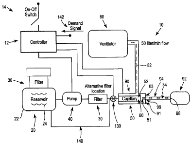
The humidification system 10 illustrated in FIG. 1 overcomes aforementioned
deficiencies of the prior art. As shown in FIG. 1, the respiratory
humidification system 10
5 includes a controller 12 having an on/off switch 14, a liquid supply 20.,
a filter assembly (or
filter) 30, a pumping unit 40, a capillary unit 50 having a heated capillary
passage 52 (i.e.,
capillary), and a ventilator 80 adapted to deliver an air stream 82.
The liquid supply 20 includes a reservoir 22 containing a suitable fluid or
liquid material
(e.g., water) 24 in liquid phase, which is capable of being volatilized within
the heated capillary
passage 52. In one preferred embodiment, the liquid supply 20 delivers water
(H20); however,
other suitable liquid materials can be used. The water 24 is supplied to the
capillary unit 50 via
the pumping unit 40. The pumping unit 40 preferably delivers the water 24 to
the capillary
unit 50 at a constant flow rate ranging from about 0.25 cc/min to about 2.2
cc/min. If desired,
the water 24 can be stored within the reservoir 22 at a pressure above
atmospheric to facilitate
delivery of the water 24 to the fluid or capillary passage 52.
In one embodiment, the water 24 is contained within a refillable storage
chamber or
reservoir 22 formed of a material suitable for containing the water 24 to be
volatilized.
Alternatively, the water 24 is contained within a disposable storage chamber
or reservoir 22
(such as a bag of sterilized and/or distilled water), which, upon exhaustion
of water 24, is
5o discarded and replaced by a new storage chamber or reservoir 22.
As shown in FIG. 1, the system 10 also includes a filter assembly 30, which is
adapted
to remove minerals from the water 24. It can be appreciated that the presence
of mineral
deposits in water supplies, including pressurized water lines can inhibit heat
transfer within the
capillary passage 52, which can lead to poor performance of the system 10. In
addition, typical
55 tap water will often leave mineral deposits within the capillary passage
52, (e.g., a capillary
tube 60 within the capillary unit 50), which can lead to an occlusion of the
capillary passage 52.
=
CA 02702993 2010-04-19
WO 2009/049909
PCT/EP2008/008860
4
The filter assembly 30 can be located either upstream or downstream of the
pumping
unit 40 depending on the pressure drop introduced by the filter assembly 30.
In a preferred
embodiment, the filter or filter assembly 30 is placed on the upstream side of
the pumping
unit 40, such that the water 24 is filtered before the pumping unit 40 pumps
the water 24 to the
capillary unit 50. In one embodiment, the filter assembly or filter 30 is an
ion-exchange resin
filter, which removes the mineral deposits from the water 24.
The pumping unit 40 receives the water 24 from the reservoir 22 and pumps the
water 24 to the heated capillary passage 52 (or fluid passage) within the
capillary unit 50,
wherein the water 24 is at least partially vaporized into an aerosol stream
83. The pumping
lo unit 40 can be any suitable pumping device, which can supply adequate
pressure and positive
metering to the capillary unit 50, such as a peristaltic pump, a gear pump, or
a piston pump. In
accordance with one embodiment, a peristaltic pump is preferred since the
wetted path is
comprised of replaceable tubing.
In accordance with one embodiment, the pumping unit 40 delivers pressurized
water 24
at approximately 10 to 80 psig (pound-force per square inch gauge) at a
constant flow, rate
ranging from about 0.25cm3/min to 2.2cm3/min (cubic centimeter per minute) to
the heated
capillary passage 52. The ventilator 80 preferably delivers an air stream 82,
which is combined
with the aerosol stream 83 from the capillary passage 52 to form a humidified
air stream 84.
The humidified air stream (or humidified gas stream) 84 is then discharged
through a patient
interface device 92.
In accordance with an embodiment, the capillary unit 50 within the system 10
generates
an aerosol stream 83 of water droplets having a particle size of less than 10
microns and more
preferably with a particle size of approximately 1 to 2 microns, which is
entrained with the air
stream 82 (e.g., up to 50 liters/minute) of the ventilator 80. The water
droplets within the
aerosol stream 83 evaporate within the air stream 82 so as to establish a
humidified air
stream 84. In accordance with one embodiment, the aerosol stream 83 from the
capillary
passage 52 is directed in a coaxial relation with respect to the air stream 82
from the
ventilator 80.
It can be appreciated that a system 10 as shown in FIG. 1 has a high air flow
rate (e.g.,
up to 50 liters per minute), which capacity assists in the evaporation of
aerosol particles 51
produced by the capillary unit 50. Consequently, a humidification system 10
has very little
condensation over long operating times. In addition, the low condensation rate
also provides
the system 10 with design flexibility in regards to the placement of the
capillary unit 50 within the
system. For example, if desired the capillary unit 50 can be in close
proximity to a patient or
alternatively incorporated in the main body of a base unit 200 (FIGS. 6-8)
containing the
pumping unit 40 and support electronics, including the control circuit 240
(FIG. 7).
CA 02702993 2010-04-19
WO 2009/049909
PCT/EP2008/008860
The capillary unit 50 includes a heated fluidic path or capillary passage 52
capable of at
least partially vaporizing the water 24. In accordance with one embodiment,
the capillary unit 50
includes a capillary tube 60 having an inlet end 54, an outlet end 56, and a
heating system 58
(FIGS. 4A and 4B). The heating system 58 can be a pair of electrodes (or
contacts) 72, 74
5 comprised of at least one upstream electrode 72 and one downstream
electrode 74 connected
to the capillary tube 60 by known means such as brazing or welding.
In accordance with one embodiment, the water 24 flows through the capillary
tube 60
into a heated section 73 (FIGS. 4A and 4B) between the pair of electrodes 72,
74, wherein the
fluid is heated and converted to a vapor or aerosol stream 83. The aerosol
stream 83 passes
io from the heated section 73 of the capillary tube 60 to the end of
the capillary tube 60 and exits
from the outlet end 56 of the capillary tube 60. The volatilized fluid in the
form of an aerosol
stream 83 exits from the capillary tube 60 and is combined with the air stream
82 from the
ventilator 80 forming a humidified air stream 84, which is discharged for
purposes such as
maintaining humidity levels in a closed space or delivery to a patient, animal
or plant.
The capillary unit 50 can be contained within a housing 90 that interfaces
with the air
stream 82 from the ventilator 80. In accordance with one embodiment, the air
stream 82 is
preferably delivered at approximately 10 liters/minute to 70 liters/minute
(LPM), and more
preferably about 5 litres/minute to 50 liters/minute (LPM). To control the
delivery of the
breathing gas or air stream 82 to the patient, the ventilator 80 can include
at least one
selectable ventilator setting control operatively connected to a processing
system for governing
the supply of ventilation support or air stream 82 to the patient.
The system 10 also preferably includes a CPAP adaptor or other suitable
patient
interface device 92 for purposes such as maintaining humidity levels in a
closed space or
delivery to a patient, animal or plant. It can be appreciated that the air
stream 82 may be from a
hospital-compressed airline or pressurized air source, such as a tank of
compressed air with a
suitable valve arrangement to achieve,a desired airflow. In accordance with
one embodiment,
the respiratory tube or flow tube 94 has an inlet 96 in communication with an
outlet 91 of the
housing 90. The respiratory tube or flow tube 94 also has an outlet 98, which
is connected to
the patient interface device 92. It can be appreciated that the respiratory
tube or flow tube 94
preferably has a length of approximately 2 to 6 feet extending from the
housing 90 to the CPAP
adaptor, nasal prongs, mask, mouthpiece or other suitable patient interface
device 92.
A programmable automation controller (not shown) preferably controls the
pumping
unit 40, as well as the heating of the capillary unit 50 including the
capillary passage 52. The
controller can be any suitable microprocessor or programmable automation
controller (PAC),
such as the CompactRIO sold by National Instruments. In accordance with one
embodiment,
the controlling of the system 10 including the algorithm to control the power
to the
electrodes 72, 74 (FIGS. 4A and 4B) can be based on the monitoring of the
resistance or
CA 02702993 2015-08-17
6
temperature of the capillary passage 52, such as disclosed in US 6 640 050 and
US 6 772 757.
In use, the system 10 is responsive to changes in relative humidity (RH) as a
result of
the low mass of the capillary unit 50 including the capillary passage 52 and
the small mass of
water 24 (i.e., pressurized water) being heated. In addition, the ability of
the pumping unit 40 to
change or adjust the flow rate of water 24 to the capillary unit 50 provides
the system 10 with
the ability to shift or change the relatively humidity (RH) of the humidified
gas stream 84 within
milliseconds. Thus, by measuring the patient's airflow, the system 10 can
deliver a humidified
gas stream 84 with a desired relative humidity by simply changing the liquid
material's 24 (i.e.,
io water) flow rate from the pumping unit 40. Additionally, the system 10
allows for the starting
and stopping of the system 10 within milliseconds, creating a system 10 that
is responsive to the
breathing profile of the patient. Accordingly, in one embodiment, the flow
rate of the water 24 to
the capillary passage 52 can be an intermittent or pulse delivery to coincide
with the breathing
profile of the patient. The low condensation rate of the humidification system
10 also affords
design flexibility in the placement of the capillary unit 50 within the system
10. For example, the
capillary unit 50 can be placed in close proximity to the patient, or
alternatively incorporated in a
separate unit containing the pumping unit 40 and support electronics and
components.
Referring to FIG. 1, in accordance with another embodiment, the system 10
preferably
includes a valve 130 (e.g. solenoid) located upstream of the capillary unit
50, a controller 12
programmed to maintain the capillary passage 52 in a heated condition at a
preferred operating
temperature and a water recirculation arrangement (or recirculation passage)
140, which in
cooperation with the valve 130 permits the pumping unit 40 to remain in a
continuously running
condition. It can be appreciated that with such arrangement, when the
controller 12 receives a
demand signal 142 from the control electronics 200 (FIG. 6), the system 10
immediately delivers
water to the heated capillary 52, which being already heated, immediately
creates and
discharges an aerosol of water vapor within a minimal response time.
Alternatively, when the
system 10 is turned off via an on-off switch 14, the heater (not shown) to the
capillary 52 and
the pumping unit 40 are shut down and the valve 130 remains closed.
It can be appreciated that the system 10 can be occasionally and/or
accidentally
operated with tap water having a mineral content that could clog the capillary
passage 52.
Accordingly, in accordance with a further embodiment, a reduction of mineral
deposits along an
interior surface of the capillary passage 52 can be obtained by coating the
interior surfaces of
the capillary passage 52 with a fluorine-containing polymer such as Teflon or
a similar
substance, and reducing the operating temperature of the heated capillary
passage 52 to
approximately 120 C to 130 C. In addition, by reducing the operating
temperature of the heated
capillary passage 52, a reduced vapor region within the capillary passage 52
is formed, thereby
reducing the opportunity for minerals to deposit therein. For example, in
accordance with a
CA 02702993 2010-04-19
WO 2009/049909
PCT/EP2008/008860
7
preferred embodiment, the Teflon coating is sufficient to reduce adhesion of
mineral deposits
along the interior surfaces of the capillary or capillary passage 52.
In accordance with another embodiment, the discharge of the capillary passage
52 is
preferably co-directional or more preferably, co-axial with respect to the
direction of the flow
stream of the ventilator 80 with which it is mixed, and wherein by such
arrangement, losses
through impaction are minimized.
FIG. 2 shows a cross-sectional view of a housing 90, which includes a heated
capillary
unit 50 in the form of a capillary tube (or passage) 60 in accordance with one
embodiment. As
shown in FIG. 2, the capillary unit 50 includes a capillary tube 60 having a
fluidic path or
capillary passage 52 with an inlet 54 and an outlet 56 (or exit end). The
inlet 54 receives the
water 24 preferably in the form of pressurized water from the pumping unit 40
with an upstream
filter system 30, or from the pumping unit 40 with a downstream filter system
30. The water 24
enters the inlet 54 of the capillary tube 60 in the form of a liquid or fluid.
In accordance with one
embodiment, the water 24 will be at least partially vaporized within the
capillary passage 52 into
an aerosol stream 83 and exits the capillary passage 52 at the outlet or exit
end 56 of the
capillary passage 52. The aerosol stream 83 from the capillary tube 60
interfaces with the air
stream 82 from the ventilator 80 at the exit end 56 of the capillary passage
52 forming a
humidified air stream 84.
The capillary tube 60 can be comprised of a metallic or non-metallic tube,
including such
materials as stainless steel, a nickel-based super alloy such as Inconel, or
glass. Alternatively,
the capillary assembly or tube 60 may be comprised of, for example, fused
silica or aluminum
silicate ceramic, or other substantially non-reactive materials capable of
withstanding repeated
heating cycles and generated pressures and having suitable heat conduction
properties.
FIG. 3 shows a cross-sectional view of the housing 90 and the capillary unit
50 of FIG. 2
along the line 3-3. As shown in FIG. 3, the aerosol stream 83 from the
capillary tube 60 is
preferably coaxial or centered within the air stream 82 from the ventilator 80
as the aerosol
stream 83 exits from the capillary tube 60 within the housing 90. In
accordance with one
embodiment, the capillary or capillary tube 60 is preferably a metallic or
stainless steel tube
having an inner diameter 62 of approximately 0.05mm to 0.5mm (0.0020 to 0.020
inches) and
more preferably an inner diameter 62 of approximately 0.2mm to 0.5mm (0.0080
inches to
0.020 inches), and an outer diameter 64 of approximately 0.1mm to 0.8mm (0.005
to
0.032 inches), and more preferably an outer diameter 64 of approximately 0.3mm
to 0.8mm
(0.012 inches to 0.032 inches).
FIG. 4A shows a side view of a heated capillary tube 60 and a heating system
(or
heater) 58 according to one embodiment. As shown in FIG. 4A, the heating
system 58 includes
an electrode assembly comprised of a pair of electrodes (or contacts) 72, 74,
which are applied
to the capillary tube 60 to provide a resistive path that connects to a
controlled power supply
CA 02702993 2015-08-17
8
(not shown). The electrodes 72, 74 are preferably located at the inlet end 54
of the capillary
tube 60 and the exit end 56 of the capillary tube 60 forming a heated section
73 between the
two electrodes 72, 74. A voltage applied between the two electrodes 72, 74
generates heat in
the heated section 73 based on the resistivity of the stainless steel or other
material making up
the capillary tube 60 or heating elements or heater, and other parameters such
as the cross-
sectional area and length of the heated section 73. The power applied between
the two
electrodes 72, 74 can be between about 1 to 70 watts, and more preferably 5W
to 50W (Watts).
The heated section 73 preferably has a heated length 66 of about 25mm (0.98
inches) to
75mm (2.95 inches), and more preferably a heated length 66 of about 25mm (0.98
inches) to
35mm (1.38 inches). In a preferred embodiment, the capillary tube 60 does not
include a tipped
capillary having a reduced diameter at the exit end 56 of the capillary tube
60.
FIG. 4B shows a side view of a heated capillary tube 60 and a heating system
58 in
accordance with another embodiment. As shown in FIG. 4B, the heating system 58
includes an
electrode assembly comprised of a pair of electrodes (or contacts) 72, 74,
which are applied to
the capillary tube 60 to provide a resistive path that connects to a
controlled power supply (not
shown). The electrodes 72, 74 are connected at spaced positions along the
length of the
capillary tube 60, with a feed (or proximal) section 71 being defined between
the inlet end 54 of
the capillary tube 60 and the upstream electrode 72, a heated section 73 being
defined between
the two electrodes 72, 74, and a distal (or tip) section 75 between the
downstream electrode 74
and the exit end 56 of the capillary tube 60. A voltage applied between the
two
electrodes 72, 74 generates heat in the heated section 73 based on the
resistivity of the
stainless steel or other material making up the capillary tube 60 or heating
system 70, and other
parameters such as the cross-sectional area and length 66 of the heated
section 73.
FIG. 5 shows a side view of a capillary unit 50 in the form of a laminate or
laminar
structure 100. In accordance with this embodiment, the capillary unit 50 is
comprised of a
laminar structure, wherein, several layers of material are bonded together to
create the fluidic
path or capillary passage 52. As shown in FIG. 5, the capillary unit 50 can be
made from a
laminate structure 100, wherein the fluidic or capillary passage 52 comprises
a channel 110 in a
first layer 102 and a second layer 104 overlying the first layer 102 encloses
the channel 110 as
described in commonly owned U.S. Patent Nos. 6,701,921 and 6,804,458.
As shown in FIGS. 6 and 7, the liquid supply 20, the filter assembly 30, the
pumping
unit 40 and the capillary unit 50 are preferably self-contained within a base
unit 200. The base
unit 200 also includes a humidity control system 210, a power source 220
preferably in the form
of a low voltage DC source (a direct current or continuous current source),
such as a wall
transformer, an outlet 230 to the ventilator circuit 85, and an electronic
control circuit 240. The
humidity control system 210 includes a humidity detector or sensor (not shown)
and a humidity
CA 02702993 2010-04-19
WO 2009/049909
PCT/EP2008/008860
9
display 214 located on an exterior surface of the base unit 200. The humidity
control
system 210 is configured such the speed of the pumping unit 40 can be altered
or changed to
provide the humidified gas stream 84 with the desired relative humidity (RH).
The electronic control system 240 controls the speed of the pumping unit 40
and power
to the electrodes attached to the capillary unit 50. In accordance with one
embodiment, an
algorithm to control power can be based on monitoring resistance or
temperature of the capillary
unit 50. It can be appreciated that by changing the speed of the pumping unit
40, which alters
or changes the liquid material's 24 (i.e., water) flow rate, a shift in the
relative humidity (RH) of
the humidified air stream 84 can be achieved within milliseconds. In addition,
by measuring
o patient airflow (or other demand for humidified air), the relative
humidity within the system 10
can be controlled, such that the relative humidity can remain constant by
responsively changing
the flow rate of the water 24 to the capillary unit 50. Accordingly, the rate
of humidification may
be varied almost instantaneously in response to changes in flow rate of air
from the ventilator.
The base unit 200 also includes an outlet 230 from the capillary unit 50 to
the ventilator
circuit 85 comprised of a ventilator supply tube 86 and an aerosol supply tube
88. The ventilator
supply tube 86 and the aerosol supply tube 88 preferably have a connection
wherein the
aerosol stream 83 from the capillary unit 50 is entrained in the air stream 82
from the
ventilator 80. It can be appreciated that any aerosols 81 associated with the
aerosol stream 83
evaporate in the air stream 82 when the air stream 82 and the aerosol stream
83 are combined
to form the humidified gas stream 84.
The filter assembly 30 as shown in FIG. 8 is preferably connected to the
pumping unit 40
with a check valve 32, which allows for the removal of the liquid supply 20
from the base
unit 200. In use, the reservoir 22 containing a liquid supply 20 is preferably
a replaceable unit,
wherein a new source of water or other suitable water 24 can be supplied as
needed.
FIGS. 9-11 show relationships for power, water flow rate and pressure for
three capillary
geometries. As shown in FIG. 9, the table shows the flow rate versus power for
a capillary
unit 50 comprised of a K32EG inner diameter capillary passage 52 having an
inner diameter of
about 0.0073 inches and a length of about 1.3 inches. FIGS. 10 and 11 show the
same
relationships for a capillary unit 50 having an inner diameter of about 1.2mm
(0.0048 inches
(32 Gauge)) and a length of about 33mm (1.3 inches), and a capillary unit 50
having an inner
diameter of about 0.19mm (0.0073 inches (K32EG)), a length of about 33mm (1.3
inches) and
an orifice of about 0.08mm (0.00314 inches), respectively.
FIG. 12 shows the relative humidity produced by the system 10 as illustrated
in FIG. 1
using a capillary unit 50 having an inner diameter of about 0.08mm (0.0073
inches) and a length
of about 33mm (1.3 inches). The measurements of relative humidity (RH) were
taken at the end
of a three foot respiratory tube, which would correspond with approximately
the location where
the patient would interface with the system 10.
CA 02702993 2010-04-19
WO 2009/049909
PCT/EP2008/008860
FIG. 13 is a table showing the particle size of an aerosol exiting a capillary
passage
(measured 25mm (1 inch) from the capillary) versus power. As shown in FIG. 13
as the amount
of power supplied to the capillary increases due to the temperature increase
the particle size of
the aerosol decreases.
5 In accordance with another embodiment, it can be appreciated that
microbial activity can
be rendered harmless. For example, a capillary passage 52 having an inner
diameter of about
0.2mm (0.008 inches) being fed 1.65cm3/minute of water, which is heated to
approximately
150*C can provide aerosolized water, which has been rendered without microbial
activity.
While various embodiments have been described, it is to be understood that
variations
o and modifications may be resorted to as will be apparent to those
skilled in the art. Such
variations and modifications are to be considered within the purview and scope
of the claims
appended hereto.