Note: Descriptions are shown in the official language in which they were submitted.
CA 02704193 2010-05-21
-1-
METHOD AND APPARATUS FOR TIPPING SUTURES
BACKGROUND OF THE INVENTION
This application is a di,yisioni4l application of
copending Canadian Application No. 2,402,690 , filed October 17,
1991.
1. Field of the Invention
This invention relates to a tipped surgical suture
and a method and apparatus for making same and a combined
tipped suture and surgical needle. In particular, it relates
to a cyanoacrylate tipping agent for braided sutures to prevent
brooming and to increase stiffness, thereby facilitating
attachment of the suture to a surgical needle.
2. Background of the Art
For many years, surgeons have employed needle-suture
combinations in which a suture or ligature is attached to the
shank end of a needle. Such needle-suture combinations are
provided for a wide variety of monofilament and braided suture
materials, both absorbable and non-absorbable, e.g., catgut,
silk, nylon, polyester, polypropylene, linen, cotton, and
absorbable synthetic materials such as polymers and copolymers
of glycolic and lactic acid.
Needle-suture combinations fall into two general
classes: standard, or non-detachable, needle attachment and
removable, or detachable, needle attachment. In the case of
standard needle attachment, the suture is securely attached to
the needle and is not intended to be separable therefrom,
except by cutting or severing the suture. Removable needle
attachment, by contrast, is such that the needle is separable
from the suture in response to a force exerted by the surgeon.
Minimum acceptable forces required to separate a needle from
a suture (for various suture sizes) are set forth in the United
States Pharmacopoeia (USP). As to
CA 02704193 2010-05-21
-2-
1 detachable needles, the United States Pharmacopoeia
prescribes minimum individual pull-out forces and minimum
average pull-out forces as measured for five needle-suture
combinations. The minimum pull-out forces for both standard
and removable needle-sutui-e.attachment set forth in the
United States Pharmacopoeia.
One typical method for securing a suture to a
needle involves providing a cylindrical recess in the shank
end of a needle and securing a suture therein. For example,
U.S. Patent No. 1,558,037 teaches the addition of a cement
material to such a substantially cylindrical recess to
secure the suture therein. Additional methods for bonding a
suture within a needle bore are described in U.S. Patent
Nos. 2,928,395 (adhesives) and 3,394,704 (bonding agents).
Alternatively, a suture may be secured within an axial bore
in a needle by swaging the needle in the region of the
recess. See, e.g., U.S. Patent No. 1,250,114. Additional
prior art methods for securing a suture within a needle bore
include expansion of a catgut suture through the application
of heat (U.S. Patent No. 1,665,216), inclusion of protruding
teeth within the axial bore to grasp an inserted suture
(U.S. Patent No. 1,678,361) and knotting the end of the
suture to be inserted within the bore to secure the suture
therein (U.S. Patent No. 1,757,129).
Methods for detachably securing a suture to a
needle are also well known. For example, U.S. Patent Nos.
3,890,975 and 3,980,177 teach swaging a suture within a
needle bore such that the suture has a pull-out value of 3
to 26 ounces. Alternative detachable attachment methods
include providing a weakened suture segment (U.S. Patent No.
CA 02704193 2010-05-21
-3-
1 3,949,756), lubricant tipping the end of a suture to be
inserted in the axial bore of a needle (U.S. Patent No.
3,963,031) and pre-tensioning a suture that is swaged within
an axial needle bore (U.S. Patent No. 3,875,946). See also,
U.S. Patent Nos. 3,799,169; 3,880,167; 3,924,630; 3,926,194;
3,943,933; 3,981,307; 4,124,027; and, 4,127,133.
Another method for attaching a suture to a needle
involves the use of tubing which is secured to the shank end
of the needle and to the suture. For example, U.S. Patent
No. 1,613,206 describes the use of a tubing (preferably
silver) which is secured to the shank end of a needle and to
a ligature. It is suggested that the tube may be attached
to the needle by pressure or soldering and to the ligature
by pressure or cementing. It is also suggested that the
shank of the needle be of reduced cross section and that the
furthest extremity of the reduced diameter shank section be
provided with a spike or point upon which the suture may be
secured prior to tube application.
U.S. Patent No. 2,240,330 describes a tubing
attachment method whereby the tubing and suture are
releasably secured to the needle. In particular, the needle
and tubing are provided with cooperating catch and abutment
means which are released one form the other by rotating the
needle 900 relative to the tubing (or vice versa). The
tubing is manufactured from spring-tempered carbon steel or
chrome nickel steel and is secured to the suture by heating
the tubing and then swaging to the suture.
U.S. Patent No. 3,311,100 related to a flexible
composite suture having a tandem linkage. The needle is
secured to a flexible suture leader manufactured from a
readily sterilizable plastic such as nylon, linear
CA 02704193 2010-05-21
-4-
1 polyethylene, isostatic polypropylene, polyester, silk or
other proteinaceous material, e.g., by inserting and
crimping the leader within an axial bore in the needle
shank. The opposite end of the suture leader is crimped
within a connector sleeve of a thin walled metal tubing,
e.g., stainless steel. The opposite end of the tubing is
crimped around a steel suture, e.g., monofilament stainless
steel.
U.S. Patent No. 3,918,455 describes a needle-
suture attachment wherein a hollow suture portion is secured
to the shank end of a needle which is of reduced cross-
section as compared to the remainder of the needle.
Additional patents which describe the use of
tubing to effect suture-needle attachment include U.S.
Patent Nos. 4,672,734 (forming needle from U-shaped metal
plate around suture), 4,359,053 (silicone tubing), 3,835,912
(laser welding of metal tube to needle), 2,814,296,
2,802,468 (chamfered tubing ends), 2,302,986, 2,240,330,
1,981,651 (needle and tubing screw threaded), 1,960,117, and
1,591,021.
In addition to the needle-suture constructions of
the aforedescribed pull-out variety, it is known from U.S.
Patent No. 4,805,292 to provide a needle-suture combination
in which a suture cutting edge is formed at the shank end of
the needle. However, the combined needle-suture device of
U.S. Patent No. 4,805,292, like others described above,
possesses asuture tip-receiving axial bore, or recess,
formed in the butt end of the needle and as such is subject
to the disadvantages recounted above which are associated
with a needle possessing an axial bore.
Insertion of sutures into a hole, recess or tube
CA 02704193 2010-05-21
-5-
1 for attachment to surgical needles presents problems
peculiar to suture needle combinations. Braided
multifilament sutures in particular are difficult to insert
into the very small aperture of a surgical needle: unless
modified, they are too limp for the suture tip to be
controlled for insertion and they have a tendency to
"broom", i.e., the filaments have a tendency to flare out at
the cut end so that the diameter of the cut end exceeds the
diameter of the needle hole. Various techniques have been
employed to modify sutures to overcome the problems of
limpness and brooming. One known method employs a tipping
agent, which is a material used to coat the suture to
stiffen the filaments and adhere them together.
Typically, a suture to he tipped is first placed
under tension to reduce slack so that the suture may be
maintained in a predetermined position on a frame or rack or
other suture holding device. Optionally, the tension may be
such as to reduce the diameter of the suture. See Canadian
Patent No. 1,009,532. The suture is then dipped into the
tipping solution and allowed to dry while under tension.
The sutures are then dried, such as by being warmed in a
drying oven at about 225 F for about 10 minutes. After
drying the sutures can be cut and released from tension.
The process results in a tipped end on each side of a cut.
Where tension has optionally been employed to reduce the
suture diameter, release of said tension will allow the
suture to expand to its original diameter except at the
tipped end portion. This can facilitate insertion of the
end into a needle.
Tipping agents may be dissolved in solvents to
form dipping solutions. By way of example, Mariotte mixture
CA 02704193 2010-05-21
-6-
1 is a dipping solution comprising nylon dissolved in
isopropyl alcohol. Other polymers and solvents may also be
used. Gould mixture is a dipping solution comprising nylon
dissolved in methanol. At least one major manufacturer of
surgical needles recommends use of Mariotte mixture or Gould
mixture for tipping sutures. A multitude of other tipping
agents, including polymers and solvents, have been proposed.
For example McGregor U.S. Patent No. 3,890,975 discloses
coating the suture with a binding resin or adhesive. The
composition may be any non-toxic adhesive composition,
either organic, inorganic or a hybrid. Suitable organic
materials are such natural products as starch, dextrin,
asphalt, animal and vegetable proteins, natural rubber,
shellac, semi-synthetic products such as cellulose nitrate
and the other cellulosics, polyamides derived from dimer
acids, castor-oil based polyurethanes; such well-known
synthetic resins Ds ':-inyl-tvnc .ac'- iticn polymers, both
resins and e].astomers; polyvinyl acetate, polyvinyl alcohol,
acrylics, unsaturated polyesters, butadiene/acrylonitrile,
butadiene/styrene, neoprene, butyl rubber, polyisobutylene;
,
and polymers formed by condensation and other step-wise
mechanisms, i.e., epoxies, polyurethanes, polysulfide
rubbers, and the reaction products of formaldehyde with
phenol, resorcinol, urea, and melamine. McGregor states
that particularly preferred bonding compositions are epoxide
resins and polyester resins.
Schmitt U.S. Patent No. 3,736,646 discloses that
it is known to tip braided sutures by dipping the end of the
suture in a plastic such as a solution in isopropyl alcohol.
Schmitt suggests that for absorbable sutures an absorbable
tipping agent is desirable, and proposes that 'a copolymer of
CA 02704193 2010-05-21
-7-
1 lactic and glycolic acid dissolved in a suitable organic
solvent, such as xylene or toluene, be applied to tip the
suture.
Nichols U.S. Patent No. 2,734,506 discloses a
dipping solution of polymers of methacrylic acid esters in
an organic solvent such as toluene, xylene acetone, ethyl
acetate, methylethyl ketone, or naphtha.
Shepherd et al. U.S. Patent No. 3,849,185
discloses the use of an acrylic casting syrup as a tipping
agent, the syrup being fully polymerized after being applied
to the suture.
In addition, paraffin/hexane solution (l00
paraffin) has been used as a suture coating agent as well as
Arrochem (TM), a nylon resin plus methanol composition
manufactured by ArroChem, Inc. of 201 Westland Farm Road,
Mt. Holly, NC 28120, and SILASTIC (TM) Medical Adhesive (a
silicon elastomer composition manufactured by Dow Corning
Co.
Although dipped sutures prepared in accordance
with the above procedures may have been used successfully,
there are several drawbacks with the use of tipping
solutions. The main problems relate to tipping consistency
and process control. Non-uniform solvent evaporation, which
may be caused by variations in the solvent, oven temperature
and heating time can result in inconsistent tipping.
Furthermore, the dried residue of polymer left after
evaporation can flake off or develop cracks.
Another method which has been employed for
treating sutures involves melt fusion, as described in U.S.
Patent No. 4,832,025, issued to Coates. The suture is
heated to a temperature at least high enough to "melt fuse"
CA 02704193 2010-05-21
-8-
1 a portion of the outer filaments of the suture. According
to Coates, such temperature is typically about 260 C to
300 C (500 F to 572 F). Exposure of synthetic sutures to
such extreme temperatures melt fuses the filaments, and the
melt fused suture portion stiffens upon cooling. Melting of
the filaments has the effect of holding the filaments
together when the suture is cut. It also causes stiffening
of the suture which facilitates insertion of the suture end
into the drilled hole of a needle. However, the melt fusion
of suture has significant drawbacks.
Firstly, the melt fusion of filaments weakens the
suture, whose tensile strength is degraded in proportion to
the extent of melt fusion.
Secondly, melt fusion causes an irreversible
change in the filaments which result in permanent stiffening
and permanent loss of tensile strength.
Thirdly, with the extre;ne temperatures disclosed
by Coates for melt fusion an inconveniently short heating
cycle is required. For example, for a size 3/0 silicone
coated polyester suture heated to between 260 C to 300 C in
a 4 mm. diameter heating tunnel, the heating time is no more
than about 3 seconds. Such short heating times make it
difficult to control the process and leads to
inconsistencies and variations in the melt fused tipping
process.
A further consideration pertinent to suture
tipping is that sutures are often prepared with lubricant
coatings such as silicone or fatty acid salts in order to
increase lubricity and to improve "tie-down" performance,
i.e., the ease of sliding a knot down the suture into place.
Such lubricant coatings typically are incompatible with the
CA 02704193 2010-05-21
- 9 -
materials and methods currently employed for tipping
sutures. In particular, prior known tipping agents do not
adhere well to lubricant coated sutures, which may result
in inconsistent tipping or an undesirable reduction of
suture-needle pull out force. The melt fusing method of
tipping may destroy the lubricant coating or render it less
effective in areas away from the needle.
A method of and apparatus for tipping surgical
sutures has been discovered which may be used to tip both
uncoated and coated sutures and which provides superior
stiffening of the suture for insertion into an opening to
attach the suture to a needle.
SUMMARY OF THE INVENTION
A surgical suture tipped with cyanoacrylate and a
process for tipping with cyanoacrylate are disclosed. in
addition, a method and apparatus are provided herein for
handling and tipping a surgical suture.
In accordance with one embodiment of the present
invention there is provided an improved suture tipping
apparatus comprising in combination a substantially
cylindrical drum having at least one longitudinal notch
extending along at least a portion of the circumference of
said drum adapted to delimit a portion of a length of
suture material on the drum to be tipped, and atomizing
means adapted to contact the delimited portion of the
suture material with a tipping agent.
In accordance with another embodiment of the
present invention there is provided an improved suture
tipping apparatus comprising a substantially cylindrical
drum having at least one longitudinal notch extending
CA 02704193 2010-05-21
- 9a -
along at least a portion of the circumference of said drum
adapted to delimit a portion of a length of suture material
on the drum and wherein the drum is made having a
circumferential surface of a high density plastic material.
Another embodiment of the present invention
provides a suture tipping apparatus comprising: a supply of
tipping agent; means for atomizing the tipping agent to
form. a mist of tipping agent; and means for contacting at
least a portion of a suture material with the mist of
tipping agent to tip the suture material with the tipping
agent.
A further embodiment of the present invention
provides a suture tipping apparatus comprising: a supply of
tipping agent; atomizing means connected to the supply of
tipping agent for atomizing the tipping agent to form a
mist of tipping agent; a drum for holding a length of
suture material and delimiting a portion of the suture
material to be tipped; and transport means supporting the
drum and synchronized with the atomizing means to contact
the delimited portion of the suture material with the mist
of tipping agent created by the atomizing means to tip the
suture material with the tipping agent.
A still further embodiment of the present
invention provides a suture tipping apparatus comprising: a
supply of tipping agent; an ultrasonic atomization head to
form a mist of tipping agent; and transport means
synchronized with the ultrasonic atomization head for
holding a length of suture material and delimiting a
portion of the suture material to be tipped and contacting
the delimited portion of the suture material with the mist
CA 02704193 2010-05-21
- 9b -
of tipping agent to tip the suture material with the
tipping agent; means connected to the ultrasonic
atomization head for driving the tipping agent through the
ultrasonic atomization head to create the mist with the
delimited portion of the suture material disposed in the
path of the mist; solvent means connected to the ultrasonic
atomization head for flushing the ultrasonic atomization
head with solvent after the tipping agent has been driven
through the ultrasonic head; nozzle means adjacent to the
ultrasonic head, the nozzle means being supplied with an
inert gas to create a curtain of inert gas directed toward
the suture material for driving excess tipping agent off
the suture material, wherein the inert gas is nitrogen.
Another embodiment of the present invention
provides a suture tipping apparatus comprising: a drum
having suture material wound thereon; a supply of tipping
agent; an atomizing head connected to the supply of tipping
agent; the atomizing head forming a mist of the tipping
agent as the tipping agent is driven through the head;
means connected to the atomizing head for driving the
tipping agent through the atomizing head to form the mist;
and a movable carriage, synchronized with the means for
driving the tipping agent to move the drum so that a
portion of the suture wound on the drum passes through the
mist.
CA 02704193 2010-05-21
-10-
BRIEF DESCRIPTION OF THE DRAWINGS
Fig. 1 is a partially cutaway side view illustrating
a surgical needle and suture combination.
Fig. 2 is an exploded perspective view illustrating
a surgical needle in conjunction with a suture.
Fig. 3 is a partially cutaway side view illustrating
a surgical needle in combination with a suture.
Fig. 4 is a diagrammator illustration of the suture
winding system of the present invention.
Fig. 5 is a side elevational view of the suture
winding apparatus of the present invention.
Fig. 6 is a perspective view of the suture winding
drum of the present invention.
Fig. 6A is an end view of a rib configuration
associated with the suture winding drum.
Figs. 6B and 6C show end elevational views of drums
having 2 and 3 notches, respectively.
Fig. 7 is a side view of the suture retaining clamp
of the present invention.
Fig. 8 is a perspective view of the main support of
the suture clamp.
CA 02704193 2010-05-21
-11-
1 Fig. 9 is a perspective view of the dowel arm
support of the present invention.
Fig. 10 is a perspective view of the dowel arm of
the present invention.
Fig. 11 is a perspective view of the rocker clamp
support of the present invention.
Fig. 12 is a perspective view of the rocker clamp
of the present invention.
Fig. 13 is a perspective view of the rocker spring
of the present invention.
Fig. 14 is a perspective view of the suture
tipping apparatus of the present invention.
Fig. 15 is a cut away front elevational view of
the suture tipping apparatus of the present invention.
Fig. 16 is a cut away side elevational view of the
suture tipping apparatus of the present invention.
Fig. 17 is a front sectional view of the spray
head assembly of the suture tipping apparatus.
Fig. 18 is a partially cut away side view of the
spray head assembly of the suture tipping apparatus.
Fig. 19 is a perspective view of a suture with a
tipped portion.
Fig. 20 is a schematic illustration of the suture
tipping system of the present invention.
Fig. 21 illustrates the placement of clamps on the
drum to secure the suture for a cutting procedure.
DETAILED DESCRIPTION OF PREFERRED EMBODIMENTS
The present invention is generally directed to
tipping surgical sutures with cyanoacrylate in order to
stiffen the suture tip and, as to multifilament sutures,
prevent brooming. Tipping the suture with cyanoacrylate
CA 02704193 2010-05-21
-12-
facilitates insertion of the suture tip into an opening for
attachment to a suture. Advantageously, the cyanoacrylate
tipping is compatible with a broad range of sutures and
coatings, and a novel method and apparatus have been
developed for applying cyanoacrylate to sutures in an
atomized spray. Because the cyanoacrylate tipping agent and
process are applicable to a wide range of materials and
needle suture attachment methods, suture constructions and
general methods of tipping sutures will be discussed prior
to discussing the preferred apparatus for spray tipping.
The Suture
The present invention is primarily directed to the
treatment of braided surgical sutures. The term "braid"
means a substantially symmetrical strand formed by crossing
a number (at least three) c i;,_?ivid al strands composed of
one or more filaments di-gonally in such Danner that each
strand passes alternatively over and under one or more of
the others. The braid may be of traditional tubular braid
construction or spiroid braid construction and may include a
core section composed of one or more filaments around which
the braid is externally fabricated.
The braided suture can be fabricated from a wide
variety of natural and synthetic fibrous materials such as
any of those heretofore disclosed for the construction of
sutures. Such materials include non-absorbable as well as
partially and fully bio-absorbable (i.e., resorbable)
natural and synthetic fiber-forming polymers. Non-
absorbable materials which are suitable for fabricating
braided sutures include silk, polyamides, polyesters such as
polyethylene terephthalate, polyacrylonitrile, polyethylene,
CA 02704193 2010-05-21
-13-
1 polypropylene, silk cotton, linen, etc. Carbon fibers,
steel fibers and other biologically acceptable inorganic
fibrous materials can also be employed. Bio-absorbable
sutures may be fabricated from natural collagenous material
or synthetic resins including those derived from glycolic
acid, glycolide, lactic acid, lactide, dioxanone,
polycaprolactone, epsilon-caprolactone, trimethylene
carbonate, etc., and various combinations of these and
related monomers. Sutures prepared from resins of this type
are known in the art.
Braided multifilament sutures typically are coated
with one or more coating compositions to improve functional
properties such as surface lubricity and knot tie-down
behavior. A variety of suture coating compositions proposed
for either or both of these purposes are well known in the
art, e.g., those disclosed in U.S. Patent Nos. 3,867,190;
3,942,532; 4,047,533; 4,452,973; 4,624,256; 4,649,920;
4,716,203; and 4,826,945.
A preferred lubricant coating is a bioabsorbable
coating composition obtained by copolymerizing in accordance
with known procedures (1) a polyether glycol selected from
the group consisting of relatively low molecular weight
polyalkylene glycol, e.g., one corresponding to the general
formula HO(RO),H wherein R is an alkylene group of from 2-4
carbon atoms and y is an integer of from about 100-350, and
polyethylene oxide-polypropylene oxide block copolymer,
e.g., one corresponding to the general formula
H (OCH2CH2) x (OC3}i6) Y (OCH2CH2) ,OH wherein x is an integer of from
about 45-90, y is an integer of from about 60-85 and z is an
integer of from about 45-90 with (2) a mixture of lactide
CA 02704193 2010-05-21
-14-
monomer and glycolide monomer or a preformed copolymer of
lactide an glycolide, the weight ratio of (1) to (2)
preferably ranging from about 4:1 to about 1:4 and more
preferably from about 2:1 to about 1:2. The ratio of
lactide to glycolide in the monomer mixture or in the
copolymer of these monomers preferably varies from about 65-
90 mole percent lactide and 10-35 mole percent glycolide.
Polyether glycols having molecular weights of about 3,500-
25,000 and preferably from about 4,000-10,000 and
polyethylene oxide-polypropylene oxide block copolymers
having molecular weights of from about 4,000-10,000 and
preferably from about 7,500 to about 9,000, e.g., those
disclosed in U.S. Patent Nos. 2,674,619, 3,036,118,
4,043,344 and 4,047,533 and commercially available as they
*pluronics (BASF-Wyandotte). Where preformed copolymers of
lactide and glycolide are employed in preparing the
bioabsorbable coating compositions, they may be prepared as
described in U.S. Patent No. 4,523,591.
The amounts of bioabsorbable coating composition
to be applied to the suture, e.g., by coating, dipping,
spraying or other appropriate techniques, will vary
depending upon the specific construction of the suture, its
size and the material of its construction. In general, the
coating composition applied to an unfilled suture will
constitute from about 1.0 to about 3.0 percent by weight of
the coated suture, but the amount of coating add on may
range from'as little as about 0.5 percent, by weight, to as
much as 4.0 percent or higher. For a preferred filled (i.e.
containing a storage stabilizing agent) braided suture,
amounts of coating composition will generally vary from
about 0.50 to about 2.09. with as little as 0.2% to as much
*trade-mark
CA 02704193 2010-05-21
-15-
1 as 3.0%. As a practical matter and for reasons of economy
and general performance, it is generally preferred to apply
the minimum amount of coating composition consistent with
good surface lubricity-and/or knot tie-down characteristics
and this level of coating add on is readily determined
experimentally for any particular suture.
Recently it has been proposed to also apply to an
absorbable braided suture a storage stabilizing amount of a
filler material containing at least one water soluble liquid
polyhydroxy compound and/or ester thereof. In addition to
having an enhanced degree of storage stability, a braided
suture which has been filled with a storage stabilizing
amount of, e.g., glycerol, exhibits better flexibility and
"hand" characteristics than the untreated suture. Moreover,
since the polyhydroxy compounds are generally capable of
dissolving a variety of medico-surgically useful substances,
they can be used as vehicles to deliver such substances to a
wound or surgical site at the time the suture is introduced
into the body.
The useful storage stability agents are generally
selected from the water soluble, liquid polyhydroxy
compounds and/or esters of such compounds, preferably those
having no appreciable toxicity for the body at the levels
present. The expression "liquid polyhydroxy compound"
contemplates those polyhydroxy compounds which in the
essentially pure state are liquids, as opposed to solids, at
or about ambient temperature, e.g., at from about 15 C to
about 40 C. The preferred polyhydroxy compounds possess up
to about 12 carbon atoms and where the esters are concerned,
are preferably the monoesters and diesters. Among the
specific storage stabilizing agents which can be used with
CA 02704193 2010-05-21
-16-
1 generally good results are glycerol and its mono- and
diesters derived from low molecular weight carboxylic acids,
e.g., monoacetin and diacetin (respectively, glyceryl
monoacetate and glyceryl diacetate), ethylene glycol,
diethylene glycol, triethylene glycol, 1,3-propanediol,
trimethylolethane, trimethylolpropane, pentaerythritol,
sorbitol, and the like. Glycerol is especially preferred.
Mixtures of storage stabilizing agents, e.g., sorbitol
dissolved in glycerol, glycerol combined with monoacetin
and/or diacetin, etc., are also useful.
To prevent or minimize run-off or separation of
the storage stabilizing agent from the suture, a tendency to
which relatively low viscosity compounds such as glycerol
are especially prone, it can be advantageous to combine the
agent with a thickener. Many kinds of pharmaceutically
acceptable non-aqueous thickeners can be utilized including
water-soluble polysaccharides, e.g., hydroxypropyl
methycellulose (IIPMC), and the other materials of this type
which are disclosed in European Patent Application 0 267 015
referred to above, polysaccharide gums such as guar,
xanthan, and the like, gelatin, collagen, etc. An
especially preferred class of thickeners are the saturated
aliphatic hydroxycarboxylic acids of up to about 6 carbon
atoms and the alkali metal-and alkaline earth metal salts
and hydrates thereof. Specific examples of such compounds
include salts of lactic acid such as calcium lactate and
potassium lactate, sodium lactate, salts of glycolic acid
such as calcium glycolate, potassium glycolate and sodium
glycolate, sales of 3-hydroxy propanoic acid such as the
calcium, potassium and sodium salts thereof, salts of 3-
hydroxybutanoic acid such as calcium, potassium and sodium
CA 02704193 2010-05-21
-17-
1 salts thereof, and the like. As stated hereinabove,
hydrates of these compounds can also be used. Calcium
lactate, especially calcium lactate pentahydrate, is a
particularly preferred thickener.
When a thickener is utilized, it will be
incorporated in the filling composition in at least that
amount required to increase the overall viscosity of the
storage stabilizing agent to the point where the agent no
longer readily drains away from the suture in a relatively
short period. In the case of a preferred storage
stabilizing agent-thickener combination, namely, glycerol
and calcium lactate, the weight ratio of glycerol to calcium
lactate can vary from about 1:1 to about 10:1 and preferably
is from about 6:1 to 8:1.
If necessary or desirable, the storage stabilizing
agent together with optional thickener can be dissolved in
any suitable non-aqueous solvent or combination of solvents
prior to use. To be suitable, the solvent must (1) be
miscible with the storage stabilizing agent and optional
thickener, if present (2) have a sufficiently high vapor
pressure to be readily removed by evaporation, (3) not
appreciably. affect the integrity of the suture and (4) be
capable of wetting the surface of the suture. Applying
these criteria to a preferred storage stabilizing agent,
glycerol, advantageously in admixture with a preferred
thickener, calcium lactate, lower alcohols such as methanol
and ethanol are entirely suitable solvent carriers. When a
solvent is utilized in the preparation of the stabilizing
agent, e.g., methanol, such solvent can be employed in
amounts providing a solution concentration of from about 20%
to about 50%, preferably about 30% to about 45%, by weight
CA 02704193 2010-05-21
-18-
1 of the storage stabilizing agent including any optional
thickener.
As stated, a braided suture may be impregnated
with one or more medico-surgically useful substances, e.g.,
those which accelerate or beneficially modify the healing
process when the suture is applied to a wound or surgical
site. So, for example, the braided suture herein can be
provided with a therapeutic agent which will be deposited at
the sutured site. The therapeutic agent can be chosen for
its antimicrobial properties, capability for promoting wound
repair and/or tissue growth or for specific indications such
as thrombosis. Antimicrobial agents such as broad spectrum
antibiotics (gentamicin sulphate, erythromycin or
derivatized glycopeptides) which are slowly released into
the tissue can be applied in this manner to aid in combating
clinical and sub-clinical infections in a surgical or trauma
wound site.
To promote wound repair and/or tissue growth, one
or more biologically active materials known to achieve
either or both of these objectives can be applied to the
braided suture of the present invention. Such materials
include any of several Human Growth Factors (I-IGFs),
magainin, tissue or kidney plasminogen activator to cause
thrombosis, superoxide dismutase of scavenge tissue damaging
free radicals, tumor necrosis factor for cancer therapy,
colony stimulating factor, interferon, interleukin-2 or
other lymphokine to enhance the immune system, and so forth.
The filling composition can contain one or more
additional components which promote or enhance the wound
healing effectiveness of the HGF component. Thus, e.g.,
site-specific hybrid proteins can be incorporated in the
CA 02704193 2010-05-21
-19-
1 filling composition to maximize the availability of the HGF
at the wound site and/or to potentiate wound healing. See
e.g., Tomlinson (Ciba-Geigy Pharmaceuticals, West Sussex,
U.LK.), "Selective Delivery and Targeting of Therapeutic
Proteins", a paper presented at a symposium held June 12-14,
1989 in Boston, MA. The HCFs can also
be associated with carrier proteins (CPs),
e.g. in the form of CP-bound
HGF(s), to further enhance availability of the HGF(s) at a
wound site as disclosed in "Carrier Protein-Based Delivery
of Protein Pharmaceuticals", a paper of BioGrowth, Inc.,
Richmond, CA presented at the aforementioned symposium-
The HGFs can also be incorporated in liposomes to
provide for their release over an extended period.
Lactate ion can be present to augment the wound healing
activity of the HGF. Protectants for the HGF can also
be utilized, e.g., polyethylene glycols, acteoxyphenoxy
polyethoxy ethanols, polyoxyethylene sorbitans,
dextrans, albumin, poly-D-alanyl peptides and N-(2-
hydroxypropyl)- methacrylamide (HPMA)
Cyanoacrylate Tipping
As stated previously, prior known tipping
methodologies are not fully compatible with a suture or its
coatings, fillers, therapeutic agents, antimicrobial agents
and/or biologically active materials, either because the
tipping agent will not adhere properly or because the
methodology (such as melt fusing) results in deterioration
of the suture, its coatings, additives, and fillers.
CA 02704193 2010-05-21
-20-
1 The suture tipping agent and method of the present
invention are compatible with and may be used on any type of
surgical suture including multifilament bioabsorbable or
non-bioabsorbable sutures. Advantageously, the tipping
agent and method of the invention are applicable to all
types of multifilament braided sutures, including those
which contain one or more fillers, coatings, etc.
In practice, a segment of the suture is selected
for tipping and may be of any length appropriate for
inserting a suture end cut from such segment into an
opening, such as the barrel end of a surgical needle, to
facilitate attachment of the suture to the needle.
Typically the suture is placed under sufficient
tension to take up slack. Additional tension may be applied
to reduce the suture diameter, if desired, to result in a
tipped section of reduced diameter relative to the remainder
of the suture.
A stiffening or "tipping" agent is then applied to
the selected segment of suture. The stiffening agent is a
cyanoacrylate monomer such as methyl 2-cyanoacrylate, or
ethyl 2-cyanoacrylate. The preferred cyanoacrylate is
available under the name LOCTITE(T111) Medical Device Adhesive
18014 and is available from the Loctite Corporation, 705 N.
Mountain Road, Newington, CT 06111. The preferred Loctite
Medical Device Adhesive is a moisture activated polymer
which comprises 99+o ethyl cyanoacrylate and small amounts
of hydroquinone and organic anhydride. It has a specific
gravity of 1.05, and a boiling point greater than 300 F.
The cyanoacrylate monomer may be applied in a variety of
ways, such as dipping or brushing and
preferably is applied
by spraying, as described below. Upon contact with the
CA 02704193 2010-05-21
-21-
suture, the residual moisture of the suture and surrounding
environment catalyzes the polymerization of the
cyanoacrylate almost instantly. The polymerized
cyanoacrylate stiffens the segment of the suture by coating
the individual filaments of the suture with a relatively
stiff coating, and, because the cyanoacrylate is an
adhesive, the individual filaments are bonded together to
prevent brooming. A further advantage of the ethyl
cyanoacrylate tipping agent is that it is bioabsorbable and
will not leave a.permanent residue in body tissue. Because
the cyanoacrylate polymerizes almost instantly, the tipping
agent is stiffened immediately without any additional drying
or curing steps. This has the added advantage of reducing
processing steps and accompanying handling and equipment
requirements. In the preferred spray tipping process,
polymerization is substantially complete by the end of the
apparatus cycle and the tipped suture may be further
processed without delay.
The next step is cutting the stiffened segment to
create at least one "tipped" end for connecting to the end
of a surgical needle. Two tipped ends of the suture may be
desirable for attaching a needle to each end of the suture
to provide a so-called double armed suture. The coated
segment may be cut with scissors, a razor blade, or by a
knife edge moving transverse to the direction of the tipped
suture segment, or by any other suitable means.
Suture-Needle Attachment
The tipped end is now ready to be connected to the
surgical needle.
CA 02704193 2010-05-21
-22-
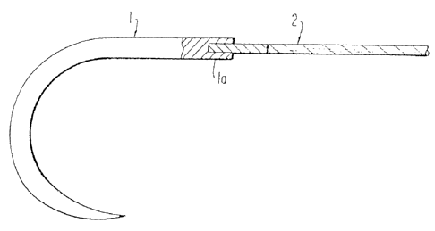
One method of connection, illustrated in Fig. 1,
requires a needle 1 with a barrel end having an axial
aperture la. The tipped end of suture 2 is inserted into
the aperture la and the end of the needle may then be
swaged, crimped or otherwise constricted to grip and hold
the suture, either permanently or with a pull-out force
defined by U.S.P. for detachable needles. The swage or
crimp method of attachment is conventional and well known in
the art.
Another method of attaching the suture to the
needle is illustrated in Fig. 2 wherein the barrel end of
the needle 1 has a cylindrical portion lb of lesser diameter
than the needle and extending axially from the needle 1.
The "tipped" or stiffened end 2a of 'suture 2 is positioned
adjacent portion lb and extends axially through the bore of
a tube 3, which is positioned around the junction of tipped
end 2a and needle portion lb. Tube 3 is made of a material
capable of shrinking or undergoing contraction upon
application of energy, e.g., heat. Suitable materials
include "memory based metals," e.g., nickel-iron-titanium
mixtures, or copper based materials, as are well known in
the art (see, e.g., U.S. Patent Nos. 3,759,552, 3,801,954,
4,198,081 and 4,733,680), and shrinkable plastic materials,
such as polyvinylidene fluoride materials available from
Raychem Corporation, Menlo Park, California, under the
tradename *Kynar. One such polyvinylidene fluoride material
available from Raychem Corporation is RT-850. In the case
of shrinkable plastic materials, the tubing typically is
extruded such that the inner diameter is less than the final
desired diameter, i.e., the inner diameter of the tubing
after energy application in the attachment method of the
*trade-mark
CA 02704193 2010-05-21
-23-
1 present invention. Thereafter, the extruded tubing is
expanded radially outward through radial expansion means to
provide a tubing or expanded inner diameter. Such plastic
tubing is thus adapted to shrink or "recover" to its
original extruded inner diameter in response to the
application of a predetermined amount of energy. Suitable
energy sources to accomplish shrinking of tubing 3 include
heat (convective or conductive), radiation, microwave
energy, etc.
Tube 3 is then subjected to energy, preferably
consisting of heat, in order to cause shrinkage or
contraction of the tube such that the inner surface of the
tube bore grips both the needle portion la and the suture
end 2a in the vicinity of the joint as shown in Fig. 3.
Alternatively, the tube may be ,attached to the needle and
suture sequentially, such as by first applying localized
energy to shrink the tube onto the needle shank and
thereafter applying energy to the remainder of the tube to
shrink the tube into the suture tip. Variations in the
needle shank, such as tapering, contouring or ribbing, may
be used to increase gripping force of the tube to the
needle. Similarly, the relative gripping force of the tube
on the needle shank and suture may be varied by varying the
length of the tube section contacting each of the needle
shank and suture. In addition, tube 3 preferably is
configured and dimensioned such that when it is contracted
the outer surface of the tube is substantially flush or even
with the outer surface of the needle. The gripping force of
the shrinkable tube 3 is sufficient to maintain the minimum
required pull out force for the suture, and may be adjusted
to provide either permanently attached or detachable suture
CA 02704193 2010-05-21
-24-
1 needles. It has been found that sutures, particularly
coated and filled sutures, tipped in accordance with the
method of the present invention have significantly higher
pull out forces.
Attempts were made to tip coated sutures, such as
silicone coated Dacron braided sutures, with polyurethane
and epoxy adhesives. These attempts did not result in any
tipped sutures suitable for attachment to needles.
Comparative Examples 1-2
Dacron polyester 1-0 braided sutures coated with
silicone were tipped by swab application of (i) Arrochem
composition; and (ii) a "hot melt" 10% paraffin/hexane
solution. Sutures tipped with the 10% paraffin/hexane were
further treated for 60 seconds in a heating apparatus set at
315 F. The 10% paraffin/hexane solution was difficult to
work with since it had to be maintained at about 130 F with
constant stirring in order to maintain the paraffin in
solution. The tipped sutures were swaged to needles in a
conventional manner and pull-out force in both cases was
measured to be about 0.05 kg.
Comparative Example 3
In an attempt to.improve on the results of
Comparative Examples 1-2, Dacron polyester 1-0 braided
sutures were placed in toluene and brought to temperature of
80-82 C for ten minutes. The total dwell time in toluene
was approximately 20 minutes. The washed sutures were
tipped with 10% paraffin/hexane by swab application and
heated to 315 F for 60 seconds. The maximum pull-off forces
were approximately 0.05 kg, showing no improvement.
CA 02704193 2010-05-21
-25-
1 Comparative Examples 4-14
Dacron polyester 1-0 braided sutures coated with
silicone were ultrasonically washed for five minutes in one
of isopropyl alcohol, TP10, *Freon TF, hexane, xylene, and
III-trichloromethane. Samples of sutures washed by each
method were tipped with Arrochem solution and 10%
paraffin/hexane (the paraffin/hexane tipped sutures were
heated to 315 F for 60 seconds, as before), resulting in
twelve types of differently treated and tipped sutures. The
tipped sutures were swaged to needles and the pull-out force
was measured. The pull-out forces of these sutures showed
some improvement, having pull-out forces of about 1.5 kg,
but still did not achieve reliably high pull-out forces.
Comparative Examples 15-16
Silicone coated Dacron@ polyester 1-0 braided
sutures were wound on a paddle and soaked for five minutes
in a 5% Mariotte mixture solution (50 grams nylon in 946 ml.
isopropyl alcohol and'.150 ml. water). Thereafter, the
sutures were heated for 60 seconds at 315 F and, after
cooling, Arrochem solution was applied over the tip
previously treated with Mariotte mixture. No improvement in
pull out force was obtained, and the extended exposure to
Mariotte mixture was observed to have detrimental effects on
the suture braid.
The above procedure was repeated using a 10 minute
soak in Mariotte mixture followed by heat treating for 10
minutes in an oven at 225 F, followed by tipping with
Arrochem composition. No improvement in pull-out force was
observed when these sutures were attached to needles.
*trade-mark
CA 02704193 2010-05-21
I =
-26-
1 Comparative Example 17
Silicone coated Dacron polyester 1-0 braided
sutures were ultrasonically washed for 5 minutes in toluene
and tipped with 10% paraffin/hexane solution by swab
application. The pull-off force net U.S.P. minimums, e.g.
.45 kg, but was still insufficient.
Comparative Examples 18-29
Silicone coated Dacron polyester 1-0 braided
sutures were ultrasonically washed for 10 minutes in a
variety of different washing solutions, tipped by soaking
for 5 minutes in'either Arrochem or 5% Mariotte mixture, and
attached to needles. The results are listed below in Table
I.
TABLE I
Pull-Off
Cleaning Solution Tipping Agent Force (kq)
18. Isopropyl alcohol Arrochem 0.05 - 1.0
19. Isopropyl alcohol Paraffin/Hexane 0.05 - 1.0
20. Freon T-F Arrochem 0.05 - 1.0
21. Freon T-F Paraffin/Hexane 0.05 - 1.0
22. Freon TP 10 Arrochem 0.05 - 1.0
23. Freon TP 10 Paraffin/Hexane 0.05 - 1.0
24. Trichioroethylene Arrochem 0.05 - 1.0
25. Trichioroethylene Paraffin/Hexane 0.05 - 1.0
26. Xylene Arrochem 0.08 - 1.3
27. Xylene Paraffin/Hexane 0.08 - 1.3
28. Hexane Arrochem 0.08 - 1.3
29. Hexane Paraffin/Hexane 0.08 - 1.3
Comparative Examples 30-33
Braided Dacron polyester size 1-0 braided sutures
were ultrasonically washed in a toluene bath for 20 minutes.
CA 02704193 2010-05-21
-27-
n
1 After solvent cleaning the sutures were tipped by soaking
for 5 minutes in one of (i) 10% Silastic Medical Adhesive in
hexane; (ii) 10% paraffin/hexane; (iii) Arrochem solution;
or (iv) Mariotte mixture. All the tipped sutures were post-
tipped at 315 F for 60 seconds. The tipped ends were cut
and inserted into surgical needles, the needles were swaged,
and the pull out forces were measured. The results are set
forth in Table II.
TABLE II
Pull-out forces for Dacron polyester 1-0 braided
sutures ultrasonically cleaned in toluene for 20 minutes.
Tipping Agent Pull-out Force kq
30. Silastic/Hexane 1.0 - 1.8
31. Paraffin/Hexane 1.0 - 1.6
32. Arrochem 1.3 - 1.8
33. Mariotte Mixture 1.8 - 2.5
From the foregoing it would appear that ultrason:.c
washing in toluene for 20 minutes prior to tipping with a
conventional agent might lead to acceptable results.
Unfortunately, however, toluene is an undesirable material
due to its toxicity and the harsh effects on the suture
material.
Examples 1-6
Samples were selected for testing of (i) size 0
braided synthetic absorbable sutures made from 90%
glycolide, 10% lactide coated with a
glycolide/lactide/polyethylene oxide mixture, and filled
with glycerin/calcium lactate; and (ii) braided nylon (non-
bioabsorbable) sutures coated with silicone lubricant.
Selected segments of the sutures were tipped with Loctite
CA 02704193 2010-05-21
-28-
1 Selected segments of the sutures were tipped with Loctite
Adhesive 18014, which was allowed to fully polymerize. The
.suture segments were cut to create tipped ends which were
then inserted into a drilled hole in the barrel end of
.5 surgical needles. The needles were then swaged by a) double
hit swaging, b) split-ring, and c) clover leaf dies, and
pull out forces for each type of attachment were measured.
The test results are set forth in Tables III, IV and V
below.
TABLE III
Cyanoacrylate-Tipped Sutures
Conventional Double-Nit Swaging
PRE-STERILIZATION POST-STERILIZATION
SUTURE SIZE PULL-OUT FORCE PULL-OUT FORCE
SAMPLES AVG. RANGE SAMPLES AVG. RANGE
Synthetic Absorbable, 0 n-5 2.6 }:Es. - n-5 2.9 kgs.
2. Braided Nylon** 0 n-10 1.8 kgs.= - n-10 1.8 kgs.
TABLE I V
~
Cyanoacrylate-Tipped .`.utures
Solis Ring Swagins
PRE-STERILIZATION POST-STERILIZATION
SUTURE SIZE PULL-OUT FORCE PULL-OUT FORCE
S?1iPLES AVC. RANGE S?1`iPLES AVG. RANGE
3- Synthetic Absorbable 0 n-15 3.2 kgs. 2.9-3.7 n-8 3.1 k;s. 2.5-3.4
kgs. kgs.
4-'Braided Nylon** 0 n-11 3.3 kgs. 1.4-7.1 n-15 2.9 kgs. 2.4-3.2
kgs. kgs..
CA 02704193 2010-05-21
-29-
TABLE V
Cyanoacrylate -Tip?ed Sutures
Clover Leaf Swaein?
PRE-STEP.ILIZ=TION POST- STERILIZ'.TION
SU71TRE SIZE PULL-OUT FORCE PULL-OUT FORCE
S?JMPL ES AVG. R_NCE SA24PLES AVG. RgNG
S-Synthetic t bsorbable* 0 n-15 3.5 kgs. 2.8-4.4 n-15 3.3 k_s. 2.5-4
kgs. kgs
6. Braided Nylon** 0 n-15 2.9 kgs. 1.5-3.9 n-15 3.2 ks. 1.9-4
kgs. kgs
* Synthetic Absorbable Sutures (90% glycolide/108 lacti.de) coat=-d with
with a glycolide/lactide/polyethylene oxide copolymer and
fillet' with glycerine/calciwn lactate mixture
kx Braided Nylon Sutures coated with silicone lubricant.
The minimum pull out force required by the U.S.
Pharmacopeia for size 0 suture is 1.5 kg Avg/0.45 kg
individual. As can be seen from Tables III, IV, and V, the
pull out forces for the cyanoacrylate tipped sutures exceeds
the minimum USP requirements.
As can be seen from a comparison of the pull-out
forces tabulated in the above examples and comparative
examples, the suture tipping method of the present invention
using cyanoacrylate tipping agent produces pull-out forces
superior to those of methods using prior known tipping
agents, particularly with respect to filled sutures and
sutures coated with lubricant coatings. Remarkably, these
results are attained without washing the suture prior to
cyanoacrylate tipping. This is surprising since the prior
known methods of using cyanoacrylates typically require the
CA 02704193 2010-05-21
-30-
1 surface to be bonded to be free of oils, mold release
agents, or other foreign matter in order to achieve maximum
bond performance.
Tipping Apparatus
The following description discloses the preferred
apparatus for spraying cyanoacrylate monomer onto the suture
by atomization.
Method For Winding A Suture
To insure consistency of the diameter at the
tipped portion of the suture, a method and apparatus have
been developed for monitoring suture ovality and adjusting
winding tension to control and, if desired, modify the
suture diameter. A diagram of the system for loading
sutures on a drum is illustrated in Fig. 4.
The pay off section includes a spool 10 on which
suture material 11 is stored. A friction tensioning device
applies drag to the outside of the spool to prevent the
spool from freewheeling. The suture is guided onto a
capstan 12 which is electronically controlled by means of
friction clutch 13 and clutch power supply 14. The suture
11 then passes onto the drum assembly 26. Power is supplied
by standard 120 volt power sources 15. When tension is
applied to the suture, the suture diameter is reduced. When
the clutch is relaxed, the diameter of suture material under
tension expands. Based on dimensional information
continuously fed to the clutch control from an x-y laser
micrometer 18, the clutch applies tension to or releases the
suture in order to maintain suture diameter within selected
parameters.
CA 02704193 2010-05-21
I
-31-
1 The x-y laser micrometer 18 continuously monitors
the diameter of the suture in the x and y directions, i.e.
suture ovality, by means of x-y heads 19 which are oriented
orthogonal to each other. The laser micrometer
electronically compares the x-y measurements with
preselected minimum and maximum dimensions pertaining to the
particular type and size of suture. This information is
employed in a negative feedback control loop whereby the
clutch tension is adjusted by means of a drive motor 17 and
potentiometer clutch controller 16. In the event either
dimension exceeds the maximum diameter for the suture size,
the clutch tension is increased in order to decrease the
diameter of the suture. In the event either dimension is
less than the minimum suture diameter the clutch tension is
relaxed until the suture diameter is increased into the
suture diameter range. The information is processed and
clutch tension adjusted within milliseconds of the actual
measurement to continuously adjust clutch tension.
Referring more specifically to the laser
micrometer, an instrument suitable for use in the present
invention is available from Zumbach Electronics Corp., 140
Kisco Avenue, Mount Kisco, N.Y. 10549 under the designation
ODAC 19M, which is a microcomputer controlled measuring
system having x-y heads which incorporate laser scanners.
Fig. 5 illustrates a side view of the suture
handling apparatus. Suture storage spool 10 is rotatably
mounted at the top of mounting frame 20. Suture 11 is drawn
off and passes through guide 21, around capstan 12 and over
and around guide roller 22. Suture 11 then passes through a
second guide member 23, through laser micrometer 18 where
the x-y measurements are made, around guide rollers 24 and
CA 02704193 2010-05-21
-32-
1 25, and finally onto drum 26. Drum 26 is mounted onto drum
mounting frame 27 and is driven to receive suture 11 and
maintain tension thereon. During winding of the suture onto
drum 26, drum mounting frame 27 traverses in the plane
perpendicular to Figure 5 so that the suture is continuously
wound around the drum in a. helix from one end of the drum to
the other with no two adjacent suture portions touching.
Figs. 6 and 7 illustrate the drum assembly 26 in
greater detail.
Referring to -Fig. 6, the drum assembly comprises a
substantially cylindrical drum 26 having a smooth
circumferential surface 31. In order to facilitate gentle
treatment of the sutures, the drum may be made of polished
stainless steel or stainless steel covered with a silicon
rubber skin. Most preferably, drum 26 is fabricated from
high density polyethylene with steel end plates. High
density polyethylene has been found to be particularly
advantageous since excess cyanoacrylate does not adhere to
this material during the tipping operation. Where the drum
is constructed of high density polyethylene it further has
been found desirable to reinforce the drum against
deformation by providing a plurality of gussets or ribs
inside the drum. An end view of one appropriate rib
configuration is shown in Fig. 6A. Each rib has a thickness
of about 4 to -, inches in the direction perpendicular to the
plane of rig. 6A. The number of ribs may vary, but two to
five ribs should be appropriate, and three ribs are
preferred. Drum 26 could also be fabricated from a solid
block of high density polyethylene, but the added weight of
such a construction most likely will not be desired.
CA 02704193 2010-05-21
1 -33-
1 Referring again to Fig. 6, a notch 32 extends
lengthwise along the drum. When suture 11 is wound around
the drum a portion of each suture wrap will extend across
the notch orthogonally to the lengthwise orientation of the
notch. The end plate 33h has central apertures 34 and an
axial spindle 29 by which the drum can be mounted to fixture
27 such that the drum can be rotated to wind suture 11
thereon. Apertures 35 and 36 are for mounting the suture
retainer clamps to hold the tipped sutures in place while
the tipped section is cut to remove the sutures from the
drum, as described below. Peripheral apertures 37 are for
attachment of the end plates to the drum, such as by screw
mounting, and aperture 33 is provided to receive a
positioning pin on the tipping apparatus to hold the drum in
the correct orientation during tipping. Of course, drums of
different circumference can be made in order to provide
tipped sutures of different lengths. By way of example
only, drums having a circumference of thirty six, thirty,
twenty four and eighteen inches are contemplated. The
cylindrical construction of the drum has the added advantage
of being conducive to providing multiple longitudinal
notches on drums of different circumference in order to be
able to tip a variety of different length sutures in a
single tipping operation. Figs. 6B and 6C show end
elevational views of drums 26B and 26C having 2 and 3
notches, 32, respectively. It is contemplated that drums
having the following general dimensions (inches) could be
provided.
35
CA 02704193 2010-05-21
-34-
1 Drum Circumference Number of Notches Tipped Suture Lengths
15 3 5
16 2 8
24 2 12
pray Tipping Apparatus
The present invention contemplates tipping a
suture by passing the portion of the suture to be tipped
through a mist or cloud of rapidly curing material, such as
the cyanoacrylate monomer described above. The
cyanoacrylate monomer is absorbed into the suture braid
matrix and usually cures almost immediately. Misting of the
cyanoacrylate monomer is achieved by passing it through an
atomization nozzle which atomizes the liquid monomer by
means of sonic/ultrasonic vibration. The tipping process is
described more fully as follows.
After the suture 11 has been wound on drum 26, the
drum may be transferred to an apparatus 100 for tipping the
suture. Such an apparatus is illustrated in Figs. 14, 15,
and 16, which are now referred to. Drum assembly 26 with
suture 11 wound thereon is mounted onto drum mounting
carriage 110 in the loading chamber 101 of the suture
tipping apparatus 100. Drum mounting carriage 110 has twin
uprights 111 , each upright having a drum support plate 112
with notches 112a for receiving spindles 29 of the drum.
Mounting carriage 110 also has a base 113 with a lower
member 114 for slidably engaging rail 120 which extends
longitudinally from the loading chamber 101 to the
processing chamber 102. The loading chamber 101 may be
accessed by means of cover panel 103 which can be pivoted
CA 02704193 2010-05-21
-35-
1 upward to open the loading chamber 101. The tipping
apparatus further includes a control panel 130, window 104,
sonic control unit 140, liquid storage and transmission
system 150, metering control system 170, exhaust port 190
(Fig. 16) for removing vapors of tipping agent and solvents,
and a spray head assembly 160. The liquid storage system
150 includes solvent reservoir 213 and tipping solution
reservoir 212 and associated transmission lines as discussed
below with reference to Fig. 20. A plenum member 105
connected to a source of vacuum extends longitudinally
within processing chamber 102 to a point below the spray
head assembly 160. Plenum 105 is supported by plenum mount
106, which is braced by gusset 106a. Long and short
manifolds 107 and 108, respectively, are below base 109.
At the top of the unit 100 the sonic control unit
140 is a sonic/ultrasonic frequency signal generator. The
signal is sent to the atomizer nozzle 161 of spray head
assembly 160 described below. Atomizer nozzle 161 is the
outlet for the tipping solution which creates a fine mist
for spraying the suture. The electric signal from sonic
control unit is transmitted by conductive wire to
piezoelectric elements in the atomizer nozzle. A fluid
passing through the nozzle is thereby atomized into a fine
mist.
A device suitable for use as the sonic control
unit 140 in the present invention is manufactured by Sono-
Tek corporation of 313 Main Mall, Poughkeepsie, New York.
The advantage to using sonic/ultrasonic
atomization as opposed to pressurized spray is that lower
flow velocities may be used. This eliminates bounceback of
the sprayed material from the workpiece, which is a problem
CA 02704193 2010-05-21
-36-
1 with pressure spraying. Another advantage of
sonic/ultrasonic atomization over pressure atomization is
that the outlet orifice diameter of the sonic/ultrasonic
atomizer nozzle can be relatively wide while still providing
S a suitable mist of tipping agent. This helps prevent
clogging of the orifice.
Yet another advantage is that the atomization
creates a cloud or mist which, when the suture is passed
through, coats and saturates all sides of the suture, not
just the side of the suture facing the outlet orifice of the
atomizer. Thus, the application of tipping agent is not
limited by line of sight impingement of tipping agent onto
the suture, as would be the case with simple spray
application.
Referring now to rigs. 17 and 18, the spray head
assembly 160 includes spray nozzle 161, which comprises a
downwardly projecting member 161a having an internal bore
161h terminating in orifice outlet 161g. The cyanoacrylate
tipping agent passes through said bore and is atomized to a
fine mist 164 upon exiting the nozzle. Atomization is
achieved by means of piezoelectric elements 161b and 161c
which are electrically connected via wires 161d and 161e
respectively to the Sono-Tek signal generating unit 140.
The signals from the unit 140 may be varied in frequency to
adjust the fineness of the mist. O-rings 161f provide a
seal for the atomization nozzle 161.
Blocks 162 have an internal chamber for an inert
gas such as nitrogen, which is fed in through gas line 163.
The gas exits via apertures 162b in the bottom of the blocks
162.
CA 02704193 2010-05-21
-37-
Plenum member 105 has an aperture 105a positioned
below the atomizer nozzle 161 so as to catch any excess
spray. The aperture also permits the suture to be
surrounded by the mist so that the entire suture, including
the underside of the suture, is uniformly coated with the
cyanoacrylate monomer.
Fig. 20 is a schematic flow chart of the tipping
system. Gas supply 219 is a source of inert gas, preferably
nitrogen. Optionally, a source of compressed air may be
provided with air being fed to the ports between tipping
cycles, i.e. when the instrument is not being used.
Nitrogen is sent to five port manifold 201 where it is
distributed by regulators 210 at each port to the various
parts of the system. Line 201a is distributed through 3-way
valve 204 to spray ring 217. Optional switch 224 activates
the optional supply of air to the ports when the tipping
apparatus is inactive. Line 201b is distributed through 2-
way valve 207 and two 3-port flow through 206 to the
ultrasonic atomization nozzle 160 for blowing through the
orifice 161g in a clearing procedure. Line 201c is
distributed to the solvent reservoir 213 for pressurization.
Line 213a from the solvent reservoir carries
solvent such as acetone, methylethylketone, or preferably
1,1,1-trichloroethane. The solvent is used to flush
residual cyanoacrylate tipping agent from the system. Line
201d carries nitrogen through 3-way valve 204 to the inert
gas chamber 162. Line 201e carries nitrogen through
metering system 170 and regulator 210 to pressurize the
tipping agent storage bottle 212. The tipping agent is
carried via line 212e through 3-port flow through 206 to the
CA 02704193 2010-05-21
-38-
1 atomizing nozzle 160 where it is misted and sprayed onto a
suture.
Pressurized air is sent to 2-port manifold 202 and
carried via line 202a through regulator 210 and 3-way valve
204 and 4-way valve 205 to power the carriage drive 214 from
moving the drum mounting carriage 10. Compressed air is
also sent via line 202b through a regulator 210 to a
mechanism 215 for opening and closing cover panel 103.
The tipping procedure is as follows. A drum
assembly 26 with suture 11 wound thereon is placed onto the
drum mounting carriage in the loading chamber 101 of the
apparatus (See Fig. 14). The cover panel 103 is closed and
the tipping sequence is initiated on the control panel 130.
Compressed air powers the carriage drive 214 to move the
carriage 110 and drum assembly into the processing chamber
102. As drum 26 enters chamber 102, plenum member 105
becomes disposed in notch 32 beneath the suture. As the
drum assembly 26 moves under the spray head assembly 160,
pressurized nitrogen at 2 psi enters the tipping solution
supply to bottle 212 and moves the tipping agent to the
nozzle 161 where it is atomized by sonic or ultrasonic
frequency generated by the Sono-Tek unit 140. Generally a
frequency of about 60 cycles is preferred although other
frequencies may be selected. The tipping agent is atomized
to create a cloud or mist 164 (See Figs. 17 and 18) which
envelopes the sutures as they pass underneath during the
traverse of drum 26 into chamber 26. Only those portions of
the suture traversing the notch 32 are coated with tipping
agent. As the sutures sequentially pass through the mist of
tipping agent they are saturated with the agent which begins
to cure in a very short period of time, typically in less
CA 02704193 2010-05-21
-39-
7 than a second. The cyanoacrylate cures by polymerization
catalyzed by ambient moisture. While the tipping agent is
being sprayed nitrogen is blown through apertures 162b of
inert gas chambers 162 to create a "curtain" of nitrogen gas
which blows excess tipping agent from the suture 11 into
plenum 105 to be drawn off under.vacuum.
On the return pass of drum 26 from chamber 102 to
chamber 101 the suture again passes underneath the nozzle
and, optionally, an additional tipping application.can be
made during this pass. Alternatively, several passes back
and forth underneath the nozzle can be made to apply tipping
agent several times. When the procedure is completed, the
drum support carriage returns to the loading chamber 101,
and solvent from reservoir 213 is flushed through the system
to clear out residual tipping agent. Thereafter, nitrogen
is flushed through the atomizing head to clear out any
residual solvent.
The tipping agent is preferably a solution of
ethylcyanoacrylate monomer in methylethylketone (MEK).
Approximately 250 milliliters of MEK is added to 8 ounces of
ethylcyanoacrylate to adjust the viscosity of the tipping
agent to a range of from about 2 to 3 centipoise. Methylene
chloride is also an acceptable solvent.
Alternatively various other materials can be added
to the tipping solution. For example, an bioabsorbable
copolymer of glycolide and lactide may be dissolved in the
tipping solution to form a biodegradable coating on the
suture braids. If such an additive is employed the amount
of MEK may have to be adjusted to keep the viscosity of the
tipping solution within a range of about 2 to 3 centipoise.
Too high a viscosity makes atomization of the tipping agent
CA 02704193 2010-05-21
-40-
I more difficult, and inhibits wicking or absorption of the
tipping agent into the filaments of the braided suture.
Referring to Fig. 19, the tipped portion 11a of suture 11 is
usually fully polymerized and dried in about 20 to 30
seconds.
Cutting The Tipped Sutures From The Drum
After the tipping solution has polymerized, the
tipped suture may be removed from the drum by cutting the
tipped suture, such as with a scissors or by passing a razor
or knife blade across the tipped portion to create suture
segments having two tipped ends suitable for use in
conjunction with a surgical needle as explained above with
reference to Figs. 1 to 3.
In order to facilitate controlled cutting and
removal of the tipped sutures from the drum, removable drum
clamps are provided to be mounted onto the drum after
tipping is complete.
A drum clamp 40 is illustrated in side view in
Fig. 7. As explained below, suture clamp 40 is mounted to
drum 26 after the suture 11 has been tipped in order to
retain the suture in place during removal of the suture from
the drum. Suture clamp 40 includes a main support 41 which
is a U-shaped elongated member having mounting apertures
41a, as illustrated in Fig. 8. Referring again to Fig. 7,
suture clamp 40 also includes dowel arm support 42 as
illustrated in perspective view in Fig. 9. Dowel arm
support 42 has dowel apertures 42a for receiving dowels 48
which provide means for mounting the dowel support arm to
the main support 41. At least one aperture 42b on the dowel
CA 02704193 2010-05-21
-41-
1 arm support accepts button screw 49a for mounting dowel arm
43 to dowel arm support 42a.
Referring additionally to Fig. 10, dowel arm 43
includes an elongated aperture 43a through which button
screw 49a extends for mounting to aperture 42b on the dowel
arm support. Aperture 43b retains dowel 47 for mounting
into aperture 35 of drum 26, as will be explained below.
Suture clamp 40 further includes a rocker clamp
support 44 shown in Figs. 7 and 11, which includes a knurled
portion 44a, an aperture 44b for accepting a button screw
49b for mounting a rocker clamp 45, an aperture 44c for
receiving a dowel 48 for mounting to main support 41, and
another aperture (not shown in Fig. 11) for receiving a
button screw 49c for mounting rocker spring 46 to the rocker
clamp support (See Fig. 7).
Referring now to Fig. 12, rocker clamp 45 includes
an elongated aperture 45a for receiving button screw 49b for
mounting the rocker clamp to rocker clamp support 44. The
downwardly extending leg portion of rocker clamp 45 includes
a hook 45b for mounting into an elongated aperture 36 in the
drum, in a manner to be described below.
Referring to Figs. 7 and 13, a rocker spring 46
mounts to the underside of rocker clamp support 44 by means
of button screw 49c which extends through aperture 46a and
into a receiving aperture in the rocker clamp support 44.
The undersurface of the suture clamp 44 comprises
a layer of soft resilient material 50 for contacting the
suture and holding the suture to the surface of the drum 30.
The preferred material for layer 50 is a silicone rubber
material available from CUR Industries, New Haven,
Connecticut, under the designation COURlastic 9275. The
CA 02704193 2010-05-21
-42-
1 material is preferably of low modulus (soft). The thickness
of the foam can range from about 30 to 500 mils and is
preferably about 100 to 150 mils.
In use, after suture material 11 is wound onto
drum 26 on winding apparatus 20 and the sutures have been
tipped, such as by tipping apparatus 100, a pair of suture
retaining clamps 40 are mounted to the drum on either side
of notch 32 extending longitudinally parallel thereto, as
illustrated in Fig. 21. The clamps are mounted in opposite
orientation to one another, and are mounted by engaging
dowel 47 into aperture 35 of drum 26 (see Figs. 6 and 7a),
and thereafter engaging rocker clamp hook 45b in elongated
slot or aperture 36 on the drum. nook 4Gb is biased by
spring 46 into engagement with elongated slot 36. With
clamps 40 mounted on either side of notch 32, the tipped
suture segment can be cut by knife 200 down the longitudinal
length of notch 32. Because clamps 40 retain each end of
the cut suture against the drum adjacent to the notch, the
sutures do not fall uncontrolled away from the drum. After
the suture has been cut, knurled portion 44a is pressed to
overcome spring 46 and release hook 451D from slot 36,
thereby releasing the cut sutures from the drum in a
controlled manner.
It is also contemplated that clamps 40 could be
mounted onto drum 26 prior to tipping and remain in place
during tipping of the sutures and removal of the tipped
sutures from the drum.
35