Note: Descriptions are shown in the official language in which they were submitted.
CA 02708213 2013-02-04
1
PERISTALTIC PUMP ASSEMBLY AND REGULATOR THEREFOR
BACKGROUND
[0001] The present invention relates generally to peristaltic pump
assemblies and, more particularly, to a peristaltic pump assembly and a
regulator
therefore.
[0002] Peristaltic pumps are often used to deliver fluid in a very
controlled
manner such as, for example, the intravenous delivery of medicine to a
patient.
The peristaltic pump may generally include a pump body having a cassette
removable attached thereto, and a tube supported by the cassette. A fluid
(e.g.,
medicine) flows through the tube, generally by increments, as the tube is
occluded against a race formed in the cassette. Occlusion of the tube may
occur
by a compression force applied to the tube by the rollers driven by a
motorized
drive shaft.
[0003] In some instances, small variations in the size and/or location of
at
least come components in the pump assembly may cause at least some variation
in the compression force. This may also lead to at least some variation in the
load applied to the pump motor. One way of controlling at least some of these
variations is to maintain a substantially constant force applied to the tube
by the
rollers. This may be accomplished by coupling each roller with a spring, where
the spring forces the roller against the tube via a relatively constant force.
SUMMARY
[0004] As disclosed herein, a peristaltic pump assembly includes a pump
body and a cassette removably attached thereto, wherein the cassette includes
a
race configured to provide a compression surface for a tube supported by the
cassette. A roller assembly is operatively connected to the pump body to
rotate
about an axis of rotation, wherein the roller assembly includes a plurality of
rollers configured to apply a force to the tube, thereby compressing the tube
against the race. The peristaltic pump assembly further includes a regulator
CA 02708213 2012-06-04
la
disposed in the pump body and operatively connected to the cassette. The
regulator includes an L-shaped slide member having a first leg and a second
leg
substantially perpendicular to the first leg, wherein the first leg and the
second
leg are non-rotatable relative to each other; a pre-loading member, wherein
the
second leg of the slide member is mounted on the pre-loading member to permit
the slide member to move as a unit in a linear direction relative to the pre-
loading
member; a mounting pin carried by the first leg for rotatably mounting the
cassette to the slide member, the mounting pin defining an axis of rotation of
the
cassette, wherein the mounting pin moves with the slide member in the linear
direction; a spring operatively connected to the second leg to apply a force
in a
direction orthogonal to the axis of rotation defined by the mounting pin.
In one aspect of the present invention there is provided A regulator for a
peristaltic pump, the regulator comprising: an L-shaped slide member having a
first leg and a second leg substantially perpendicular to the first leg,
wherein the
first leg and the second leg are non-rotatable relative to each other; a pre-
loading
member, wherein the second leg of the slide member is mounted on the pre-
loading member to permit the slide member to move as a unit in a linear
direction
relative to the pre-loading member; a mounting pin carried by the first leg
defining
an axis of rotation, wherein the mounting pin moves with the slide member in
the
linear direction; a spring operatively connected to the second leg to apply a
force
in a direction orthogonal to the axis of rotation defined by the mounting pin;
wherein the regulator regulates a force applied to a tube by a plurality of
rollers of
a roller assembly of the peristaltic pump.
In another aspect of the present invention there is provided a method of
regulating a force applied to a tube by a plurality of rollers of a roller
assembly in
a peristaltic pump, thereby compressing the tube, the method comprising:
regulating the force applied to the tube using a regulator disposed in a pump
body of the peristaltic pump and operatively connected to a cassette, the
cassette being removably attached to the pump body, the cassette including a
race configured to provide a compression surface for the tube; wherein the
CA 02708213 2012-06-04
,
lb
regulator includes: an L-shaped slide member having a first leg and a second
leg
substantially perpendicular to the first leg, wherein the first leg and the
second
leg are non-rotatable relative to each other; a pre-loading member, wherein
the
second leg of the slide member is mounted on the pre-loading member to permit
the slide member to move as a unit in a linear direction relative to the pre-
loading
member; a mounting pin carried by the first leg defining an axis of rotation,
wherein the mounting pin moves with the slide member in the linear direction;
a
spring operatively connected to the second leg to apply a force in a direction
orthogonal to the axis of rotation defined by the mounting pin.
CA 02708213 2010-06-07
WO 2009/042182
PCT/US2008/011131
2
BRIEF DESCRIPTION OF THE DRAWINGS
[0005] Features and advantages of embodiment(s) of the present
disclosure will become apparent by reference to the following detailed
description and drawings, in which like reference numerals correspond to
similar, though perhaps not identical components. Reference numerals having
a previously described function may or may not be described in connection with
other drawings in which they appear.
[0006] Fig. 1 is a perspective view of an embodiment of a peristaltic
pump
assembly including a removable cassette;
[0007] Fig. 2 is a perspective, plan view of the pump body shown in Fig.
1;
[0008] Fig. 3 is an enlarged, exploded, perspective view of the removable
cassette shown in Fig. 1; and
[0009] Fig. 4 is a cutaway, perspective view of the pump assembly
depicting an embodiment of a regulator disposed therein.
DETAILED DESCRIPTION
[0010] Embodiment(s) of the peristaltic pump assembly including the
regulator as disclosed herein advantageously allow a substantially constant
force to be applied on a tube, which is supported by a cassette, and by a
plurality of rollers of the pump assembly. The substantially constant force
applied to the tube allows the tube to be occluded by the rollers in a
relatively
consistent manner, thereby improving the operating performance of the pump
assembly at least with regard to, e.g., the accuracy of the amount of fluid to
be
delivered by the pump assembly to a patient, the amount of power consumed by
the pump assembly, the operating life of the cassette, the operating life of a
roller mechanism employed by the pump assembly, and the operating life of a
pump motor also employed by the pump assembly. The substantially constant
force may also reduce the noise level of the pump assembly when the pump
assembly is operating.
[0011] Other advantages of the pump assembly including the regulator
include simplification of the pump assembly process, whereby adjustment(s)
and/or calibration(s) of the regulator may not be necessary once the pump
CA 02708213 2012-06-04
3
assembly has been assembled. Also, variations in the cassette, as well as the
size and/or location of the cassette and/or other components within the pump
assembly, may generally have little effect on the substantially constant force
applied to the tube by the plurality of rollers.
[0012] As defined herein, the term "substantially constant force" refers
to a
force having a measured value remaining within the 10% of a median value.
Non-limiting examples of "substantially constant forces," as referred to
herein,
include a substantially constant compression force and a substantially
constant
spring force.
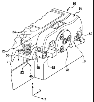
[0013] With reference to Figs. 1 and 2, the peristaltic pump assembly 10
generally includes a pump body 12 and a cassette 14 removably attached
thereto by an attachment member 15. In an illustrative example, the
peristaltic
pump assembly 10 will be described herein as including a mounting pin as the
attachment member 15 (though it is to be understood that various alternate
examples of the attachment member 15 may be used). Details of an examply of
a method of removably attaching the cassette 14 to the pump body 12 via the
mounting pin 15 may be found in U.S. Patent No. 7,934,912, which is commonly
owned by the Assignee of the present disclosure. It is to be understood,
however, that other suitable means and/or methods for removably attaching the
cassette 14 to the pump body 12 may also be considered as being within the
spirit and scope of the present disclosure.
[0014] The pump body 12 further includes a cassette receiving portion 16
having a partial cavity 20 defined by a floor (not shown) and two opposing
walls
22, 24. A roller assembly 26 (e.g., a roller mechanism) is housed within the
cavity 20 and operatively connected to the pump body 12. Roller assembly 26
includes a plurality of satellite rollers 28 arranged in a planetary
configuration.
The rollers 28 rotate as an assembly, as well as individually, in response to
rotational forces imparted thereto by a motorized drive shaft (not shown). The
CA 02708213 2012-06-04
4
motorized drive shaft may be operated by a pump motor (not shown), which are
both operatively connected to the pump body 12.
[0015] An exploded view of the cassette 14 is generally depicted in Fig.
3,
where the cassette 14 includes a cassette body 30 and a cover 32 disposed
thereon. The cassette 14 may be disposable, as desired. The cassette body 30
includes an inlet 34 formed in an end 36 thereof and an outlet 38 formed in
another end 40 thereof. The inlet 34 and outlet 38 are configured to receive
first
and second ends of a tube 42 (shown in Fig. 1), thereby supporting the tube 42
in the cassette 14.
[0016] In a non-limiting example, the tube 42, which is also disposable,
may be classified as substantially flexible so that the tube may be compressed
and/or occluded by the rollers 28, as will be described further below. In an
embodiment, the tube 42 is made of a polymeric material. Non-limiting examples
of suitable polymeric materials include silicones, AUTOPRENETm (an opaque
thermoplastic rubber with high wear resistance derived from SANTOPRENETm,
commercially available from Advanced Elastomer Systems, a subsidiary of
ExxonMobil Chemical located in Houston, TX), VITONTm (a black fluoroelastomer
with resistance to concentrated acids, solvents, ozone, radiation and
temperatures up to 200 C with good chemical compatibility, commercially
available from DuPont Performance Elastomers located in Wilmington,
Delaware), TYGON TM (good chemical resistance with a clear finish,
commercially
available from Saint-Gobain Performance Plastics Corporation located in Akron,
Ohio), PROTHANE IITm (a transparent, blue, polyester, polyurethane tubing with
good chemical resistance, commercially available from Randolph Austin
Company located in Manchaca, Texas), and/or the like, and/or combinations
thereof. The inner diameter of the tube 42 may be selected based on the
desirable flow rates and the desirable viscosities of the fluid that will flow
therethrough.
CA 02708213 2012-06-04
[0017] The cassette 14 further includes a race 44 formed therein and
configured to provide a compression surface for the tube 42. It is to be
understood that during operation of the pump, the rollers 28 apply a
compression force against the tube 42 in response to rotational movement of
the rollers 28. The compression force compresses the tube 42 against the race
44 to thereby substantially occlude the tube 42. This compression force is a
predetermined force controlled by a regulator 46 of the pump assembly 10. As
such, in response to the rotational movement of the rollers, portions of the
flexible tube 42 that are in contact with the rollers 28 compress or are
otherwise
occluded against a wall of the cassette 14. As a result, fluid is temporarily
retained in the tube 42 between the occluded points. In this manner, fluid is
urged through the tube 42 via peristaltic wave action. Details of an example
of
a suitable cassette 14 may be found in U.S. Patent No. 8,062,008, which is
commonly owned by the Assignee of the present disclosure.
[0018] As depicted in Fig. 4, the regulator 46 is disposed in the pump
body 12 and is operatively connected to the cassette 14. It is to be
understood,
however, that the regulator 46 may otherwise be disposed in the peristaltic
pump assembly 10, e.g. adjacent to the pump body 12 and/or as part of the
pumping mechanism assembly. In an embodiment, the regulator 46 includes a
slide member 48 having the mounting pin 15 connected thereto. The slide
member 48 may be any suitable support member capable of moving along a
substantially linear path of length L. In an embodiment, and as shown in Fig.
4,
a window 52 is formed in the pump body 12. At least a portion of the slide
member 48 extends through the window 52. The window 52 is configured to
allow the slide member 48 (including the mounting pin 15 connected thereto) to
linearly slide or otherwise move a distance along a length L in response to
changes/variations in the pump assembly 10 or components thereof (e.g.,
variations in the wall thickness of the tube 42 at the compression area of the
race 44, wear of the rollers 28, thermal length variations of components,
manufacturing variations, etc.).
CA 02708213 2012-06-04
5a
[0019] Movement of the slide member 48 (e.g., in the window 52) may be
restricted by the regulator 46 via a spring 50 also provided therewith and
operatively connected to the slide member 48. The spring 50 may be
operatively situated such that the spring 50 compresses along substantially
the
same linear direction as the slide member 48. In an embodiment, the spring 50
may be selected from those having a spring constant ranging from about 3
lbf/in
(0.525 N/mm) to about 5 lbdin (0.875 N/mm). Non-limiting examples of suitable
springs include helical springs, clock springs, torsion springs, compression
springs, extension springs, leaf springs, elastomeric bodies, and/or the like,
and/or combinations thereof.
CA 02708213 2010-06-07
WO 2009/042182
PCT/US2008/011131
6
[0020] In an embodiment, a predetermined pre-load may be applied to
the spring 50 using a pre-loading member 54 operatively connected thereto. As
shown in Fig. 4, the pre-loading member 54 may be a shoulder bolt extending
through the spring 50 and through a bore (not shown) formed in the slide
member 48. It is to be understood that other devices may suitably be used as
the pre-loading member 54, non-limiting examples of which include screws,
pegs, pins, shafts, and/or the like, and/or combinations thereof. In a non-
limiting
example, the predetermined pre-load applied to the spring 50 ranges from about
1.5 lbf (7 N) to about 3 lbf (14 N).
[0021] The regulator 46 is generally configured to regulate and/or
control
the compression force applied to the tube 42 by the rollers 28 so that the
compression force is a substantially constant force. To accomplish this, the
regulator 46 restricts the amount of the compression force applied to the tube
42
within a predetermined boundary or range. The predetermined boundary or
range may be determined, e.g., based on the spring constant of the spring 50
and the distance that the slide member 48 travels in order to compress the
spring 50. Restricting the amount of the compression force may be
accomplished by allowing the mounting pin 15 (which is connected to the slide
member 48) to move in response to changes and/or variations in the peristaltic
pump assembly 10. In a non-limiting example, such changes and/or variations
include variations in the individual components of, or the assembly 10 as a
whole (as mentioned above), e.g., when the assembly 10 is infusing a fluid to
a
patient.
[0022] In an embodiment, before the cassette 14 is mounted to the pump
body 12, the slide member 48 is slightly pre-loaded (e.g., a pre-load of about
2
lbf to about 2.5 lbf) via compression of the spring 50. Upon mounting the
cassette 14, the slide member 48 moves in the y-direction from its pre-load
position, and the spring 50 compresses slightly further beyond the pre-load
force. The tube 42 is substantially occluded under the force applied by the
spring 50. During operation of the roller mechanism, as the rollers 28 rotate,
slight variations and/or changes in the size of the tube 42, various
components
of the cassette 14, the rollers 28, and/or the like are controlled by the
slide
member 48 by moving the slide member 48, against the spring 50, in the y-
CA 02708213 2010-06-07
WO 2009/042182
PCT/US2008/011131
7
direction along the substantially linear path of length L. It is to be
understood
that movement of the slide member 48 is relatively small in order to
sufficiently
control the changes in the pump assembly 10 components, etc., and to maintain
a substantially constant compression force applied to the tube 42 by the
rollers
28. In a non-limiting example, the slide member 48 moves a length L ranging
from about 0.25 mm to about 0.5 mm.
[0023] Although the pump assembly 10 has been described including the
regulator 46 operatively connected to the mounting pin 15, it is to be
understood
that the regulator 46 may otherwise be operatively connected to a pump body
retaining feature 56 (shown in Fig. 2) disposed or otherwise formed in the
pump
body 12. In an embodiment, the pump body retaining feature 56 is configured
to matingly engage a cassette retaining feature 58 (shown in Fig. 3) formed on
the cassette body 30, thereby securing the cassette 14 to the pump body 12
when assembled therewith.
[0024] Also disclosed herein is a method of regulating the predetermined
force applied to the tube 42 by a plurality of rollers 28 in the peristaltic
pump
assembly 10, thereby compressing the tube 42. The method is accomplished
by providing pump assembly 10 including the regulator 46, and regulating the
predetermined force applied to the tube 42.
[0025] It is to be understood that the term "connect/connected" or the like
is broadly defined herein to encompass a variety of divergent connecting
arrangements and assembly techniques. These arrangements and techniques
include, but are not limited to (1) the direct connection between one
component
and another component with no intervening components therebetween; and (2)
the connection of one component and another component with one or more
components therebetween, provided that the one component being "connected
to" the other component is somehow operatively coupled to the other
component (notwithstanding the presence of one or more additional
components therebetween).
[0026] While several embodiments have been described in detail, it will
be apparent to those skilled in the art that the disclosed embodiments may be
modified. Therefore, the foregoing description is to be considered exemplary
rather than limiting.