Note: Descriptions are shown in the official language in which they were submitted.
CA 02720379 2010-10-01
1
DEVICE FOR DISPENSING EFFERVESCENT BEVERAGES AND A THREE-WAY
VALVE
The invention relates to the field of food industry, more particularly, to
commercial
equipment, and is useful in apparatuses for dispensing beer and other foaming
and/or carbonated
beverages from an isobaric storage to plastic bottles or glasses for sale in
retail kiosks, shops,
restaurants, and bars.
Flow-switch apparatuses are known for use in systems for dispensing various
kinds of
foaming beverages (see RU 13369 U1, US 6164083), these apparatuses comprising
a kit of taps,
each installed in a pipeline connected to beverage storage. Each storage
contains a beverage of a
certain kind.
However, such flow-switch apparatuses do not provide the counter-pressure
dispensing of
beverages from isobaric storages to covered or uncovered containers (plastic
bottles or mugs).
A multi-way cock is known for flow switching (see RU 2175735 Cl), the cock
comprising housing with an inlet mouth and several outlet mouths, a cover, a
swing stem, and a
seal made in the form of two ceramic disks contacting with each other. One of
the disks is
immovably fixed in the saddle of the housing and the other is mounted so as to
allow an
interaction with the swing stem. In the immovable disk, there are several
through windows; in
the movable disk, there is a pit for mouths to communicate with one another.
A drawback of this piece of the prior art consists of that flows can mix upon
switching.
The closest prior art for the three-way cock of the present invention is a
three-way flow
switch of an apparatus for a manual dispensing of foaming and/or carbonated
beverages, this
switch comprising a cylinder-shaped housing with a cover wherein two through
inlet holes and
one outlet hole are made in the bottom of the housing and wherein an upper
disk having an
option of rotating and an immovably fixed lower disk are coaxially mounted
inside the housing;
the upper disk is rigidly connected via a hole in the cover to a lever
positioned outside the
housing of the three-way flow-switch, through holes are made in the lower disk
coaxially to the
holes in the bottom of the housing, and a sickle-shaped non-through groove is
made in the body
of the upper disk on the side facing the lower disk and opposing the holes
therein for one inlet
hole of the housing to communicate with the outlet hole thereof, wherein an
elastic seal is made
CA 02720379 2010-10-01
2
around the lever underneath the cover of the housing to press the upper disk
and the lower disk
to each other and to the bottom of the housing and wherein elastic annular
seals are mounted in
the holes of the bottom of the housing (see RU 36371 U1).
A drawback of this three-way flow switch consists of a low reliability of
performance and
difficulty of the maintenance thereof because of the need for washing disks
and seals after the
dispensing of beer or another foaming or carbonated beverage is over.
The closest art for the apparatus for a manual dispensing of beverages of the
present
invention consists of the apparatus for a manual dispensing of foaming and/or
carbonated
beverages to mugs or glasses comprising a housing equipped with a stage for
positioning a mug
or glass and a filling pipe mounted vertically on the stage for connecting it
via a flow switch
(cock) to a pressurized beer supply pipeline, the end of the pipe being
positioned above the stage
with a mug or glass and bent downward and toward the mug or glass (see US
7278454). To the
filling pipe, attached is an additional tipped pipe, which is lowered into a
mug or glass and has a
unit for laminarizing the beverage flow to reduce foaming during the
dispensing of the beverage
to the container.
A drawback of this apparatus is the need for a sanitary treatment of the
tipped pipe each
time a container is filled, which reduces the convenience of use of the
apparatus and increases
the time to serve a customer. Further, the apparatus fails to provide the
counter-pressure
dispensing of a beverage from isobaric storages to mugs and glasses, thereby
considerably
slowing down the dispensing of a beverage to small containers.
The technical result of the present invention is a simplified maintenance both
of the
apparatus for a manual dispensing of beverages as a whole due to excluding the
need for a
sanitary treatment of a part of the filling pipe each time a container is
filled and a simplified
maintenance of taps due to eliminating the need for frequent washing of units
and parts of these
means after the dispensing of beer or another beverage is over.
The technical result is reached by that, in a three-way cock (in the first
embodiment)
containing a hollow cylinder-shaped housing equipped with two inlet ducts and
one outlet duct
and a means for switching on or switching off one of the inlet ducts with the
outlet duct mounted
inside the housing with a control lever, according to the present invention,
the hollow cylinder-
shaped housing has three consecutively arranged annular compartments, the
inlet ducts being
connected to the first and third compartments and the outlet duct being
connected to the second
(middle-positioned) compartment, the means for switching on and switching off
the inlet ducts
contains a valve with an elastic face seal having an axial duct with an
elastic annular seal,
CA 02720379 2010-10-01
3
arranged in the third compartment of the housing, and positioned in the saddle
of the valve with
an option of an axial reciprocating movement thereof, and a stem arranged
inside the housing of
the cock with an option of an axial reciprocating movement thereof, one end of
the stem going
out the housing through its end wall and kinematically connected to the
control lever and the
other end positioned in the opposite third compartment of the housing, passing
through the axial
duct of the valve with the annual elastic seal, and kinematically connected
thereto by means of a
first spring which presses the valve from the end of the stem to the saddle of
this valve, the
saddle being formed by the ledge in the wall of the housing between the second
compartment
and the third compartment thereof and the annular ledge made on the stem;
further, the stem has
an axial duct closed on both ends by plugs, a first series of radial through
holes made in the stem
for communicating the axial duct thereof with the first compartment of the
housing and a second
series of radial through holes made in the stem behind the annular ledge
thereof along the
arrangement of the compartments of the housing for communicating the axial
duct of the stem
with the second compartment of the housing, wherein elastic annular seals are
installed between
the housing and the stem on both sides of the first compartment of the
housing, and the second
compartment and the third compartment are hermetically isolated from each
other by means of
the aforementioned valve. The valve can optionally be pressed in the axial
direction to the saddle
of the valve by means of a second spring through the stem, this second spring
located around the
stem and kinematically connected thereto and to the housing.
The aforementioned technical result is also reached by that in the three-way
cock (a
second embodiment) containing a hollow cylinder-shaped housing with two inlet
or outlet ducts
and one outlet or inlet duct and a means installed in the housing with a
control lever for
switching on or switching off one of the inlet or outlet ducts with the outlet
or inlet duct,
according to the presence invention, the hollow cylinder-shaped housing of the
cock has three
consecutively arranged annular compartments, the inlet or outlet ducts being
connected to the
first and third compartments and the inlet or outlet duct being connected to
the second (middle-
positioned) compartment; the means for switching on and switching off the
outlet or inlet ducts
contains two valves with elastic face seals having axial ducts with elastic
annular seals, arranged
in the second compartment of the housing of the cock, and positioned in the
saddles of the valves
with an option of an axial reciprocating movement thereof, and a stem arranged
inside the
housing with an option of an axial reciprocating movement thereof, one end of
the stem going
out the housing through the end wall thereof and kinematically connected to
the control lever and
the other end positioned in the first compartment of the housing and sealed to
the wall thereof by
CA 02720379 2010-10-01
4
means of an annular elastic seal, passing through the axial ducts of the
valves with annual elastic
seals, and kinematically connected thereto by means of a spring which is
positioned around the
stem between the annular valves and presses the valves to the saddles of these
valves, the saddles
being formed by the ledges in the wall of the housing between the first,
second, and third
compartments thereof and the annular ledges made on the stem; further, the end
of the stem on
the side opposing the lever has an axial duct with an open end having a length
matching the size
of the first compartment of the housing and communicating with this
compartment via radial
through holes made in the stem in front of the closed end of the axial duct
thereof, wherein the
first and third compartments are hermetically isolated from the second
compartment by means of
the aforementioned valves which are pressed by a spring in the axial direction
to the saddles of
these valves.
In both embodiments of the three-way cock, the control lever is equipped with
a lock to
fix the position thereof relative to the housing of the cock.
The aforementioned technical result is also reached by that in an apparatus
for a manual
dispensing of foaming and/or carbonated beverages to uncovered containers
including a housing
with a stage for positioning an uncovered container thereon and a filling pipe
mounted thereon
for feeding a beverage, one end of the pipe being arranged above the place
where the uncovered
container is positioned, according to the present invention, the apparatus is
equipped with a cap
which is hermetically fastened to the stage, with an option of being
disconnected, under which
there are the filling pipe and the place where the uncovered container is
positioned; a unit for
fastening the cap and supplying or removing the container from under it; and a
unit for supplying
under pressure a beverage or gas to underneath the cap and removing the gas
therefrom. The unit
for supplying under pressure the beverage or gas to underneath the cap and
removing the gas
therefrom contains a flow switch, through which the inlet end of the filling
pipe is connected to a
beverage supply pipeline for supplying the beverage from the isobaric storage
and a gas supply
pipeline for supplying the gas from the gas cylinder, and a pipe having one
end thereof
connected to the internal space of the cap and the other connected with the
atmosphere through
the flow switch.
The flow switch is embodied in the form of two three-way cocks equipped with
control
levers according to claims 1 and 3, wherein the outlet duct of the first cock
(according to claim
1) is connected to the filling pipe, two inlet ducts are connected with,
respectively, the gas supply
pipeline for supplying the gas from the gas cylinder and the beverage supply
pipeline for
supplying the beverage from the isobaric capacity, and the second cock
(according to claim 3)
CA 02720379 2010-10-01
contains an inlet duct connected via a pipeline to the end of the pipe for
removing the gas from
under the cap and two outlet ducts for gas release, one being connected to the
second cock via a
throttle for controlling the leaving gas flow rate from the removable cap.
The unit for fastening the cap and for supplying or removing a container from
under the
5 cap contains an annular elastic seal, positioned on the stage of the housing
and having the size
matching the size of the end of the removable cap, and bayonet connections
arranged on the
stage and the removable cap around the end of the cap and around the annular
elastic seal.
The invention is illustrated by the following drawings:
FIG. 1 represents a scheme of the three-way cock in the initial position (the
first
embodiment);
FIG. 2 represents a scheme of the three-way cock in the initial position (the
first
embodiment);
FIG. 3 represents a scheme of the apparatus for a manual dispensing of foaming
and/or
carbonated beverages to uncovered containers (in the initial position)
containing the claimed
embodiments of the three-way cock;
FIG. 4 represents a scheme of the apparatus for a manual dispensing of foaming
and/or
carbonated beverages to uncovered containers (in the position where gas supply
ducts are open)
containing the claimed embodiments of the three-way cock;
FIG. 5 represents the same in the position where beverage supply ducts are
open;
FIG. 6 represents the same in the position where gas release ducts are open.
In the first embodiment, the three-way cock contains a hollow cylinder-shaped
housing 1
equipped with two inlet ducts 2 and 3 and one outlet duct 4 and a means
installed inside the
housing 1 with a control lever 5 for switching on or switching off one of the
inlet ducts 2 and 3
with the outlet duct 4. The hollow cylinder-shaped housing 1 has three
consecutively arranged
annular compartments 6, 7, and 8, the inlet ducts 2 and 3 being connected to
the first
compartment 6 and the third compartment 7, respectively, and the outlet duct 4
being.connected
to the second (middle-positioned) compartment 7. The means for switching on
and switching off
the inlet ducts contains a valve 9 with an elastic face seal 10, this valve
having an axial duct with
an elastic annular seal 11, arranged in the third compartment 8 of the housing
I and positioned in
the saddle of the valve 9 with an option of an axial reciprocating movement
thereof. A stem 12 is
arranged inside the housing of the cock with an option of an axial
reciprocating movement
thereof, one end 13 of the stem going out the housing I through the end wall
thereof and
kinematically connected to the control lever 5 and the other end 14 of the
stem positioned in the
CA 02720379 2010-10-01
6
opposite third compartment 8 of the housing 1, the stem passing through the
axial duct of the
valve 9 with the annual elastic seal 10 and kinematically connected thereto by
means of a first
spring 15 which presses the valve 9 from the end 14 of the stem 12 to the
saddle of the valve 9.
The saddle of the valve 9 is formed by the ledge 16 made in the wall of the
housing 1 between
S the second compartment 7 and the third compartment 8 thereof and the annular
ledge 17 made on
the stem 12. The stem 12 has an axial duct 18 closed on both ends thereof by
plugs 19 and 20, a
first series of radial through holes 21 made in the stem 12 for communicating
the axial duct 18
thereof with the first compartment 6 of the housing and a second series of
radial through holes 22
made in the stem 12 behind the annular ledge 17 thereof along the arrangement
of the
compartments 6 - 8 of the housing for connecting the axial duct 18 of the stem
with the second
compartment 7 of the housing. Elastic annular seals 23 and 24 are installed
between the housing
1 and the stem 12 on both sides of the first compartment 6 of the housing, and
the second
compartment 7 and the third compartment 8 are hermetically isolated from each
other by means
of the valve 9. Further, the valve 9 is pressed in the axial direction to the
saddle of this valve by
means of a second spring 25 through the stem 12, this second spring located
around the stem and
kinematically connected thereto and to the housing 1.
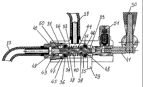
In the second embodiment, the three-way cock contains a hollow housing 26 with
two
inlet or outlet ducts 27 and 28 and one outlet or inlet duct 29 and a means
installed inside the
housing with a control lever 30 for switching on or switching off one of the
inlet or outlet ducts
27 and 28 with the outlet or inlet duct 29. The hollow cylinder-shaped housing
26 of the cock has
three consecutively arranged annular compartments 31, 32, and 33, the inlet or
outlet ducts 27
and 28 being connected to the first compartment 31 and the third compartment
33 and the inlet or
outlet duct 29 being connected to the second (middle-positioned) compartment
32. The means
for switching on and switching off the outlet or inlet ducts 26 and 27
contains two valves 34 and
35 with elastic face seals 36 and 37 having axial ducts with elastic annular
seals 38 and 39,
arranged in the second compartment 32 of the housing of the cock and
positioned in the saddles
of the valves 34 and 35 with an option of an axial reciprocating movement
thereof. A stem 40 is
arranged inside the housing 26 with an option of an axial reciprocating
movement thereof, one
end 41 of the stem going out the housing through the end wall thereof and
kinematically
connected to the control lever 30 and the other end 42 thereof positioned in
the first compartment
31 of the housing and sealed to the wall thereof by means of an annular
elastic seal 43, the stem
passing through the axial ducts of the valves 34 and 35 with annual elastic
seals and
kinematically connected thereto by means of a spring 44 which is located
around the stem 40
CA 02720379 2010-10-01
7
between the annular valves 34 and 35 and presses the valves to the saddles of
the valves 34 and
35. The saddles of the valves 34 and 35 are formed by ledges 45 and 46 made in
the wall of the
housing 26 between the first, second, and third compartments 31 - 33 thereof
and annular ledges
47 and 48 made on the stem 40. The end 42 of the stem on the side opposing the
lever has an
axial duct 49 with an open end having a length matching the size of the first
compartment 31 of
the housing and communicating with this compartment via radial through holes
50 made in the
stem 40 in front of the plugged end of the axial duct 49 of the stem. The
first compartment 31
and the third compartment 33 are hermetically isolated from the second
compartment 32 by
means of the aforementioned valves 34 and 35 which are pressed by the spring
44 in the axial
direction to the saddles of these valves.
In both embodiments of the three-way cock, the control lever (5 or 30) of the
cock is
equipped with a lock 51 to fix the position thereof relative to the housing (1
or 26) of the cock.
Both embodiments of the aforementioned cocks are used in an apparatus for a
manual
dispensing of foaming and/or carbonated beverages to uncovered containers.
The apparatus includes a housing 52 with a stage 53 for positioning an
uncovered
container 54 thereon and a filling pipe 55 mounted thereon for feeding a
beverage. One end of
the pipe 55 is arranged above the place where the uncovered container 54 is
positioned. The
apparatus is equipped with a cap 56 which is hermetically fastened to the
stage, with an option of
being disconnected, under which there are the filling pipe 55 and the place
where the uncovered
container 54 is positioned; a unit for fastening the cap and supplying or
removing the container
54 from under it; and a unit for supplying under pressure a beverage or gas to
underneath the cap
56 and removing the gas therefrom.
The means (Fig. 3) for fastening the cap and supplying or removing the
container 54 from
under the cap 56 contains an annular elastic seal 57 positioned on the stage
53 of the housing,
having the size matching the size of the end of the removable cap 56, and
bayonet connections
58 positioned on the stage 53 and the removable cap 56 around the end of the
latter and around
the annular elastic seal 57.
The unit for supplying under pressure a beverage or gas to underneath the cap
56 and for
removing the gas therefrom contains a flow switch 59, through which the inlet
end of the filling
pipe 55 is connected to a beverage supply pipeline 60 for supplying the
beverage from the
isobaric storage and to a gas supply pipeline 61 for supplying the gas from
the gas cylinder; and
a pipe 62 having one end thereof connected to the internal space of the cap
and the other
connected with the atmosphere through the flow switch 59.
CA 02720379 2010-10-01
8
The flow switch is embodied in the form of two three-way cocks 63 and 64 with
control
levers 5 and 30. The outlet duct 4 of the cock 63 is connected to the filling
pipe 55; the two inlet
ducts 2 and 3 thereof are, respectively, connected to the beverage supply
pipeline 60 for
supplying the beverage from isobaric storage and to the gas supply pipeline 61
for supplying the
gas from the gas cylinder. The second cock 64 contains an inlet duct 28, which
is connected to
the end of the pipe 62 for removing the gas from under the cap 56, and two
outlet ducts 29 and
27 for gas release. The duct 29 of the cock 64 is connected to the inlet duct
65 of a throttle 66 for
controlling the removed gas flow rate from the removable cap 56, and the
outlet duct 67 is
connected to the outlet duct 27 of the cock 64 by means of the pipe 68.
The three-way cocks in the apparatus for a manual dispensing of foaming and/or
carbonated beverages to uncovered containers and the apparatus itself operate
in the following
manner.
According to the scheme (FIG. 3), the apparatus is used for a manual filling
of an
uncovered container (a glass or a mug) with a foaming and/or carbonated
beverage from an
isobaric storage under counter-pressure. For this purpose, for example, the
glass 54 is placed on
the stage 53 under the end of the filling pipe 55 and is covered with a
removable cap 56, which is
hermetically connected to the stage 53 by means of the annular elastic seal 57
and bayonet
connections 58. While so doing, the throttle 66 is closed. The levers 5 and 30
of the three-way
cocks 63 and 64 (FIG. 3) are in a neutral vertical position, indicating that
these cocks are in the
closed position. Then, the lever 5 (FIG. 4) of the three-way cock 63 is
declined by 20 degrees
outward the operator to move the stem 12 by compressing the spring 15 and
expanding the
additional spring 25 (FIG. 4). The valve 9 remains pressed to the saddle, and
the radial holes 22
open and provide the communication of the chamber 6 with the chamber 7. The
duct 2, which is
connected via the pipeline 61 to the gas cylinder, communicates via the
chamber 6, radial holes
21, axial duct 18, radial holes 22, chamber 7, outlet duct 4, and filling pipe
55 with the internal
space of the removable cap 56. Gaseous CO2 from the cylinder is supplied to
underneath the cap
56, where the pressure is equalized to the pressure in the gas cylinder. Then,
the lever 5 of the
three-way cock 63 (FIG. 5) is deflected by 40 degrees in the opposite
direction. Upon this, the
stem 12, together with the valve 9, moves to open the latter, by expanding the
spring 15 and
compressing the additional spring 25. Once the valve 9 is open, the chambers 7
and 8 are in
communication with each other. The duct 3, which is connected by means of the
pipeline 60 to
the isobaric beverage storage, communicates via chambers 8 and 7, duct 4, and
filling pipe 55
with the internal space of the removable cap 56. Inasmuch as the pressure
under the cap 56 and
CA 02720379 2010-10-01
9
in the isobaric storage is the same, the beverage is not supplied to
underneath the said cap 56.
Then, the lever 30 (FIG. 5) of the three-way cock 64 is deflected by 20
degrees toward the
operator to move the stem 40 by compressing the spring 44 (FIG. 5). The valve
34 remains
pressed to the saddle (that is, it is closed), and the valve 35 opens to
connect the inlet duct 28
through the chambers 32 and 33 to the throttle 66. Then, while the cocks 63
and 64 are in the
position shown in FIG. 5, the throttle 66 is open and gaseous CO2 through the
pipe 62, the inlet
duct 28, the chambers 32 and 33, and the ducts 65 and 67 of the throttle 66 is
forced out from
under the cap 56 to the atmosphere. A pressure difference is created between
the inside of the
isobaric storage and underneath the cap 56, causing the beverage to fill the
glass 54. Elimination
of foaming is provided by creating a gas pressure in the dispensing system and
above the
beverage surface in the glass 54, this pressure exceeding the saturation
pressure of the gas
dissolved in the beverage. Once the glass 54 is filled with the beverage, in
order to stop the
further supply of the beverage from the isobaric storage, the lever 5 of the
cock 63 is deflected
(by 20 degrees) to the neutral initial vertical position (as in FIG. 6)
together with the stem 12 and
the valve 9, thereby closing the three-way cock 63. The residual gas from
under the cap 56 and
in part the dissolved gas released from the beverage are removed by deflecting
the lever 30 of the
cock 64 by 40 degrees to the other extreme position (FIG. 6) of the
displacement of the stem 40
by compressing the spring 44. The valve 35 returns to the initial closed
position thereof, and the
valve 34 opens to communicate the inlet duct 28 to the atmosphere via the
chambers 32 and 31,
radial holes 50, axial duct 49, and pipe 27. After the pressure under the
removable cap 56 is
equalized to the atmospheric pressure, the levers 5 and 30 of both cocks 63
and 64 are put in the
initial vertical position where these cocks are in the closed position (FIG.
3), the cap 56 is turned
to disconnect the bayonet connections 58, the cap 56 is removed, and the glass
54 filled with the
beverage is given to the customer.
The three-way cocks and the apparatus for a manual dispensing of foaming
and/or
carbonated beverages to uncovered containers of the present invention provide
a simplified
maintenance of the apparatus as a whole due to excluding the need for a
sanitary treatment of a
part of the filling pipe after each filling of a container, and a simplified
maintenance of taps due
to excluding the need for frequent washing of units and parts of these means
after the dispensing
of beer or another beverage is over.