Note: Descriptions are shown in the official language in which they were submitted.
CA 02723083 2010-10-29
WO 2010/031029 PCT/US2009/056914
ENERGY MANAGEMENT OF CLOTHES DRYER
APPLIANCE
BACKGROUND
[0001] This disclosure relates to energy management, and more particularly to
energy
management of household consumer appliances. The disclosure finds particular
application to
changing existing appliances via add-on features or modules, and incorporating
new energy
saving features and functions into new appliances.
[0002] Currently utilities charge a flat rate, but with increasing cost of
fuel prices and
high energy usage at certain parts of the day, utilities have to buy more
energy to supply
customers during peak demand. Consequently, utilities are charging higher
rates during peak
demand. If peak demand can be lowered, then a potential huge cost savings can
be achieved and
the peak load that the utility has to accommodate is lessened.
[0003] One proposed third party solution is to provide a system where a
controller
"switches" the actual energy supply to the appliance or control unit on and
off. However, there is
no active control beyond the mere on/off switching. It is believed that others
in the industry
cease some operations in a refrigerator during on-peak time.
[0004] For example, in a refrigerator most energy is consumed to keep average
freezer
compartment temperature at a constant level. Recommended temperature level is
based on
bacteria multiplication. Normally recommended freezer temperature for long (1-
2 month) food
storage is 0 degrees F. Research shows that bacteria rise is a linear function
of the compartment
temperature, i.e., the lower the temperature the lower the bacteria
multiplication. Refrigerator
designers now use this knowledge to prechill a freezer compartment (and in
less degree a
refrigerator compartment also) before defrost, thus keeping an average
temperature during time
interval that includes before, during, and after defrost at approximately the
same level (for
example, 0 degrees F).
[0005] There are also currently different methods used to determine when
variable
electricity-pricing schemes go into effect. There are phone lines, schedules,
and wireless signals
sent by the electrical company. One difficulty is that no peak shaving method
for an appliance
1
CA 02723083 2010-10-29
WO 2010/031029 PCT/US2009/056914
2
such as a refrigerator will provide a maximal benefit. Further, different
electrical companies use
different methods of communicating periods of high electrical demand to their
consumers. Other
electrical companies simply have rate schedules for different times of day.
[0006] Electrical utilities moving to an Advanced Metering Infrastructure
(AMI) system
will need to communicate to appliances, HVAC, water heaters, etc. in a home or
office building.
All electrical utility companies (more than 3,000 in the US) will not be using
the same
communication method to signal in the AMI system. Similarly, known systems do
not
communicate directly with the appliance using a variety of communication
methods and
protocols, nor is a modular and standard method created for communication
devices to interface
and to communicate operational modes to the main controller of the appliance.
Although
conventional WiFi/ZigBee/PLC communication solutions are becoming commonplace,
this
disclosure introduces numerous additional lower cost, reliable solutions to
trigger "load
shedding" responses in appliances or other users of power. This system may
also utilize the
commonplace solutions as parts of the communication protocols.
BRIEF DESCRIPTION
[0007] The present disclosure reduces power consumption during on-peak hours
by
reducing the energy demand on the power generation facility, and also enabling
the
user/consumer to pay less to operate the appliance on an annual basis. A
controller is configured
to receive and process a signal indicative of current state of an associated
energy supplying
utility. The controller operates the cooking appliance in one of a plurality
of operating modes,
including at least a normal operating mode and an energy savings mode, in
response to the
received signal.
[0008] This disclosure is a low-cost alternative to using expensive or
complicated
methods of determining when peak electrical rates apply. For example, when the
refrigerator is
in peak shaving mode (or it could be programmed to do this constantly), an
ambient light sensor
determines when it is morning, and then stays in energy-saving mode for a
predetermined
number of hours. Preferably, the system will need a counter to know that the
room has been
dark for a predetermined number of hours. When the lights come on for a
certain length of time,
CA 02723083 2010-10-29
WO 2010/031029 PCT/US2009/056914
3
then the system knows, for example, that it is morning. A state for an
associated energy
supplying utility is determined. The utility state is indicative of at least a
peak demand period or
an off-peak demand period.
[0009] This disclosure provides a peak-shaving appliance such as a
refrigerator,
including a method to determine when to go into peak-shaving mode without
using additional
components, or components that have another purpose, and provides a high
percentage of the
maximum benefit for negligible cost. The two components needed for this are an
ambient light
sensor and a timer. The kitchen will be dark for an extended period of time
while everyone is
sleeping. The light sensor and the timer will be used to determine that it is
nighttime and
morning can be determined by the light sensor. When the refrigerator
determines it is morning,
the timer will be used to initiate peak shaving mode after some delay time.
For example, peak
shaving mode could start three hours after it is determined morning starts.
Similarly, the ambient
light sensor can also be used for dimming the refrigerator lights. This
disclosure advantageously
uses ambient light to determine when to start peak shaving. A controller is
configured to receive
and process an energy signal. The signal has a first state indicative of a
utility peak demand
period and a second state indicative of a utility off-peak demand period. The
controller operates
the cooking appliance in one of an energy savings mode and a normal operating
mode based on
the received signal being in the first and second states respectively.
[0010] An appliance interface can be provided for all appliances leaving the
module to
communicate with the AMI system. The system provides for appliance sales with
a Demand Side
Management capable appliance. The Demand Side Management Module (DSMM) is
provided
to control the energy consumption and control functions of an appliance using
a communication
method (including but not limited to PLC, FM, AM SSB, WiFi, ZigBee, Radio
Broadcast Data
System, 802.11, 802.15.4, etc.). The modular approach will enable an appliance
to match
electrical utility communication requirements. Each electrical utility region
may have different
communication methods, protocol methods, etc. This modular approach allows an
appliance to
be adapted to a particular geographical area of a consumer or a particular
electrical provider.
The module can be added as a follow on feature and applied after the appliance
is installed.
Typical installations could include an integral mounted module (inside the
appliance or unit) or
CA 02723083 2010-10-29
WO 2010/031029 PCT/US2009/056914
4
an externally mounted module (at the wall electrical receptacle or anywhere
outside the
appliance or unit). The module in this disclosure provides for 2 way
communications if needed,
and will provide for several states of operation - for example, 1) normal
operation, 2) operation
in low energy mode (but not off), and 3) operation in lowest energy mode.
[0011] This module could be powered from the appliance or via a separate power
supply,
or with rechargeable batteries. The rechargeable batteries could be set to
charge under off-peak
conditions. With the module powered from the appliance, the appliance could
turn it off until the
appliance needed to make a decision about power usage, eliminating the standby
power draw of
the module. If powered separately, the appliance could go to a low energy
state or completely
off, while the module continued to monitor rates.
[0012] Use of RFID tags in one proposed system should offer significant
savings since
the RFID tags have become very low cost due to the proliferation of these
devices in retail and
will effectively allow the enabled appliance to effectively communicate with
the utility meter
(e.g., receive signals from the utility meter). This system makes it very easy
for a customer to
manage energy usage during peak demand periods and lowers the inconvenience
level to the
customer by not shutting off appliances in the home by the utility. When local
storage and local
generation are integrated into the system, then cost savings are seen by the
customer. This
system also solves the issue of rolling brownouts/blackouts caused by
excessive power demand
by lowering the overall demand. Also, the system allows the customer to pre-
program choices
into the system that will ultimately lower utility demand as well as save the
customer money in
the customer's utility billing. For instance, the customer may choose to
disable the defrost cycle
of a refrigerator during peak rate timeframes. This disclosure provides for
the controller to
"communicate" with the internal appliance control board and command the
appliance to execute
specific actions with no curtailment in the energy supply. This disclosure
further provides a
method of communicating data between a master device and one or more slave
devices using
RFID technology. This can be a number of states or signals, either using one
or more passive
RFID tags that resonate at different frequencies resonated by the master, or
one or more active
RFID tags that can store data that can be manipulated by the master device and
read by the slave
device(s). The states in either the passive or active RFID tags can then be
read by the
CA 02723083 2010-10-29
WO 2010/031029 PCT/US2009/056914
microcontroller on the slave device(s) and appropriate functions /actions can
be taken based
upon these signals.
[0013] Another exemplary embodiment uses continuous coded tones riding on
carrier
frequencies to transmit intelligence, for example, when one is merely passing
rate information
such as rate 1, 2, 3, or 4, using the tones to transmit the signals. One could
further enhance the
details of the messaging by assigning a binary number to a given tone, thus
allowing one to
"spell out" a message using binary coding with multiple tones. The appliance
microcomputer
would be programmed to respond to a given number that would arrive in binary
format.
[0014] One advantage of this approach is that customers have complete control
of their
power. There have been proposals by utilities to shut off customers if they
exceed demand limits
or increase the number of rolling brownouts. This method also gives a customer
finer granulity
in their home in terms of control. A customer does not have to load shed a
room just to manage
a single device.
[0015] This disclosure also advantageously provides modes of load shedding in
the
appliance, lighting, or HVAC other than "on/off' to make the situation more
acceptable from the
perspective of the customer.
[0016] In one aspect of the disclosure, a clothes dryer is provided comprising
one or
more power consuming functions and a controller in signal communication with
an associated
utility. The controller can receive and process a signal from the associated
utility indicative of
current cost of supplied energy. The controller operates the clothes dryer in
one of a normal
operating mode and an energy savings mode based on the received signal. The
controller is
configured to change the power consuming functions by adjusting one or more of
an operation
schedule, an operation delay, an operation adjustment, and a selective
deactivation of at least
one of the one or more power consuming functions to reduce power consumption
of the clothes
dryer in the energy savings mode.
[0017] In another aspect of the disclosure, a method for controlling a clothes
dryer is
provided, comprising: determining a cost of supplied energy from an associated
utility, the cost
CA 02723083 2010-10-29
WO 2010/031029 PCT/US2009/056914
6
being indicative of a peak demand period or an off-peak demand period;
operating the clothes
dryer in a normal mode during the off-peak demand period; operating the
clothes dryer in an
energy savings mode during the peak demand period; scheduling, delaying,
adjusting and/or
selectively deactivating any number of one or more power consuming
features/functions of the
clothes dryer to reduce power consumption of the clothes dryer in the energy
savings mode;
and, returning to the normal mode after the peak demand period is over.
[0018] An advantage of the present disclosure is the ability to produce
appliances with a
common interface and let the module deal with the Demand Side Management.
[0019] Another advantage is the ability to control functions and features
within the
appliance and/or unit at various energy levels, i.e., as opposed to just an
on/off function.
[0020] Another advantage is that the consumer can choose the module or choose
not to
have the module. If the module is chosen, it can be matched to the particular
electrical utility
service provider communication method of the consumer.
[0021] Another benefit is the increased flexibility with an associated
electrical service
provider, and the provision of several modes of operation (not simply an
on/off mode). The
module can be placed or positioned inside or outside the appliance and/or unit
to provide demand
side management.
[0022] Still other benefits relate to modularity, the ability to handle
multiple
communication methods and protocols without adversely impacting the cost of
the appliance,
opening up appliances to a variety of protocols, enabling demand side
management or energy
management, and/or providing for a standard interface to the appliance (for
example, offering
prechill and/or temperature set change during on-peak hours).
[0023] Low cost, reliable RF transmissions within the home, rather than using
industrial
solutions such as PLC or Zigbee solutions which are significantly more costly
than the
aforementioned system.
CA 02723083 2010-10-29
WO 2010/031029 PCT/US2009/056914
7
[0024] Still other features and benefits of the present disclosure will become
apparent
from reading and understanding the following detailed description.
BRIEF DESCRIPTION OF THE DRAWINGS
[0025] FIGURES 1-8, 9A, 9B and 10-21 illustrate exemplary embodiments of an
energy
management system for household appliances.
[0026] FIGURE 22 is a schematic illustration of an exemplary demand managed
clothes
dryer.
[0027] FIGURE 23 is an exemplary operational flow chart for the clothes dryer
of
FIGURE 22.
[0028] FIGURE 24 is an exemplary control response for the clothes dryer of
FIGURE
22.
DETAILED DESCRIPTION
[0029] In one embodiment, a more advanced system is provided to handle energy
management between the utility and the homeowner's appliances. The system can
include one or
more of the following: a controller, utility meter, communication network,
intelligent appliances,
local storage, local generator and/or demand server. Less advanced systems may
actually allow
the appliance to "communicate directly with the utility meter or mesh network
through the
DSSM (Demand Side Management Module) (Figure 1). The demand server is a
computer
system that notifies the controller when the utility is in peak demand and
what is the utility's
current demand limit. A utility meter can also provide the controller the
occurrence of peak
demand and demand limit. The demand limit can also be set by the home owner.
Additionally,
the homeowner can choose to force various modes in the appliance control based
on the rate the
utility is charging at different times of the day. The controller will look at
the energy
REPLACEMENT SHEET
SUBSTITUTE SHEET (RULE 26)
CA 02723083 2010-10-29
WO 2010/031029 PCT/US2009/056914
8
consumption currently used by the home via the utility meter and see if the
home is exceeding
the demand limit read from the server. If the demand limit is exceeded, the
controller will notify
the intelligent appliances, lighting and thermostat/HVAC (Figure 2).
[0030] Each intelligent appliance has a communication interface that links
itself to the
controller (Figure 3). This interface can be power-line carrier, wireless,
and/or wired. The
controller will interact with the appliance and lighting controls as well as
thermostat (for HVAC)
to execute the users preferences/settings.
[0031] Enabled appliances receive signals from the utility meter and help
lower the peak
load on the utility and lower the amount of energy that the consumer uses
during high energy
cost periods of the day. There are several ways to accomplish this, through
wireless
communication (ZigBee, WiFi, etc) or through PLC (power line carrier)
communication.
Alternatively, using passive RFID tags that resonate at different frequencies
resonated by the
master, or one or more active RFID tags that can store data that can be
manipulated by the
master device and read by the slave devices(s) is an effective and potentially
lower cost
communication solution since there is no protocol. Rather, a pulse of energy
at a particular
frequency will allow a low cost method with an open protocol for
transmitting/communicating
between a master device and one or more slave devices, and appropriate
functions/actions can be
taken based upon these signals.
[0032] The interaction between controller and appliances can occur in two
ways. For
example, in one scenario during a peak demand period, the controller will
receive a demand limit
from the utility, demand server or user. The controller will then allocate the
home's demand
based on two factors: priority of the appliance and energy need level (Figure
4). The priority
dictates which appliances have higher priority to be in full or partial energy
mode than other
appliances. Energy need dictates how much energy is required for a certain
time period in order
for that appliance to function properly. If the appliance's energy need is too
low to function
properly, the appliance moves to a normal mode or a higher energy need level.
The energy
saving mode is typically a lower energy usage mode for the appliance such as
shutdowns of
compressors and motors, delayed cycles, higher operating temperatures in
summer or lower
CA 02723083 2010-10-29
WO 2010/031029 PCT/US2009/056914
9
operating temperatures in winter until the peak demand period is over. Once
the demand limit is
reached, the appliances will stay in their energy mode until peak demand is
over, or a user
overrides, or appliance finishes need cycle or priority changes. The
controller constantly receives
status updates from the appliances in order to determine which state they are
in and in order to
determine if priorities need to change to accomplish the system goals.
[0033] In a second scenario, for example, a set point is provided. During a
peak demand
period, the controller will tell each appliance to go into peak demand mode
(Figure 5). The
appliance will then go into a lower energy mode. The customer can deactivate
the energy
savings mode by selecting a feature on the appliance front end controls (i.e.
user interface board)
before or during the appliance use or at the controller. The controller can
also communicate to a
local storage or power generation unit. This local unit is connected to the
incoming power
supply from the utility. The controller notifies the storage unit to charge
when it is not in peak
demand, if a storage unit is included and available. If the storage unit has
enough energy to
supply the appliances during peak demand, then the controller will switch the
home's energy
consumption from the utility to the storage unit. The unit can also be local
generator/storage such
as solar, hydrogen fuel cell, etc.
[0034] The central controller handles energy management between the utility
and home
appliances, lighting, thermostat/HVAC, etc. with customer choices incorporated
in the decision
making process. The controller may include notification of an energy saving
mode based on
demand limit read from one or more of a utility meter, utility, demand server
or user. An energy
savings mode of an appliance can thereby be controlled or regulated based on
priority and energy
need level sent from the controller and/or the customer (Figure 6). Likewise,
consideration to use
of local energy storage and use of a local generator to offset peak demand
limit can be
incorporated into the energy management considerations, or provide the ability
to override mode
of energy savings through the controller or at the appliance, lighting, or
thermostat/HVAC
(Figures 7 and 8).
[0035] The present disclosure has the ability for the home to shed loads in
pending
brown-out or black-out situations, yet have intelligence to prevent an
improper action such as
CA 02723083 2010-10-29
WO 2010/031029 PCT/US2009/056914
shutting down the refrigerator for extended timeframes that might compromise
food storage
safety.
[0036] How much energy the appliance consumes in peak demand is based on
priority of
the device and the energy need level. If the appliance's priority is high,
then the appliance will
most likely not go into a saving mode. The energy need level is based on how
little energy the
appliance can consume during peak demand and still provide the function
setting it is in (i.e. in a
refrigerator, ensuring that the temperature is cool enough to prevent
spoiling). It will also be
appreciated that an appliance may have multiple energy need levels.
[0037] The controller will be the main product with the communication and
settings
control incorporated within future appliances. Specific meters will be
selected so that the
controller can read the demand usage. It is intended that the demand server
will possibly be
purchased or leased to the utility.
[0038] A method is provided for constructing an appliance designed to perform
any key
function, the appliance comprises of several mechanical and electrical
elements controlled by a
main controller. This main controller has a port for receiving information
regarding the
operational state of the appliance. The port also has a user interface or
switch which could be
used to override the information received by the controller through the port.
Two-way or one-
way communication devices may be connected to the port. These communication
devices will
receive signals from a remote controller, process those signals and as a
result communicate an
operational state to the main controller of the appliance. This operational
state is communicated
to the main controller by one or more remote controllers in a specific format
determined by the
appliance. These signals from the remote controller(s) could be based on a
variety of
communication methods and associated protocols. On receiving the operational
state signal, the
appliance main controller causes the appliance to run a predetermined
operational mode. These
operational modes are designed into the appliance(s) and result in different
resource consumption
levels or patterns, even delaying use. Resources could include energy, water,
air, heat, sunlight,
time, etc. In future appliance models, the consumer might be given the
authority to modify the
appliance responses to a given rate signal. The consumer would be presented a
"check box" of
CA 02723083 2010-10-29
WO 2010/031029 PCT/US2009/056914
11
potential response modes and allowed to choose within set parameters. For
instance, the
consumer might be allowed to choose the amount of temperature adjustment a
refrigerator will
make in response to a high utility rate.
[0039] A method of communicating data between a master device and one or more
slave
devices may advantageously use continuous tone-coded transmission system. This
can be a
number of states or signals, either using one or more continuous tones that
signify different rate
states coming from the home area network (from meter) or the utility.
Additionally, one could
send a combination of tones to transmit binary messages using a few tones. The
slave devices
will incorporate a receiver that receives the carrier frequency and then
decodes the continuous
tone which corresponds to the particular state of the utility rate. Once the
"receiver board"
detects the tone, then the downstream circuitry will trigger the appropriate
response in the
appliance. The carrier frequency in this scheme can be numerous spectrums, one
being the FM
broadcast band or a specific FM band allocated by the FCC for low level power
output. The
advantage of broadcast band FM is the low cost of such devices and the
potential to penetrate
walls, etc. within a home with very low levels of power due to the long
wavelength of the 89-
106Mhz carrier. This process is used today in 2-way radio communications to
reduce the
annoyance of listening to multiple users on shared 2-way radio frequencies.
The process in these
radios is referred to as CTCSS (continuous tone-coded squelch system) and
would find
application in this end use.
[0040] Generally, it is not known to have modular interfaces that can receive
signals
from a control source. Also, no prior arrangements have functioned by
addressing the control
board of the appliance with a signal that directs the appliance to respond.
[0041] Thus, by way of example only, the structure and/or operation of a
refrigerator
(Figure 9, although other appliances are also represented) may be modified or
altered by
reducing the temperature, especially in the freezer compartment pre on-peak
time and further
temporarily provide a compartment temperature increase to shave on-peak load.
Specifically,
defrost operation could be delayed until off-peak time. Alternatively or
conjunctively, the freezer
and refrigerator temperature setpoints may be set to maintain less compressor
on time during on-
CA 02723083 2010-10-29
WO 2010/031029 PCT/US2009/056914
12
peak demand times. Similarly, the refrigerator/freezer could be programmed so
that lights will
not be permitted to come on or the lights must be dimmed lights during on-peak
demand times.
During on-peak demand times, the fan operating speeds can be reduced, and/or
compressor
operating speed reduced in order to reduce energy consumption. Still another
option is to reduce
the delay time for the door alarm to sound during on-peak time. Other power
load reducing
measures in a refrigerator may include (reducing before on-peak hours) the
temperature of the
freezer and refrigerator compartments in a refrigerator (prechill) and
slightly increase
temperature setting during on-peak rates. For example, just before peak rate
time, the
temperature setting could be decreased by 1-2 degrees (during off-peak rates).
Some
communication line with the electrical company could be established. Thus, the
electrical
company may be able to send a signal in advance to prechill the refrigerator
(or in the case of an
air conditioner, decrease the room temperature during off-peak rates as a pre-
chill maneuver)
and, in turn, increase the temperature setting during on-peak rates.
[0042] Still other energy consuming practices of the exemplary refrigerator
that may be
altered include turning the ice-maker off during on-peak demand times, or
disabling the crushed
ice mode during on-peak demand times. Alternatively, the consumer may be given
the ability to
select via a user interface which items are incorporated into the on-peak
demand via an
enable/disable menu, or to provide input selection such as entry of a zip code
(Figure 10) in order
to select the utility company and time of use schedule (Figure 11), or using a
time versus day of
the week schedule input method (Figures 12-13).
[0043] The user interface may also incorporate suggested energy saving tips or
show
energy usage, or provide an indicator during on-peak mode, or provide a
counter to illustrate the
energy impact of door opening, or showing an energy calculator to the consumer
to serve as a
reminder of the impact of certain selections/actions on energy use or energy
conservation
(Figures 14-19).
[0044] One path that is being pursued from the appliance perspective is to
allow the
onboard CPU (microprocessor) of the appliance to determine how to respond to
an incoming
signal asking for a load shedding response. For example, the CPU will turn on,
turn off, throttle,
CA 02723083 2010-10-29
WO 2010/031029 PCT/US2009/056914
13
delay, adjust, or modify specific functions and features in the appliance to
provide a turndown in
power consumption (Figure 20). Figure 21 defines specifically exemplary modes
of what are
possible. The main feature here is the enabling of the main board
microprocessor or CPU to
execute actions in the appliance to deliver load shedding (lowering power
consumption at that
instant). The actions available in each appliance are only limited to the
devices that the CPU has
control over, which are nearly all of the electrical consuming devices in an
appliance. This may
work better where the appliance has an electronic control versus an
electromechanical control.
[0045] Of course, the above description focuses on the refrigerator but these
concepts are
equally applicable to other home appliances such as dishwasher, water heaters,
washing
machines, clothes dryers, televisions (activate a recording feature rather
than turning on the
television), etc., and the list is simply representative and not intended to
be all encompassing.
[0046] Likewise, although these concepts have been described with respect to
appliances,
they may find application in areas other than appliances and other than
electricity usage. For
example, a controller that acts as an intermediary between the utilities meter
and the appliance
interprets the utility signal, processes it and then submits this signal to
the appliance for the
prescribed reaction. In a similar fashion, the controller may find application
to other household
utilities, for example, natural gas and water within the home. One can equip
the water and gas
meters to measure flow rates and then drive responses to a gas water heater or
gas furnace
precisely like the electrical case. This would assume that one might
experience variable gas and
water rates in the future. Secondly, the flow meters being connected to the
controller could
provide a consumer with a warning as to broken or leaking water lines by
comparing the flow
rate when a given appliance or appliances are on to the normal consumption. In
cases where
safety is a concern, the system could stop the flow of gas or water based on
the data analysis.
[0047] Another feature might be the incorporation of "remote subscription" for
the utility
benefit. In some cases, the utility will be providing customers
discounts/rebates for subscribing
to DSM in their appliances, hot water heaters, etc. The "remote subscription"
feature would
allow the utility to send a signal that would "lockout" the consumer from
disabling the feature
since they were on the "rebate" program.
CA 02723083 2010-10-29
WO 2010/031029 PCT/US2009/056914
14
[0048] Another feature that the controller lends itself to is the inclusion of
"Remote
diagnostics". This feature would allow the appliance to send a signal or
message to the
controller indicating that something in the appliance was not up to
specifications. The controller
could then relay this signal to the utility or to the appliance manufacturer
via the various
communication avenues included into the controller (i.e., WIFI, WIMAX,
Broadband, cell
phone, or any other formats that the controller could "speak").
[0049] In the case of a remote subscription, the utilities today rely on the
honesty of their
subscribers to leave the DSM system functional. Some people may receive the
discounts/rebate
and then disable the feature that drives the load shedding. With this system,
the utility can
ensure that the feature will be enabled and provide the proper load shedding.
[0050] An exemplary embodiment of a demand managed appliance 100 comprising a
clothes dryer 110 is schematically illustrated in Figure 22. The clothes dryer
110 comprises at
least one power consuming feature/function 102 and a controller 104
operatively associated with
the power consuming feature/function. The controller 104 can include a micro
computer on a
printed circuit board which is programmed to selectively control the
energization of the power
consuming feature/function. The controller 104 is configured to receive and
process a signal 106
indicative of a utility state, for example, availability and/or current cost
of supplied energy. The
energy signal may be generated by a utility provider, such as a power company,
and can be
transmitted via a power line, as a radio frequency signal, or by any other
means for transmitting a
signal when the utility provider desires to reduce demand for its resources.
The cost can be
indicative of the state of the demand for the utility's energy, for example a
relatively high price
or cost of supplied energy is typically associated with a peak demand state or
period and a
relative low price or cost is typically associated with an off-peak demand
state or period.
[0051] The controller 104 can operate the clothes dryer 110 in one of a
plurality of
operating modes, including a normal operating mode and an energy savings mode,
in response to
on the received signal. Specifically, the clothes dryer 110 can be operated in
the normal mode in
response to a signal indicating an off-peak demand state or period and can be
operated in an
energy savings mode in response to a signal indicating a peak demand state or
period. As will be
CA 02723083 2010-10-29
WO 2010/031029 PCT/US2009/056914
discussed in greater detail below, the controller 104 is configured to at
least selectively adjust
and/or disable the power consuming feature/function to reduce power
consumption of the clothes
dryer 110 in the energy savings mode.
[0052] The clothes dryer 110 generally includes a cabinet 112 and a control
panel or user
interface 116. The clothes dryer l 10 may be of conventional construction,
further including a
drum 113 rotatably mounted in the cabinet 112 for receiving articles to be
dried. Instructions
and selections are displayed on the display 118. A light source 124 is
provided for illuminating
the user interface 116. Drum 113 is rotatably driven by a motor (not shown) to
tumble articles in
the drum. The motor and associated drive system may be able to rotate the drum
at a single
speed, or a drive system with multiple speeds may be employed. A fan (not
shown) is provided
within the case 112 to draw air into the case and circulate it through the
drum to dry or freshen
the clothes in the drum. The fan also may be of a single speed or multiple
speed design. A
heater is provided to heat the circulating air, which may be on or more
electric resistive or
radiant heating elements, one or more gas burners. One or more dryness sensors
are provided to
detect the relative moisture content of the clothes to control the duration of
the drying cycles to
enable automatic determine the duration of a drying cycle. Controller 104 is
configured with a
plurality of clothes drying algorithms preprogrammed in the memory to
implement user
selectable cycles for drying a variety of types and sizes of clothes loads.
The cycles may of
automatically determined duration, influenced by user selection of a desired
degree of dryness.
Drying cycles of fixed duration selected by the user are also enabled. Each
such cycle is a power
consuming feature/function involving energization of a drive motor, a fan
motor and a heater,
and possibly other components such as a light illuminating the interior of the
dryer at least when
the dryer door is open. The control panel 116 can include a display 118 and
control buttons for
making various operational selections. Drying algorithms can be preprogrammed
in the memory
for many different types of cycles. Instructions and selections are displayed
on the display 118.
A light source 124 is provided for illuminating the user interface 116.
[0053] As described above, appliances can be delayed in their operation,
rescheduled for
a later start time, and/or altered in their functioning/features in order to
reduce energy demands.
Some appliances lend themselves to an altered operational schedule to off-peak
demand periods
CA 02723083 2010-10-29
WO 2010/031029 PCT/US2009/056914
16
due to their functionality. For example, dishwashers, clothes washers, and
clothes dryers all
have the capacity to run at off-peak hours because demand on these appliances
is either not
constant and/or the functions of these appliances are such that immediate
response is not
necessary. As one illustrative example, a clothes dryer that has been loaded
during the daytime,
i.e., on-peak demand period hours, can be programmed to start its operations
for a later, albeit
off-peak demand hours. It is to be appreciated that on-peak and off-peak
demand hours can
correspond to high utility costs and relatively low utility costs
($/kilowatt), respectively. In this
manner, clothes can be dried using energy during the off-peak demand period
wherein the
subsequently dried clothes become available either later in the present day or
at a time the
following day. As most users can appreciate, particularly for household
consumers, immediate
drying of clothes is many times not necessary.
[0054] In order to reduce the peak energy consumed by a clothes dryer,
modifications
and/or delays of individual clothes dryer cycles can be adjusted in order to
reduce the total
energy consumed. Reducing total energy consumed also encompasses reducing the
energy
consumed at peak times and/or reducing the overall electricity demands during
peak times and
non-peak times. Electricity demand can be defined as average watts over a
short period of time,
typically 5-60 minutes
[0055] Changes or adjustments to the clothes dryer's scheduled time for which
cycles
begin can be varied in a number of ways. Delaying or modifying the clothes
dryer's cycle
schedule can be in response to a signal from the controller 104 for the
appliance to conserve
energy or can be at the user's/consumer's commands. The appliance controller
104 can be in
communication with an associated utility where the controller 104 receives and
processes a
signal from the associated utility indicative of current costs of supplying
energy. The appliance
controller 104 can be in communication with another appliance, `master'
appliance, or `master'
controller that is in communication with an associated utility. The controller
104 can then
operate the clothes dryer in one of a normal operating mode and an energy
savings mode based
on the received signal. The controller 104 can be configured to change the
power consuming
functions by adjusting one or more of an operation schedule, an operation
delay, an operation
adjustment, and a selective deactivation of at least one of the one or more
power consuming
CA 02723083 2010-10-29
WO 2010/031029 PCT/US2009/056914
17
functions to reduce power consumption of the clothes dryer in the energy
savings mode. In order
to reduce the peak energy consumed by the clothes dryer 110, the controller
104 is configured to
selectively adjust and/or disable at least one of the one or more power
consuming
features/functions to reduce power consumption of the clothes dryer 110 in the
energy savings
mode. To this extent, the controller 104 is configured to reduce power levels
in the energy
savings mode. The controller 104 is also configured to reduce functions and/or
reduce the
intensity of functions in the energy savings mode.
[0056] It is to be appreciated that energy savings mode can be accomplished by
adjusting
operation functions/features during on peak demand periods, delaying or
rescheduling operations
to an off peak demand period, and through a combination of both adjustment of
operations and
rescheduling to off peak demands. Off peak demand periods correspond to
periods during which
lower cost energy is being supplied by the utility relative to peak demand
periods during
identifiable periods.
[0057] Changing the start of an appliance operation can be through a delay in
start time
or a rescheduling to a particular time period. Operational delays include one
or more of a delay
in start time, an extension of time to the delayed start, stopping an existing
cycle and delaying a
restart, finishing an existing cycle and delaying a restart (or start or
subsequent cycle), and
stopping after more than one cycle and delaying a restart. The stopping after
more than one
cycle can comprise advancing through one or more cycles until a logical stop
is reached and then
delaying any further operations until off-peak mode hours. The logical stop
can include before
an additional drying cycle, temperature change to a subsequent drying cycle,
etc. In this manner,
operations can either be delayed before they are initiated and/or they can be
stopped after they
have been initiated and restarted at a later time. For some functions, i.e., a
heavy duty dry cycle,
it may be advantageous to finish an existing dry cycle and delaying a restart
of any subsequent
cycles to an off peak demand period. In this manner, the clothes dryer's
cycles effectively
operate "normally" but can be delayed wherein one or more of the cycles are
stopped/delayed
and restarted/started during a non-peak demand period.
CA 02723083 2010-10-29
WO 2010/031029 PCT/US2009/056914
18
[0058] Alternatively, or in conjunction with the above operational delays, an
operational
schedule can be initiated wherein a user interface gives a user the ability to
select which of the
one or more clothes dryer functions are to be scheduled by the clothes dryer
control system at
non-peak mode hours. Additionally, the clothes dryer control system can
receive a zip code
entry which corresponds to a time of use schedule of a utility company from
which the clothes
dryer control system can determine on-peak mode hours and off-peak mode hours.
The
information can use a time versus day of the week schedule input method that
receives a cost, or
price, per i.e. kilowatt hour signal directly from the utility advising of the
current costs and
schedules activation of the clothes dryer to off-peak mode hours.
[0059] A control method in accordance with the present disclosure comprises
determining a cost of supplying energy from the associated utility, the cost
being indicative of a
peak demand period or an off-peak demand period, operating the clothes dryer
in a normal mode
during the off-peak demand period, operating the clothes dryer in an energy
savings mode during
the peak (or off-peak) demand period, scheduling, delaying, adjusting and/or
selectively
deactivating any number of one or more power consuming features/functions of
the clothes dryer
to reduce power consumption of the clothes dryer in the energy savings mode,
and returning to
the normal mode after the peak demand period is over. Off peak demand periods
correspond to
periods during which lower cost energy is being supplied by the utility
relative to peak demand
periods.
[0060] In conjunction with the scheduling delays described above, or as
separate
operational changes, the following operation adjustments can be selected in
order to reduce
energy demands. The operation adjustments to be described hereinafter, can be
implemented in
conjunction with off-peak mode hours and/or can be implemented during on-peak
mode hours.
Associated with a clothes dryer, the operational adjustments can include one
or more of the
following: a reduction in operating temperature (i.e. temperature set point
adjustments) in one or
more cycles, a disablement of one or more heaters in one or more cycles,
reduction in power to
one or more heaters, a switch from a selected cycle to a reduced power
consumption cycle, a
reduction in a duration of cycle time in one or more cycles, a disablement of
one or more cycles,
and a skipping of one or more cycles. Illustratively, a switch from a selected
cycle to a reduced
CA 02723083 2010-10-29
WO 2010/031029 PCT/US2009/056914
19
power consumption cycle could include a change to the cycle definition when a
command is
received. For example, if a customer/user pushes "normal dry" cycle, the
selected cycle would
then switch to a "permanent press" cycle, or the customer/user pushes
"permanent press" cycle
which would then switch to a "delicate/light" cycle. As described, the
switching is in response to
lowering the energy demands from a selected cycle to a reduced power
consumption cycle that
meets a similar functional cycle..
[0061] With reference to Figure 23, a control method in accordance with the
present
disclosure comprises communicating with an associated utility and receiving
and processing the
signal indicative of cost of supplied energy (S200), determining a state for
an associated energy
supplying utility, such as a cost of supplying energy from the associated
utility (S202), the utility
state being indicative of at least a peak demand period or an off-peak demand
period (S203),
operating the clothes dryer 110 in a normal mode during the off-peak demand
period (S204),
operating the clothes dryer 110 in an energy savings mode during the peak
demand period
(S206), selectively adjusting any number of one or more power consuming
features/functions of
the clothes dryer to reduce power consumption of the appliance in the energy
savings mode
(S208), and returning to the normal mode (S210) after the peak demand period
is over (S212).
The selective adjustment can include reducing power in the energy savings
mode, for example,
selecting one or more of the operational adjustments described above.
[0062] It is to be appreciated that a selectable override option can be
provided on the user
interface 116 providing a user the ability to select which of the one or more
power consuming
features/functions are adjusted by the controller in the energy savings mode.
The user can
override any adjustments, whether time related or function related, to any of
the power
consuming functions. The override option can be initiated at any time or can
be initiated based
on a certain $/kilowatt hour. For the method outlined in Fig. 23, if the
utility state has an
associated energy cost, the user can select a targeted energy cost (5214) and
can base operation
of the appliance on the selected targeted energy cost. If the current cost of
energy is above the
user selected cost (S216), then energy savings mode (S206) is initiated. If
the current cost of
energy is below the user selected cost, then the appliance continues to
operate in normal mode
(S204). The operational adjustments, particularly an energy savings operation
can be
CA 02723083 2010-10-29
WO 2010/031029 PCT/US2009/056914
accompanied by a display on the panel which communicates activation of the
energy savings
mode. The energy savings mode display can include a display of "ECO", "Eco",
"EP","ER",
"CP", "CPP", "DR", or "PP" on the appliance display panel 118 in cases where
the display is
limited to three characters. In cases with displays having additional
characters available,
messaging can be enhanced accordingly. Additionally, an audible signal can be
provided to alert
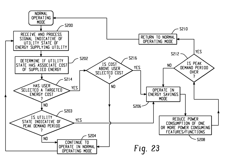
the user of the appliance operating in the energy savings mode.
[0063] The duration of time that the clothes dryer 110 operates in the energy
savings
mode may be determined by information in the energy signal 106. For example,
the energy
signal 106 may inform the clothes dryer 110 to operate in the energy savings
mode for a few
minutes or for one hour, at which time the appliance returns to normal
operation. Alternatively,
the energy signal 106 may be continuously transmitted by the utility provider,
or other signal
generating system, as long as it is determined that instantaneous load
reduction is necessary.
Once transmission of the signal 106 has ceased, the clothes dryer 110 returns
to normal operating
mode. In yet another embodiment, an energy signal may be transmitted to the
clothes dryer to
signal the clothes dryer to operate in the energy savings mode. A normal
operation signal may
then be later transmitted to the clothes dryer to signal the clothes dryer to
return to the normal
operating mode.
[0064] The operation of the clothes dryer 110 may vary as a function of a
characteristic
of the supplied energy, e.g., availability and/or price. Because some energy
suppliers offer what
is known as time-of-day pricing in their tariffs, price points could be tied
directly to the tariff
structure for the energy supplier. If real time pricing is offered by the
energy supplier serving the
site, this variance could be utilized to generate savings and reduce chain
demand. Another load
management program offered by energy supplier utilizes price tiers which the
utility manages
dynamically to reflect the total cost of energy delivery to its customers.
These tiers provide the
customer a relative indicator of the price of energy and are usually defined
as being LOW (level
1), MEDIUM (level 2), HIGH (level 3), and CRITICAL (level 4). These tiers are
shown in the
chart of Figure 24 to partially illustrate operation of the clothes dryer 110
in each pricing tier.
In the illustrative embodiment the appliance control response to the LOW and
MEDIUM tiers is
the same namely the appliance remains in the normal operating mode. Likewise
the response to
CA 02723083 2010-10-29
WO 2010/031029 PCT/US2009/056914
21
the HIGH and CRITICAL tiers is the same, namely operating the appliance in the
energy saving
mode. However, it will be appreciated that the controller could be configured
to implement a
unique operating mode for each tier which provides a desired balance between
compromised
performance and cost savings/energy savings. If the utility offers more than
two rate/cost
conditions, different combinations of energy saving control steps may be
programmed to provide
satisfactory cost savings/performance tradeoff. The operational and functional
adjustments
described above, and others, can be initiated and/or dependent upon the tiers.
For example, the
clothes dryer's highest heat setting selection can be prevented or `blocked'
from activating if the
pricing tier is at level 3 or 4. In one exemplary arrangement, the controller
resets the drying
temperature to a lower setting, i.e. using only the outer heating coil which
essentially uses one
half of the wattage when compared to full use of the heating coil. The display
118 can include, a
communication, for example, an audible and/or visual alert of pricing tier 3
and 4. Some
communication line with the utility can be established including, but not
limited to, the
communication arrangements hereinbefore described. In addition, the display
118 can provide
the actual cost of running the clothes dryer 110 in the selected mode of
operation, as well as,
maintain a running display of the present cost of energy. If the utility
offers more than two
rate/cost conditions, different combinations of energy saving control steps
may be programmed
to provide satisfactory cost savings/performance tradeoff.
[0065] The invention has been described with reference to the preferred
embodiments.
Obviously, modifications and alterations will occur to others upon reading and
understanding the
preceding detailed description. It is intended that the invention be construed
as including all
such modifications and alterations.