Note: Descriptions are shown in the official language in which they were submitted.
CA 02724341 2010-12-06
60412-4376
WIRELESS ENERGY TRANSFER, INCLUDING INTERFERENCE
ENHANCEMENT
BACKGROUND
The disclosure relates to wireless energy transfer. Wireless energy transfer
can
for example, be useful in such applications as providing power to autonomous
electrical
or electronic devices.
Radiative modes of omni-directional antennas (which work very well for
information transfer) are not suitable for such energy transfer, because a
vast majority of
energy is wasted into free space. Directed radiation modes, using lasers or
highly-
directional antennas, can be efficiently used for energy transfer, even for
long distances
(transfer distance LTRANs LDEv, where LDEv is the characteristic size of the
device and/or
the source), but require existence of an uninten-uptible line-of-sight and a
complicated
tracking system in the case of mobile objects. Some transfer schemes rely on
induction,
but are typically restricted to very close-range (LTRANY(LDEv) or low power (--
-mW) energy
transfers.
The rapid development of autonomous electronics of recent years (e.g. laptops,
cell-phones, house-hold robots, that all typically rely on chemical energy
storage) has led
to an increased need for wireless energy transfer.
1
CA 02724341 2010-12-06
60412-4376
SUMMARY
Efficient wireless energy-transfer between two resonant objects can
be achieved at mid-range distances, provided these resonant objects are
designed to operate in the 'strong-coupling' regime. We describe an
implementation of a method to increase the efficiency of energy-transfer or to
suppress the power radiated, which can be harmful or a cause of interference
to
other communication systems, by utilizing destructive interference between the
radiated far-fields of the resonant coupled objects. 'Strong-coupling' is a
necessary condition for efficient energy-transfer, in the absence of far-field
interference. 'Strong-coupling' can be demonstrated in the case of realistic
systems: self-resonant conducting coils, capacitively-loaded conducting coils,
inductively-loaded conducting rods and dielectric disks, all bearing high-Q
electromagnetic resonant modes. Also, an analytical model can be developed to
take far-field interference into account for wireless energy-transfer systems.
The
analytical model can be used to demonstrate the efficiency enhancement and
radiation suppression, in the presence of interference. In an example
implementation, we describe improved performance based on the above
principles in the case of two realistic systems: capacitively-loaded
conducting coils
and dielectric disks, both bearing high-Q electromagnetic resonant modes and
far-field interference.
According to an aspect, there is provided an apparatus for use in
wireless energy transfer, the apparatus comprising: a first resonator
structure
configured for energy transfer with a second resonator structure over a
distance D,
wherein the energy transfer is mediated by evanescent-tail coupling of a
resonant
field of the first resonator structure and a resonant field of the second
resonator
structure, with a coupling factor k, wherein said resonant field of the first
resonator
structure has a resonance angular frequency co, , a resonance frequency-width
F1,
and a resonance quality factor Q1= co, /2F, , and is radiative in the far
field, with an
associated radiation quality factor 0
I,rad ,
and said resonant field of the second
resonator structure has a resonance angular frequency co2, a resonance
frequency-width F2, and a resonance quality factor Q2 = (02 /2F2, and is
radiative in
2
CA 02724341 2010-12-06
60412-4376
the far field, with an associated radiation quality factor 0
Q2, wherein an
absolute value of a difference of said angular frequencies col and co2 is
smaller than
broader of said resonant widths F, and F2 and an average resonant angular
frequency is defined as coo = Vcoico2 , corresponding to an average resonant
wavelength 2 = 27-cc./ w0, where c is the speed of light in free space, and a
strong-
coupling factor being defined as U = kVQ1Q2 , wherein a power load is coupled
to
the second resonant structure with a coupling rate ic and is configured to
receive
from the second resonator structure a usable power, wherein U1 is defined as
KI /F2, further comprising a power generator coupled to the first resonant
structure
with a coupling rate Kg and is configured to drive the first resonator
structure at a
driving frequency f, corresponding to a driving angular frequency co = 27-t- f
, wherein
Ug is defined as Kg /F1, wherein the apparatus is configured to employ
destructive
interference between said radiative far fields of the resonant fields of the
first and
second resonator, with an interference factor had' to reduce a total amount of
radiation from the apparatus compared to an amount of radiation from the
apparatus in the absence of the interference, a strong-interference factor
being
defined as V = Vrad \AQI /Q1,rad)(Q2/Q2,rad)
According to an aspect, there is provided a method for wireless
energy transfer, the method comprising: providing a first resonator structure
configured for energy transfer with a second resonator structure over a
distance D,
wherein the energy transfer is mediated by evanescent-tail coupling of a
resonant
field of the first resonator structure and a resonant field of the second
resonator
structure, with a coupling factor k, wherein said resonant field of the first
resonator
structure has a resonance angular frequency col , a resonance frequency-width
F1,
and a resonance quality factor Q1 = col / 2F1 , and is radiative in the far
field, with an
associated radiation quality factor 0
Q1 and said resonant field of the second
resonator structure has a resonance angular frequency co2, a resonance
frequency-width F2 and a resonance quality factor Q2 = 02 / 2F2 , and is
radiative in
2a
CA 02724341 2010-12-06
60412-4376
the far field, with an associated radiation quality factor 0
.4-2,rad Q2, wherein an
absolute value of a difference of said angular frequencies col and 02 is
smaller
than broader of said resonant widths F1 and F2 and an average resonant angular
frequency is defined as coo = Vco1co2 , corresponding to an average resonant
wavelength 20 = 27rc / coo, where c is the speed of light in free space, and
the
strong-coupling factor is defined as U= kVQ1Q2 , wherein a power load is
coupled
to the second resonant structure with a coupling rate K, and is configured to
receive from the second resonator structure a usable power, wherein U, is
defined
as KIIF2, wherein a power generator coupled to the first resonant structure
with a
coupling rate Kg and is configured to drive the first resonator structure at a
driving
frequency f, corresponding to a driving angular frequency CO = 27rf, , wherein
Ug is
defined as Kg /F, , and employing destructive interference between said
radiative
far fields of the resonant fields of the first and second resonator, with an
interference factor had' to reduce a total amount of radiation from the first
and
second resonator compared to an amount of radiation from the first and second
resonator in the absence of the interference, a strong-interference factor
being
defined as V= V_
lad \i(Q1 Ql,rad ) (Q2 / Q2,rad
In an aspect, an apparatus for use in wireless energy transfer includes
a first resonator structure configured for energy transfer with a second
resonator
structure, over a distance D larger than a characteristic size L1 of said
first resonator
structure and larger than a characteristic size L2 of said second resonator
structure.
The energy transfer has a rate i and is mediated by evanescent-tail coupling
of a
resonant field of the first resonator structure and a resonant field of the
second
resonator structure. The resonant field of the first resonator structure has a
resonance angular frequency col , a resonance frequency-width F1, and a
resonance quality factor Q1= col /2F1 at least larger than 300, and the said
resonant
field of the second resonator structure has a resonance angular frequency w2,
a
resonance frequency-width F2 and a resonance quality factor Q2 = CO2 /2F2 at
least
2b
CA 02724341 2010-12-06
60412-4376
larger than 300. The absolute value of the difference of said angular
frequencies
N, and c02 is smaller than the broader of said resonant widths F, and
2c
CA 02724341 2010-11-12
WO 2009/140506
PCT/US2009/043970
F2 , and the quantity lc/ 0 -',/-'2. is at least larger than 20. The apparatus
also includes a
power supply coupled to the first structure and configured to drive the first
resonator
structure or the second resonator structure at an angular frequency away from
the
resonance angular frequencies and shifted towards a frequency corresponding to
an odd
normal mode for the resonator structures to reduce radiation from the
resonator structures
by destructive far-field interference.
In some examples, the power supply is configured to drive the first resonator
structure or the second resonator structure at the angular frequency away from
the
resonance angular frequencies and shifted towards the frequency corresponding
to an odd
normal mode for the resonator structures to substantially suppress radiation
from the
resonator structures by destructive far-field interference.
In an aspect, a method for wireless energy transfer involves a first resonator
structure configured for energy transfer with a second resonator structure,
over a distance
D larger than a characteristic size L1 of said first resonator structure and
larger than a
characteristic size L2 of said second resonator structure, wherein the energy
transfer has a
rate ic and is mediated by evanescent-tail coupling of a resonant field of the
first
resonator structure and a resonant field of the second resonator structure,
said resonant
field of the first resonator structure has a resonance angular frequency cot,
a resonance
frequency-width 115 and a resonance quality factor Q1 = co, / 2F, at least
larger than 300,
and said resonant field of the second resonator structure has a resonance
angular
frequency w25 a resonance frequency-width F2, and a resonance quality factor
Q2 = W2 / 2F2 at least larger than 300, the absolute value of the difference
of said angular
frequencies co, and w2 is smaller than the broader of said resonant widths F,
and F2,
and the quantity ic / I\ -',/-'2. is at least larger than 20. The method
includes driving the
first resonator structure or the second resonator structure at an angular
frequency away
from the resonance angular frequencies and shifted towards a frequency
corresponding to
an odd normal mode for the resonator structures to reduce radiation from the
resonator
structures by destructive far-field interference.
3
CA 02724341 2010-11-12
WO 2009/140506
PCT/US2009/043970
In some examples, the first resonator structure or the second resonator
structure is
driven at the angular frequency away from the resonance angular frequencies
and shifted
towards the frequency corresponding to an odd normal mode for the resonator
structures
to substantially suppress radiation from the resonator structures by
destructive far-field
interference.
In an aspect, an apparatus for use in wireless energy transfer includes a
first
resonator structure configured for energy transfer with a second resonator
structure, over
a distance D larger than a characteristic size L1 of said first resonator
structure and larger
than a characteristic size L2 of said second resonator structure. The energy
transfer has a
rate ic and is mediated by evanescent-tail coupling of a resonant field of the
first
resonator structure and a resonant field of the second resonator structure.
The resonant
field of the first resonator structure has a resonance angular frequency w1, a
resonance
frequency-width Fi , and a resonance quality factor Q1 = col / 2Fi at least
larger than 300,
and the resonant field of the second resonator structure has a resonance
angular frequency
w2, a resonance frequency-width F2, and a resonance quality factor Q2 = (D2 /
2F2 at
least larger than 300. The absolute value of the difference of said angular
frequencies col
and w2 is smaller than the broader of said resonant widths Fi and F2, and the
quantity
lc/ VF1F2 is at least larger than 20. For a desired range of the distances D,
the resonance
angular frequencies for the resonator structures increase transmission
efficiency T by
accounting for radiative interference, wherein the increase is relative to a
transmission
efficiency T calculated without accounting for the radiative interference.
In some examples, the resonance angular frequencies for the resonator
structures
are selected by optimizing the transmission efficiency T to account for both a
resonance
quality factor U and an interference factor V.
In an aspect, a method involves designing a wireless energy transfer
apparatus,
the apparatus including a first resonator structure configured for energy
transfer with a
second resonator structure, over a distance D larger than a characteristic
size L1 of said
first resonator structure and larger than a characteristic size L2 of said
second resonator
structure, wherein the energy transfer has a rate ic and is mediated by
evanescent-tail
4
CA 02724341 2010-11-12
WO 2009/140506
PCT/US2009/043970
coupling of a resonant field of the first resonator structure and a resonant
field of the
second resonator structure, wherein said resonant field of the first resonator
structure has
a resonance angular frequency w1, a resonance frequency-width Fi , and a
resonance
quality factor Q1 = (Di / 2Fi at least larger than 300, and said resonant
field of the second
resonator structure has a resonance angular frequency w2, a resonance
frequency-width
F2 , and a resonance quality factor Q2 = (D2 / 2F2 at least larger than 300,
wherein the
absolute value of the difference of said angular frequencies col and w2 is
smaller than the
broader of said resonant widths Fi and F2, and the quantity ic / VF1F2 is at
least larger
than 20. The method includes selecting the resonance angular frequencies for
the
resonator structures to substantially optimize the transmission efficiency by
accounting
for radiative interference between the resonator structures.
In some examples, the resonance angular frequencies for the resonator
structures
are selected by optimizing the transmission efficiency T to account for both a
resonance
quality factor Uand an interference factor V.
In an aspect, an apparatus for use in wireless energy transfer includes a
first
resonator structure configured for energy transfer with a second resonator
structure over a
distance D. The energy transfer is mediated by evanescent-tail coupling of a
resonant
field of the first resonator structure and a resonant field of the second
resonator structure,
with a coupling factor k. The resonant field of the first resonator structure
has a
resonance angular frequency wi, a resonance frequency-width Fi, and a
resonance
quality factor Q1 = (Di / 2Fi, and is radiative in the far field, with an
associated radiation
quality factor Qi,rad Q1, and the resonant field of the second resonator
structure has a
resonance angular frequency w25 a resonance frequency-width F2, and a
resonance
quality factor Q2 = (D2 / 2F 2 5 and is radiative in the far field, with an
associated radiation
quality factor Q2,rad Q2. An absolute value of a difference of said angular
frequencies
col and w2 is smaller than broader of said resonant widths Fl and F2, and an
average
resonant angular frequency is defined as co, = Voico25 corresponding to an
average
resonant wavelength k = 27-cc / wo, where c is the speed of light in free
space, and a
CA 02724341 2010-11-12
WO 2009/140506
PCT/US2009/043970
strong-coupling factor being defined as U = kSJQlQ2 . The apparatus is
configured to
employ interference between said radiative far fields of the resonant fields
of the first and
second resonator, with an interference factor "ad' to reduce a total amount of
radiation
from the apparatus compared to an amount of radiation from the apparatus in
the absence
of interference, a strong-interference factor being defined as
V Vrad '\1( Q1 / Ql,rad )( Q2 / Q2,rad ) =
The following are examples within the scope of this aspect.
The apparatus has 01 /
¨ ¨0
1,rad 0.01 and 02 ¨0
¨2,r ad 0.01. The apparatus has
Qi Ql,rad 0.1 and 0 / 0
0.1. The apparatus has D I k larger than 0.001 and the
strong-interference factor V is larger than 0.01. The apparatus has D I k
larger than
0.001 and the strong-interference factor V is larger than 0.1. The apparatus
includes the
second resonator structure.
During operation, a power generator is coupled to one of the first and second
resonant structure, with a coupling rate Kg , and is configured to drive the
resonator
structure, to which it is coupled, at a driving frequencyf, corresponding to a
driving
angular frequency w = 27-cf, , wherein Ug is defined as Kg I F1, if the power
generator is
coupled to the first resonator structure and defined as Kg I F2, if the power
generator is
coupled to the second resonator structure. The driving frequency is different
from the
resonance frequencies of the first and second resonator structures and is
closer to a
frequency corresponding to an odd normal mode of the system of the two
resonator
structures, wherein the detuning of the first resonator from the driving
frequency is
defined as D1 = (co ¨ col )/ 11 and the detuning of the second resonator
structure from the
driving frequency is defined as D2 = (CD ¨ CO2) / F2 .
DI is approximately equal to UVrad and D2 is approximately equal to UVrad Ug
is chosen to maximize the ratio of the energy-transfer efficiency to the
radiation
efficiency. Ug is approximately equal to Nil + U2 ¨ avr2du2 v2 2VVrad . fis
at least
larger than 100 kHz and smaller than 500MHz. f is at least larger than 1MHz
and smaller
6
CA 02724341 2010-11-12
WO 2009/140506
PCT/US2009/043970
than 50MHz. The apparatus further includes the power generator. During
operation, a
power load is coupled to the resonant structure to which the power generator
is not
coupled, with a coupling rate K1, and is configured to receive from the
resonator
structure, to which it is coupled, a usable power, wherein U1 is defined as Ki
/ F1, if the
power load is coupled to the first resonator structure and defined as Ki / F2,
if the power
load is coupled to the second resonator structure. U1 is chosen to maximize
the ratio of
the energy-transfer efficiency to the radiation efficiency. The driving
frequency is
different from the resonance frequencies of the first and second resonator
structures and
is closer to a frequency corresponding to an odd normal mode of the system of
the two
resonator structures, wherein the detuning of the first resonator from the
driving
frequency is defined as D1 = (co ¨ wi )/ F1 and is approximately equal to
UVrad , and the
detuning of the second resonator structure from the driving frequency is
defined as
D2 = (6)¨ W2 )/ "2 and is approximately equal to UVrad , and U1 is
approximately equal to
Vi+ __ u2 vra2du2 v2 2VVrad .
At least one of the first and second resonator structures comprises a
capacitively
loaded loop or coil of at least one of a conducting wire, a conducting Litz
wire, and a
conducting ribbon. The characteristic size of said loop or coil is less than
30 cm and the
width of said conducting wire or Litz wire or ribbon is less than 2cm. The
characteristic
size of said loop or coil is less than lm and the width of said conducting
wire or Litz wire
or ribbon is less than 2cm.
The apparatus further includes a feedback mechanism for maintaining the
resonant frequency of one or more of the resonant objects. The feedback
mechanism
comprises an oscillator with a fixed driving frequency and is configured to
adjust the
resonant frequency of the one or more resonant objects to be detuned by a
fixed amount
with respect to the fixed frequency.
In an aspect, an apparatus for use in wireless energy transfer includes a
first
resonator structure configured for energy transfer with a second resonator
structure over a
distance D. The energy transfer is mediated by evanescent-tail coupling of a
resonant
field of the first resonator structure and a resonant field of the second
resonator structure,
7
CA 02724341 2010-12-06
60412-4376
with a coupling factor k. The resonant field of the first resonator structure
has a
resonance angular frequency coõ a resonance frequency-width Fõ and a resonance
quality factor Q, = co, / 2F1, and is radiative in the far field, with an
associated radiation
quality factor Q,,,ad Q1, and the resonant field of the second resonator
structure has a
resonance angular frequency w7, a resonance frequency-width F and a resonance
quality factor Q2 = (02 I 21'
2, and is radiative in the far field, with an associated radiation
quality factor Q2,rad ?_ Q2. An absolute value of a difference of said angular
frequencies
co, and co2 is smaller than the broader of said resonant widths F, and F2 and
an average
resonant angular frequency is defined as co, = Vco1co2 , corresponding to an
average
resonant wavelength A, =2,7-cc I coo, where c is the speed of light in free
space, and a
strong-coupling factor is defined as U = kVQ1Q2 . The apparatus is configured
to employ
destructive interference between said radiative far fields of the resonant
fields of the first and
second resonator, with an interference factor Vrad, to increase efficiency of
energy transfer for the
apparatus compared to efficiency for the apparatus in the absence of
interference, the
strong-interference factor being defined as V = Vrad / ,rad ) (Q2 /
Q2,rad).
The following are examples within the scope of this aspect.
The apparatus has Q, / Q,,rad 0.05 and Q2 /Q2 0.05. The apparatus has
Qi I 0.5 and Q2 /Q2 0.5. The apparatus has DI A, larger than 0.01 and
the
strong-interference factor V is larger than 0.05. The apparatus has D / larger
than 0.01
and the strong-interference factor V is larger than 0.5. The apparatus further
includes the
second resonator structure.
During operation, a power generator is coupled to one of the first and second
resonant structure, with a coupling rate Kg , and is configured to drive the
resonator
structure, to which it is coupled, at a driving frequency f, corresponding to
a driving
angular frequency co = 271-f , wherein Ug is defined as Kg Irt, if the power
generator is
coupled to the first resonator structure and defined as Kg I F2, if the power
generator is
coupled to the second resonator structure. The driving frequency is different
from the
8
CA 02724341 2010-11-12
WO 2009/140506
PCT/US2009/043970
resonance frequencies of the first and second resonator structures and is
closer to a
frequency corresponding to an odd normal mode of the system of the two
resonator
structures, wherein the detuning of the first resonator from the driving
frequency is
defined as D1 = (co ¨ wi )/ F1 and the detuning of the second resonator
structure from the
driving frequency is defined as D2 = (w ¨ CD2 ) /
D1 is approximately equal to UV and D2 is approximately equal to UV. (_ I , is
chosen to maximize the energy-transfer efficiency. Ug is approximately equal
to
\Al + U2)(1¨ 1/2) . f is at least larger than 100 kHz and smaller than 500MHz.
f is at
least larger than 1MHz and smaller than 50MHz. The apparatus further includes
the
power generator.
During operation, a power load is coupled to the resonant structure to which
the
power generator is not coupled, with a coupling rate K i , and is configured
to receive from
the resonator structure, to which it is coupled, a usable power, wherein U1 is
defined as
Ki / F1, if the power load is coupled to the first resonator structure and
defined as Ki I F 2 5
if the power load is coupled to the second resonator structure. U1 is chosen
to maximize
the energy-transfer efficiency. The driving frequency is different from the
resonance
frequencies of the first and second resonator structures and is closer to a
frequency
corresponding to an odd normal mode of the system of the two resonator
structures,
wherein the detuning of the first resonator from the driving frequency is
defined as
D1 = (co ¨ col )/ Fi and is approximately equal to UV, and the detuning of the
second
resonator structure from the driving frequency is defined as D2 = (w ¨ CD2 ) /
F 2 and is
approximately equal to UV, and U1 is approximately equal to \Al + U2)(1¨ v2).
At least one of the first and second resonator structures comprises a
capacitively
loaded loop or coil of at least one of a conducting wire, a conducting Litz
wire, and a
conducting ribbon. The characteristic size of said loop or coil is less than
30 cm and the
width of said conducting wire or Litz wire or ribbon is less than 2cm. The
characteristic
size of said loop or coil is less than lm and the width of said conducting
wire or Litz wire
9
CA 02724341 2010-11-12
WO 2009/140506
PCT/US2009/043970
or ribbon is less than 2cm. The apparatus includes a feedback mechanism for
maintaining the resonant frequency of one or more of the resonant objects. The
feedback
mechanism comprises an oscillator with a fixed driving frequency and is
configured to
adjust the resonant frequency of the one or more resonant objects to be
detuned by a fixed
amount with respect to the fixed frequency. The feedback mechanism is
configured to
monitor an efficiency of the energy transfer, and adjust the resonant
frequency of the one
or more resonant objects to maximize the efficiency. The resonance angular
frequencies
for the resonator structures are selected to optimize the energy-transfer
efficiency by
accounting for both the strong-coupling factor U and the strong-interference
interference
factor V.
In an aspect, a method for wireless energy transfer includes providing a first
resonator structure configured for energy transfer with a second resonator
structure over a
distance D, wherein the energy transfer is mediated by evanescent-tail
coupling of a
resonant field of the first resonator structure and a resonant field of the
second resonator
structure, with a coupling factor k, wherein said resonant field of the first
resonator
structure has a resonance angular frequency w1, a resonance frequency-width F,
, and a
resonance quality factor Q1 = co, / 2F,, and is radiative in the far field,
with an associated
radiation quality factor Qi,rad Q1, and resonant field of the second resonator
structure
has a resonance angular frequency w2, a resonance frequency-width F2, and a
resonance
quality factor Q2 = (D2 / 2F 2 , and is radiative in the far field, with an
associated radiation
quality factor Q2,rad Q2, wherein an absolute value of a difference of said
angular
frequencies co, and co2 is smaller than broader of said resonant widths F, and
F2, and an
average resonant angular frequency is defined as co, = Vcoico2 5 corresponding
to an
average resonant wavelength k = 27-i-c / co, , where c is the speed of light
in free space,
and the strong-coupling factor is defined as U =kVQQ2 5 and employing
interference
between said radiative far fields of the resonant fields of the first and
second resonator,
with an interference factor 'ad' to reduce a total amount of radiation from
the first and
second resonator compared to an amount of radiation from the first and second
resonator
in the absence of interference, a strong-interference factor being defined as
CA 02724341 2010-12-06
60412-4376
¨ -
V = Vrad 4(Qt 0 )(Q2 02,rad
The following are examples within the scope of this aspect.
The method has a I QI,rad 0.01 and Q2 / Q2d 0.01. During operation, a power
generator is coupled to one of the first and second resonant structure and is
configured to
drive the resonator structure, to which it is coupled, at a driving
frequencyf,
corresponding to a driving angular frequency co = 2R-f, wherein the driving
frequency is different from the resonance frequencies of the first and second
resonator
structures and is closer to a frequency corresponding to an odd normal mode of
the
system of the two resonator structures. During operation, a power load is
coupled to the
resonant structure to which the power generator is not coupled and is
configured to
receive from the resonator structure, to which it is coupled, a usable power.
In an aspect, a method for wireless energy transfer includes providing a first
resonator
structure configured for energy transfer with a second resonator structure
over a distance
D, wherein the energy transfer is mediated by evanescent-tail coupling of a
resonant field
of the first resonator structure and a resonant field of the second resonator
structure, with
a coupling factor k, wherein said resonant field of the first resonator
structure has a
resonance angular frequency col , a resonance frequency-width , and a
resonance
quality factor a = col I 2F1, and is radiative in the far field, with an
associated radiation
quality factor Qi,rad Q1, and said resonant field of the second resonator
structure has a
resonance angular frequency co2, a resonance frequency-width F2 and a
resonance
quality factor a = co2 I 2F2, and is radiative in the far field, with an
associated radiation
quality factor Q2,rad Q2, wherein an absolute value of the difference of said
angular
frequencies co, and 0o2 is smaller than the broader of said resonant widths F1
and F2 ,and
an average resonant angular 'frequency is defined as coo =ctr)702 ,
corresponding to an
average resonant wavelength 20 = 27z-c I coo , where c is the speed of light
in free space,
and the strong-coupling factor is defined as U = kVaQ2 , and employing
destructive
interference between said radiative far fields of the resonant fields of the
first and second resonator,
with an interference factor V,,,d , to increase efficiency of energy transfer
between the first
11
CA 02724341 2010-12-06
60412-4376
and second resonator compared to efficiency of energy transfer between the
first and second
resonator in the absence of the interference, a strong-interference factor
being defined
as V = \Kg 0
t,rad )(Q21 Q2,rad ) =
The following are examples within the scope of this aspect.
The method has sa / Qi,rad 0.05 and Q2 / Q2,rad 0.05. During operation, a
power generator is coupled to one of the first and second resonant structure
and is
configured to drive the resonator structure, to which it is coupled, at a
driving frequency
f, corresponding to a driving angular frequency co = 27cf, , wherein the
driving
frequency is different from the resonance frequencies of the first and second
resonator
structures and is closer to a frequency corresponding to an odd normal mode of
the
system of the two resonator structures. During operation, a power load is
coupled to the
resonant structure to which the power generator is not coupled and is
configured to
receive from the resonator structure, to which it is coupled, a usable power.
The
resonance angular frequencies for the resonator structures are selected to
optimize the
energy-transfer efficiency by accounting for both the strong-coupling factor U
and the
strong-interference interference factor V.
Various examples may include any of the above features, alone or in
combination.
Other features, objects, and advantages of the disclosure will be apparent
from the
following detailed description.
BRIEF DESCRIPTION OF THE DRAWINGS
Fig. 1 shows a schematic of an example wireless energy transfer scheme.
Figs. 2(a)-(b) show the efficiency of power transmission rip for (a) U = 1 and
(b)
U = 3, as a function of the frequency detuning Do and for different values of
the loading
rate U0. =
Fig. 2(c) shows the optimal (for zero detuning and under conditions of
impedance
matching) efficiency for energy transfer riE* and power transmission rip., as
a function of
the coupling-to-loss figure-of-merit U.
Fig. 3 shows an example of a self-resonant conducting-wire coil.
12 =
CA 02724341 2010-11-12
WO 2009/140506
PCT/US2009/043970
Fig. 4 shows an example of a wireless energy transfer scheme featuring two
self-
resonant conducting-wire coils
Fig. 5 is a schematic of an experimental system demonstrating wireless energy
transfer.
Fig. 6 shows a comparison between experimental and theoretical results for the
coupling rate of the system shown schematically in Fig. 5.
Fig. 7 shows a comparison between experimental and theoretical results for the
strong-coupling factor of the system shown schematically in Fig. 5.
Fig. 8 shows a comparison between experimental and theoretical results for the
power-transmission efficiency of the system shown schematically in Fig. 5.
Fig. 9 shows an example of a capacitively loaded conducting-wire coil, and
illustrates the surrounding field.
Fig. 10 shows an example wireless energy transfer scheme featuring two
capacitively loaded conducting-wire coils, and illustrates the surrounding
field.
Fig. 11 illustrates an example circuit model for wireless energy transfer.
Fig. 12 shows the efficiency, total (loaded) device Q, and source and device
currents, voltages and radiated powers (normalized to 1Watt of output power to
the load)
as functions of the resonant frequency, for a particular choice of source and
device loop
dimensions, wp and Ns and different choices of Nd=1,2,3,4,5,6,10 (red, green,
blue,
magenta, yellow, cyan, black respectively).
Fig.13 shows the efficiency, total (loaded) device Q, and source and device
currents, voltages and radiated powers (normalized to 1Watt of output power to
the load)
as functions of frequency and wp for a particular choice of source and device
loop
dimensions, and number of turns Ns and Nd.
Fig. 14 shows an example of an inductively-loaded conducting-wire coil.
Fig. 15 shows (a) an example of a resonant dielectric disk, and illustrates
the
surrounding field and (b) a wireless energy transfer scheme featuring two
resonant
dielectric disks, and illustrates the surrounding field.
Figs. 16(a)-(b) show the efficiency of power transmission rip for (a) U = 1, V
=
0.5 and (b) U = 3, V = 0.5, as a function of the frequency detuning Do and for
different
values of the loading rate Uo. (The dotted lines show, for comparison, the
results when
13
CA 02724341 2010-11-12
WO 2009/140506
PCT/US2009/043970
there is no interference, as shown in Fig.2(a)-(b).) and Figs. 16(c)-(d) show
the optimal
(for optimal detuning and under conditions of impedance matching) efficiency
for energy
transfer (only in (c)) and power transmission, as a function of the strong-
coupling factor
U and the strong-interference factor V.
Fig. 17 shows coupled-mode theory (CMT) results for (a) the coupling factor k
and (b) the strong-coupling factor U as a function of the relative distance
D/r between
two identical capacitively-loaded conducting single-turn loops, for three
different
dimensions of the loops. Note that, for conducting material, copper (a = 5
.998107S/m )
was used.
Fig. 18 shows AT results for the interference factor 'ad as a function of the
distance D (normalized to the wavelength 2) between two capacitively-loaded
conducting loops.
Fig. 19 shows CMT results for the strong-coupling factor U and AT results for
the interference factor Vrad and strong-interference factor V as a function of
the resonant
eigenfrequency of two identical capacitively-loaded conducting single-turn
loops with
r = 30cm and a = 2cm , at a relative distance D I r = 5 between them. Note
that, for
conducting material, copper (a =5.998.107S/m ) was used.
Fig. 20 shows the power-transmission efficiency as a function of the resonant
eigenfrequency of two identical capacitively-loaded conducting single-turn
loops. Results
for two different loop dimensions are shown and for two relative distances
between the
identical loops. For each loops dimension and distance, four different cases
are examined:
without far-field interference (dotted), with far-field interference but no
driving-
frequency detuning (dashed) and with driving-frequency detuning to maximize
either the
efficiency (solid) or the ratio of efficiency over radiation (dash-dotted).
Fig. 21 shows the driving-frequency detunings required in the presence of far-
field interference as a function of the resonant eigenfrequency of two
identical
capacitively-loaded conducting single-turn loops of Fig. 20 to maximize either
the
efficiency (solid) or the ratio of efficiency over radiation (dash-dotted).
Fig. 22(a) shows the resonant eigenfrequencies f,_, and fr, , where the strong-
coupling factor U and the power-transmission efficiency q peak respectively,
as a
14
CA 02724341 2010-11-12
WO 2009/140506
PCT/US2009/043970
function of the relative distance D I r between two identical loops with r =
30cm and
a = 2cm .
Fig. 22(b) illustrates the strong-coupling factor U and the strong-
interference
factor V as a curve in the U ¨V plane, parametrized with the relative distance
D I r
between the two loops, for the cases with interference and eigenfrequency fr,
(solid),
with interference and eigenfrequency f,_, (dashed), and without interference
and
eigenfrequency I', (dotted).
Fig. 22(c) shows the efficiency enhancement ratio of the solid curve in Fig.
22(b)
relative to the dashed and dotted curves in Fig. 22(b).
Fig. 23 shows the radiation efficiency as a function of the resonant
eigenfrequency of two identical capacitively-loaded conducting single-turn
loops. Results
for two different loop dimensions are shown and for two relative distances
between the
identical loops. For each loops dimension and distance, four different cases
are examined:
without far-field interference (dotted), with far-field interference but no
driving-
frequency detuning (dashed) and with driving-frequency detuning to maximize
either the
efficiency (solid) or the ratio of efficiency over radiation (dash-dotted).
Fig. 24 shows CMT results for (a) the coupling factor k and (b) the strong-
coupling factor U, for three different m values of subwavelength resonant
modes of two
same dielectric disks at distance D I r = 5 (and also a couple more distances
for m = 2),
when varying their c in the range 250 Ã 35. Note that disk-material loss-
tangent
tan g = 6.10-6c ¨2.10-4 was used. (c) Relative U error between CMT and
numerical
FEFD calculations of part (b).
Fig. 25 shows Antenna Theory (AT) results for (a) the normalized interference
term 2A /ct.\/co2 and (b) magnitude of the strong-interference factor IV , as
a function of
frequency, for the exact same parameters as in Fig.24. (c) Relative V error
between AT
and numerical FEFD calculations of part (b).
Fig. 26 shows results for the overall power transmission as a function of
frequency, for the same set of resonant modes and distances as in Figs.24 and
25, based
on the predictions including interference (solid lines) and without
interference, just from
U (dotted lines).
CA 02724341 2010-11-12
WO 2009/140506
PCT/US2009/043970
Fig. 27 (a) shows the frequencies f,_, and fr, , where the strong-coupling
factor U
and the power-transmission efficiency 77 are respectively maximized, as a
function of the
transfer distance between the m = 2 disks of Fig. 15. Fig. 27(b) shows the
efficiencies
achieved at the frequencies of (a) and, in inset, the enhancement ratio of the
optimal (by
definition) efficiency for fn versus the achievable efficiency at I', . Fig.
27(c) shows the
D -parametrized path of the transmission efficiency for the frequency choices
of (a) on
the U ¨ V efficiency map.
Fig. 28 shows results for the radiation efficiency as a function of the
transfer
distance at resonant frequency fu , when the operating frequency is detuned
(solid line),
when it is not (dashed line), and when there is no interference whatsoever
(dotted line). In
the inset, we show the corresponding radiation suppression factors.
Figs. 29(a)-(b) show schematics for frequency control mechanisms.
Figs. 30(a)-(c) illustrate a wireless energy transfer scheme using two
dielectric
disks in the presence of various extraneous objects.
DETAILED DESCRIPTION
1. Efficient energy-transfer by 'strongly coupled' resonances
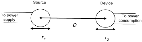
Fig. 1 shows a schematic that generally describes one example of the
invention, in
which energy is transferred wirelessly between two resonant objects. Referring
to Fig. 1,
energy is transferred, over a distance D, between a resonant source object
having a
characteristic size ri and a resonant device object of characteristic size r2.
Both objects
are resonant objects. The wireless non-radiative energy transfer is performed
using the
field (e.g. the electromagnetic field or acoustic field) of the system of two
resonant
objects.
The characteristic size of an object can be regarded as being equal to the
radius of
the smallest sphere which can fit around the entire object. The characteristic
thickness of
an object can be regarded as being, when placed on a flat surface in any
arbitrary
configuration, the smallest possible height of the highest point of the object
above a flat
surface. The characteristic width of an object can be regarded as being the
radius of the
16
CA 02724341 2010-11-12
WO 2009/140506
PCT/US2009/043970
smallest possible circle that the object can pass through while traveling in a
straight line.
For example, the characteristic width of a cylindrical object is the radius of
the cylinder.
It is to be understood that while two resonant objects are shown in the
example of
Fig. 1, and in many of the examples below, other examples can feature three or
more
resonant objects. For example, in some examples, a single source object can
transfer
energy to multiple device objects. In some examples, energy can be transferred
from a
first resonant object to a second resonant object, and then from the second
resonant object
to a third resonant object, and so forth.
Initially, we present a theoretical framework for understanding non-radiative
wireless energy transfer. Note however that it is to be understood that the
scope of the
invention is not bound by theory.
Different temporal schemes can be employed, depending on the application, to
transfer energy between two resonant objects. Here we will consider two
particularly
simple but important schemes: a one-time finite-amount energy-transfer scheme
and a
continuous finite-rate energy-transfer (power) scheme.
1.1 Finite-amount energy-transfer efficiency
Let the source and device objects be 1, 2 respectively and their resonance
eigemodes, which we will use for the energy exchange, have angular frequencies
w12,
frequency-widths due to intrinsic (absorption, radiation etc.) losses F and
(generally)
vector fields F1,2 (r), normalized to unity energy. Once the two resonant
objects are
brought in proximity, they can interact and an appropriate analytical
framework for
modeling this resonant interaction is that of the well-known coupled-mode
theory (CMT).
In this picture, the field of the system of the two resonant objects 1, 2 can
be
approximated by F (r, t) = a1 (t)F1 (r)+ a2 (t)F2 (r), where a1,2 (t) are the
field
amplitudes, with la1,2 (t)21 equal to the energy stored inside the object 1, 2
respectively,
due to the normalization. Then, using e- 1" time dependence, the field
amplitudes can be
shown to satisfy, to lowest order:
17
CA 02724341 2010-11-12
WO 2009/140506
PCT/US2009/043970
d
- (t)= (t)+iiciai (t)+iici2a2 (t)
dt
(1)
d ,
¨a2 (t)= ¨4(02 ¨iF2)a2 (t)+iic2iai (t)+iic22a2 (t)
dt
where K11,22 are the shifts in each object's frequency due to the presence of
the other,
which are a second-order correction and can be absorbed into the
eigenfrequencies by
setting C 1,2 ¨> W1,2 K1122, and Ki2,21 are the coupling coefficients, which
from the
reciprocity requirement of the system must satisfy /C21 /C12 ¨K.
The normal modes of the combined system are found, by substituting
[al (t), a2 (t)] = [Ai, A2] e-i't , to have complex frequencies
col + (02 Fi + F2 r ¨ W2 F -F 2
(7) _____________________________________ i 1 2 K.2
(2)
2 2 2 2 2
whose splitting we denote asE (.74 ¨ (7)_. Note that, at exact resonance col =
co2 and
for F1 = F2 , we get 6E = 2K.
Assume now that at time t = 0 the source object 1 has finite energy lai (0)12,
while
the device object has la2 (0)12 = 0. Since the objects are coupled, energy
will be
transferred from 1 to 2. With these initial conditions, Eqs.(1) can be solved,
predicting
the evolution of the device field-amplitude to be
a2 (t)
t \ ri+F2t
_________________________ = ¨2icsin e 2 . (3)
(0)1 SE 2
The energy-transfer efficiency will be 7/E I a2 (t)12/lai (0)12. Note that,
at exact
resonance col = co2 and in the special case F1 = F2 E Fo, Eq.(3) can be
written as
a2 (T)
_____________________________ = sin (UT).e-T
(4)
(0)1
where T E Fot and U = K/Fo.
18
CA 02724341 2010-11-12
WO 2009/140506
PCT/US2009/043970
In some examples, the system designer can adjust the duration of the coupling
t at
will. In some examples, the duration t can be adjusted to maximize the device
energy
(and thus efficiency TIE). Then, in the special case F1 = 2= Fo, it can be
inferred from
Eq.(4) that TIE is maximized for
T. = tan-1 U
(5)
U
resulting in an optimal energy-transfer efficiency
U i
2 tan-1 U
17,. r7, (T.) = 1+ u2 ____________ exp _______
U (6)
\ /
which is only a function of the coupling-to-loss ratio U = K/F0 and tends to
unity when
U >> 1, as depicted in Fig.2(c). In general, also for F1 # F2, the energy
transfer is nearly
perfect, when the coupling rate is much faster than all loss rates (K/F1,2 >>
1).
In a real wireless energy-transfer system, the source object can be connected
to a
power generator (not shown in Fig. 1), and the device object can be connected
to a power
consuming load (e.g. a resistor, a battery, an actual device, not shown in
Fig.1). The
generator will supply the energy to the source object, the energy will be
transferred
wirelessly and non-radiatively from the source object to the device object,
and the load
will consume the energy from the device object. To incorporate such supply and
consumption mechanisms into this temporal scheme, in some examples, one can
imagine
that the generator is very briefly but very strongly coupled to the source at
time t = 0 to
almost instantaneously provide the energy, and the load is similarly very
briefly but very
strongly coupled to the device at the optimal time t = t, to almost
instantaneously drain
the energy. For a constant powering mechanism, at time t = t, also the
generator can
again be coupled to the source to feed a new amount of energy, and this
process can be
repeated periodically with a period t*.
1.2 Finite-rate energy-transfer (power-transmission) efficiency
Let the generator be continuously supplying energy to the source object 1 at a
rate
Ki and the load continuously draining energy from the device object 2 at a
rate K2. Field
2
S ) +1 2 (t
amplitudes - , are then defined, so that Is 1,2 (t)1 1.s equal to the power
ingoing to
19
CA 02724341 2010-11-12
WO 2009/140506
PCT/US2009/043970
(for the + sign) or outgoing from (for the - sign) the object 1, 2
respectively, and the CMT
equations are modified to
d , \
¨ai V) = ¨i(oi
dt
¨d a2 (t)= -i(o2 -iF2)a2 (t)+iic2iai (t)+iic22a2 (t)-ic2a2 (t)
dt (7)
s 1 (t)=.\lai (t)-s1 (t)
s_2 (t)= V2Ta2(t)
where again we can set co1,2 -> (01,2 + K11,22 and K21 = K12 E IC=
Assume now that the excitation is at a fixed frequency co, namely has the form
s+1(t) = S_Fle-i'. Then the response of the linear system will be at the same
frequency,
namely a1,2(t) = AL2e-i" and s_1,2 (t) = S_1,2e i". By substituting these into
Eqs.(7),
-
using 61,2 E CO - coi,2, and solving the system, we find the field-amplitude
transmitted to
the load (S21 scattering-matrix element)
S-2 = 2iic ic
1 2
S -
21 - SA (Fi Ki - iC5; ) (F2 K2 - /.452 ) K2
(8)
2iUVU1U2
(1 U1-01)(1 U2 -iD2)+U2
and the field-amplitude reflected to the generator (S11 scattering-matrix
element)
c, SA (F1-K-1 -0102 K2-02)+1(2
L111 - c
L1+1 (F1 /C1 igl )(F2 /C2 1.82 ) Ic2
(9)
(1-U1-iD1)(1+U2-iD2)+U2
(1 U1-01)(1 U2-iD2)+U2
where D1,2 E 61,2/F1,29 U1,2 E K1,2 /F1,2 and U E IC/ I-1-'2. Similarly, the
scattering-
matrix elementsS12, S22 are given by interchanging 1 <-> 2 in Eqs.(8),(9) and,
as expected
from reciprocity, S21 = S12. The coefficients for power transmission
(efficiency) and
reflection and loss are respectively rip E 1S2112 = IS-212/ I S+112 and 1S1112
=
1S-112/1S+112 and 1- 1S2112 - 1S1112 = (2f11A112 + 2F21A212)/1S+112.
In practice, in some implementations, the parameters D1,2, U1,2 can be
designed
(engineered), since one can adjust the resonant frequencies co1,2 (compared to
the desired
CA 02724341 2010-11-12
WO 2009/140506
PCT/US2009/043970
operating frequency co) and the generator/load supply/drain rates K1,2. Their
choice can
target the optimization of some system performance-characteristic of interest:
In some examples, a goal can be to maximize the power transmission
(efficiency)
7/P E IS2112 of the system, so one would require
(10)
Since S21 (from Eq.(8)) is symmetric upon interchanging 1 2, the optimal
values for D1,2 (determined by Eqs.(10)) will be equal, namely D1 = D2 E Do,
and
similarly U1 = U2 E Uo. Then,
2iUU,
S21 ________________________________________
(1 Uo¨iDo)2 +U2 (11)
and from the condition rip' (DO= 0 we get that, for fixed values of U and Uo,
the
efficiency can be maximized for the following values of the symmetric detuning
D,= \1U2 ¨(1+U ,)2 , if U >1+ U,
0, if U 1+U0 (12)
which, in the case U > 1+ Uo, can be rewritten for the two frequencies at
which the
efficiency peaks as
WiF 2 W2F1 + 2N/F1F2 2 ______________
W+ = _____________________________ .N/K(F (F K
1 1 2 2,
Fi F2 Fi F2 (13)
whose splitting we denote as613 E (.74 ¨ (.7)_. Note that, at exact resonance
col = co2, and
for F1 = F2 E Fo and K1 = K2 E Ko, we get 613 = 2-11C2 ¨ (F0 + K0)2 < 6E,
namely the
transmission-peak splitting is smaller than the normal-mode splitting. Then,
by
substituting Do into rip from Eq.(12), from the condition rip' (Us) = 0 we get
that, for
fixed value of U, the efficiency can be maximized for
Eq (12)
= 1/1 U2 D=0
(14)
which is known as 'critical coupling' condition, whereas for U0 < Uo, the
system is
called `undercoupled' and for U0 > Uo* it is called `overcoupled'. The
dependence of
the efficiency on the frequency detuning Do for different values of U0
(including the
21
CA 02724341 2010-11-12
WO 2009/140506
PCT/US2009/043970
'critical-coupling' condition) are shown in Fig. 2(a,b). The overall optimal
power
efficiency using Eqs.(14) is
2
U . -1/ U
ih. 1.7,(D0.,(10.)= _______________ = __ 1
1+-µ1+u 2 , '
U0. +1 (15)
which is again only a function of the coupling-to-loss ratio U = KII.\-'2 and
tends to
unity when U >> 1, as depicted in Fig. 2(c).
In some examples, a goal can be to minimize the power reflection at the side
of
the generator IS1112 and the load IS22125 so one would then need
S11,22 0 (1-TUi -iDi)(1 U2 -iD2)+U2 =0,
(16)
The equations above present 'impedance matching' conditions. Again, the set of
these conditions is symmetric upon interchanging 1 <-* 2, so, by substituting
D1 = D2 E
Do and U1 = U2 E U0 into Eqs.(1 6), we get
(1 - iDo )2 - uo2 u2 05
(17)
from which we easily find that the values of Do and U0 that cancel all
reflections are
again exactly those in Eqs.(14).
It can be seen that, for this particular problem, the two goals and their
associated
sets of conditions (Eqs.(1 0) and Eqs.(1 6)) result in the same optimized
values of the intra-
source and intra-device parameters D1,25 U12. Note that for a lossless system
this would
be an immediate consequence of power conservation (Hermiticity of the
scattering
matrix), but this is not apparent for a lossy system.
Accordingly, for any temporal energy-transfer scheme, once the parameters
specific only to the source or to the device (such as their resonant
frequencies and their
excitation or loading rates respectively) have been optimally designed, the
efficiency
monotonically increases with the ratio of the source-device coupling-rate to
their loss
rates. Using the definition of a resonance quality factor Q = co/2F and
defining by
analogy the coupling factor k E 1 /QK E 21c/Vco1co2, it is therefore exactly
this ratio
22
CA 02724341 2010-11-12
WO 2009/140506
PCT/US2009/043970
U = ____________________________
K
= 'CAI (21(22
1.% -'ii-'2 (18)
that has been set as a figure-of-merit for any system under consideration for
wireless
energy-transfer, along with the distance over which this ratio can be achieved
(clearly, U
will be a decreasing function of distance). The desired optimal regime U > 1
is called
'strong-coupling' regime and it is a necessary and sufficient condition for
efficient
energy-transfer. In particular, for U > 1 we get, from Eq.(15), rip, > 17%,
large enough
for practical applications. The figure-of-merit U is called the strong-
coupling factor. We
will further show how to design systems with a large strong-coupling factor.
To achieve a large strong-coupling factor U, in some examples, the energy-
transfer application preferably uses resonant modes of high quality factors Q,
corresponding to low (i.e. slow) intrinsic-loss rates F. This condition can be
satisfied by
designing resonant modes where all loss mechanisms, typically radiation and
absorption,
are sufficiently suppressed.
This suggests that the coupling be implemented using, not the lossy radiative
far-
field, which should rather be suppressed, but the evanescent (non-lossy)
stationary near-
field. To implement an energy-transfer scheme, usually more appropriate are
finite
objects, namely ones that are topologically surrounded everywhere by air, into
where the
near field extends to achieve the coupling. Objects of finite extent do not
generally
support electromagnetic states that are exponentially decaying in all
directions in air
away from the objects, since Maxwell's Equations in free space imply that
k2=w2/c2 ,
where k is the wave vector, 03 the angular frequency, and c the speed of
light, because of
which one can show that such finite objects cannot support states of infinite
Q, rather
there always is some amount of radiation. However, very long-lived (so-called
"high-Q")
states can be found, whose tails display the needed exponential or exponential-
like decay
away from the resonant object over long enough distances before they turn
oscillatory
(radiative). The limiting surface, where this change in the field behavior
happens, is
called the "radiation caustic", and, for the wireless energy-transfer scheme
to be based on
the near field rather than the far/radiation field, the distance between the
coupled objects
must be such that one lies within the radiation caustic of the other. One
typical way of
achieving a high radiation-Q (Qõd) is to design subwavelength resonant
objects. When
23
CA 02724341 2010-11-12
WO 2009/140506
PCT/US2009/043970
the size of an object is much smaller than the wavelength of radiation in free
space, its
electromagnetic field couples to radiation very weakly. Since the extent of
the near-field
into the area surrounding a finite-sized resonant object is set typically by
the wavelength,
in some examples, resonant objects of subwavelength size have significantly
longer
evanescent field-tails. In other words, the radiation caustic is pushed far
away from the
object, so the electromagnetic mode enters the radiative regime only with a
small
amplitude.
Moreover, most realistic materials exhibit some nonzero amount of absorption,
which can be frequency dependent, and thus cannot support states of infinite
Q, rather
there always is some amount of absorption. However, very long-lived ("high-Q")
states
can be found, where electromagnetic modal energy is only weakly dissipated.
Some
typical ways of achieving a high absorption-Q (Qabs) is to use materials which
exhibit
very small absorption at the resonant frequency and/or to shape the field to
be localized
more inside the least lossy materials.
Furthermore, to achieve a large strong-coupling factor U, in some examples,
the
energy-transfer application preferably uses systems that achieve a high
coupling factor k,
corresponding to strong (i.e. fast) coupling rate K, over distances larger
than the
characteristic sizes of the objects.
Since finite-sized subwavelength resonant objects can often be accompanied
with
a high Q , as was discussed above and will be seen in examples later on, such
an object
will typically be the appropriate choice for the possibly-mobile resonant
device-object.
In these cases, the electromagnetic field is, in some examples, of quasi-
static nature and
the distance, up to which sufficient coupling can be achieved, is dictated by
the decay-
law of this quasi-static field.
Note, though, that in some examples, the resonant source-object will be
immobile
and thus less restricted in its allowed geometry and size. It can be therefore
chosen large
enough that the near-field extent is not limited by the wavelength, and can
thus have
nearly infinite radiation-Q. Some objects of nearly infinite extent, such as
dielectric
waveguides, can support guided modes, whose evanescent tails are decaying
exponentially in the direction away from the object, slowly if tuned close to
cutoff,
24
CA 02724341 2010-11-12
WO 2009/140506
PCT/US2009/043970
therefore a good coupling can also be achieved over distances quite a few
times larger
than a characteristic size of the source- and/or device-object.
2 'Strongly-coupled' resonances at mid-range distances for realistic systems
In the following, examples of systems suitable for energy transfer of the type
described above are described. We will demonstrate how to compute the CMT
parameters co1,2, Q1,2 and k described above and how to choose or design these
parameters for particular examples in order to produce a desirable figure-of-
merit
U = =
k.01(22 at a desired distance D. In some examples, this figure-of-merit
is maximized when co1,2 are tuned close to a particular angular frequency cou.
2.1 Self-resonant conducting coils
In some examples, one or more of the resonant objects are self-resonant
conducting
coils. Referring to Fig. 3, a conducting wire of length 1 and cross-sectional
radius a is
V,
wound into a helical coil of radius r and height h (namely with ' AT /2 h2
27r
number of turns), surrounded by air. As described below, the wire has
distributed
inductance and distributed capacitance, and therefore it supports a resonant
mode of
angular frequency co . The nature of the resonance lies in the periodic
exchange of energy
from the electric field within the capacitance of the coil, due to the charge
distribution
p(x)
across it, to the magnetic field in free space, due to the current
distribution i(x) in
the wire. In particular, the charge conservation equation V =j = iWP implies
that: (i) this
periodic exchange is accompanied by a 7r/2 phase-shift between the current and
the
charge density profiles, namely the energy W contained in the coil is at
certain points in
time completely due to the current and at other points in time completely due
to the
charge, and (ii) if Pi (x) and I (x)are respectively the linear charge and
current densities
.oq = dx1pi(x)1 .
in the wire, where Xruns along the wire, is the
maximum amount of
positive charge accumulated in one side of the coil (where an equal amount of
negative
charge always also accumulates in the other side to make the system neutral)
and
/0 =max{1/(x)1}
is the maximum positive value of the linear current distribution, then
CA 02724341 2010-11-12
WO 2009/140506 PCT/US2009/043970
¨ Wq0. Then, one can define an effective total inductance L and an effective
total
capacitance C of the coil through the amount of energy W inside its resonant
mode:
2
W 1 ¨I,,L L = Po 2 if dxdx' j ( x) = j ( x')
2 47-t-/o Ix ¨ x'l
,
(19)
1 2 1 1
dx dx, p(x)p(x')
W ¨go --= 1 2 ff
2 C C 41/w0g Ix¨ x'l
,
(20)
where Po and So are the magnetic permeability and electric permittivity of
free space.
With these definitions, the resonant angular frequency and the effective
Z = VL I C
impedance can be given by the formulas w = 1/ ' -Lif and respectively.
Losses in this resonant system consist of ohmic (material absorption) loss
inside
the wire and radiative loss into free space. One can again define a total
absorption
resistance Robs from the amount of power absorbed inside the wire and a total
radiation
resistance Rõd from the amount of power radiated due to electric- and magnetic-
dipole
radiation:
1 T2 D y 1 12
rms
Pabs = -1 o "-tabs Rabs ' (r c __________________________
(21)
27ra 102
2 14
1 i 2 D
Prad = 7- ' - o õrad Rrad z ¨4 ____________________ Fill
+ ,
(22)
67-i- c c
\ / \ 1
where c =1 Iii., and Co = V po I so are the light velocity and light
impedance in free
space, the impedance (c is (., = 1/ a6 = Vilow I 2a with a the conductivity of
the
conductor and 6 the skin depth at the frequency w, I r2ms = i dx1I (42 , p = f
dx r pi (x)
is the electric-dipole moment of the coil and m = f dx r x j(x) is the
magnetic-dipole
moment of the coil. For the radiation resistance formula Eq.(22), the
assumption of
operation in the quasi-static regime ( h, r << 2 = 27-1-c I co) has been used,
which is the
desired regime of a subwavelength resonance. With these definitions, the
absorption and
26
CA 02724341 2010-11-12
WO 2009/140506
PCT/US2009/043970
radiation quality factors of the resonance are given by Qabs- Z I Rabs and
Qrad - Z 1 Rrad respectively.
From Eq.(19)-(22) it follows that to determine the resonance parameters one
simply needs to know the current distribution j in the resonant coil. Solving
Maxwell's
equations to rigorously find the current distribution of the resonant
electromagnetic
eigenmode of a conducting-wire coil is more involved than, for example, of a
standard
LC circuit, and we can find no exact solutions in the literature for coils of
finite length,
making an exact solution difficult. One could in principle write down an
elaborate
transmission-line-like model, and solve it by brute force. We instead present
a model that
is (as described below) in good agreement (-5%) with experiment. Observing
that the
finite extent of the conductor forming each coil imposes the boundary
condition that the
current has to be zero at the ends of the coil, since no current can leave the
wire, we
assume that the resonant mode of each coil is well approximated by a
sinusoidal current
profile along the length of the conducting wire. We shall be interested in the
lowest
mode, so if we denote by x the coordinate along the conductor, such that it
runs from
-/ /2 to +/ /2 , then the current amplitude profile would have the form
1(x) = I 0 cos(2-cx I 1) , where we have assumed that the current does not
vary significantly
along the wire circumference for a particular x, a valid assumption provided a
<< r . It
immediately follows from the continuity equation for charge that the linear
charge
density profile should be of the form p1(x)= po sin (2-cx//) , and thus
qo = fo dxpo Isin (7-cx I 1)1= pol I r.7 Using these sinusoidal profiles we
find the so-called
"self-inductance" L, and "self-capacitance" Cs of the coil by computing
numerically the
integrals Eq.(19) and (20); the associated frequency and effective impedance
are cos and
Z, respectively. The "self-resistances" R, are given analytically by Eq.(21)
and (22)
using ems = 1, f//2 dx1I cos(x11)2 = ,/!5,', 11)1= qo (1h)2 1 4N cos(7rN)
r2 and
77- (4N2 -1)77-
\ 1
27
CA 02724341 2010-11-12
WO 2009/140506
PCT/US2009/043970
2) + ________________________________________
2 1 cos(7z-N)(12N2-1)¨sin(z-N)7z-NON2 ¨1) 2
1M1= \I( N 7rr hr , and therefore the
(16N4-8N2+1)7z-
associated Qs factors can be calculated.
The results for two examples of resonant coils with subwavelength modes of
/ r > 70 (i.e. those highly suitable for near-field coupling and well within
the quasi-
static limit) are presented in Table 1. Numerical results are shown for the
wavelength
and absorption, radiation and total loss rates, for the two different cases of
subwavelength-coil resonant modes. Note that, for conducting material, copper
(a=5.998.10^-7 S/m) was used. It can be seen that expected quality factors at
microwave
frequencies are 0
-s,abs > 1000 and 0
-s,rad > 5000.
Table 1
single coil A /r f (MHz)
Qs,rad Qs,abs
r=30cm, h=20cm, a=lcm, N=4 74.7 13.39 4164 8170 2758
r=l0cm, h=3cm, a=2mm, N=6 140 21.38 43919 3968 3639
Referring to Fig. 4, in some examples, energy is transferred between two self-
resonant conducting-wire coils. The electric and magnetic fields are used to
couple the
different resonant conducting-wire coils at a distance D between their
centers. Usually,
the electric coupling highly dominates over the magnetic coupling in the
system under
consideration for coils with h >> 2r and, oppositely, the magnetic coupling
highly
dominates over the electric coupling for coils with h <<2r . Defining the
charge and
current distributions of two coils 1,2 respectively as p1,2 (x) and j1,2 (x) ,
total charges
and peak currents respectively as q1,2 and /1,2, and capacitances and
inductances
respectively as C1,2 and L1,2 , which are the analogs of p (x) 5 j (x) 5 q0,
10, C and L
for the single-coil case and are therefore well defined, we can define their
mutual
capacitance and inductance through the total energy:
28
CA 02724341 2010-11-12
WO 2009/140506
PCT/US2009/043970
*
W ¨w1 +W + 1 ¨(q1q2+ q2q1)I Mc +1(02+ 1;I1)M
2 2
--
1 if dxdx, (x)p2 (x'u, _______ P if dxdx
) ¨ , (30.
j2 (x') u , (23)
1/ Mc
47-1-E0q1q2 4711112
where W1 ¨ .1C
2 4 a 12 1 - 2 IL 1, W2 .722 / C2 ¨ /22L2 and the retardation factor of
u = exp x'l/c) inside the integral can been ignored in the quasi-static
regime
D 4Z 2 of interest, where each coil is within the near field of the other.
With this
definition, the coupling factor is given by k = 4jC1C2 IMc+ML I VLIL2 .
Therefore, to calculate the coupling rate between two self-resonant coils,
again
the current profiles are needed and, by using again the assumed sinusoidal
current
profiles, we compute numerically from Eq.(23) the mutual capacitance Mco, and
inductance ML,, between two self-resonant coils at a distance D between their
centers,
and thus k = 1/Q,, is also determined.
Table 2
pair of coils Dlr Q Q=1/ k
3 2758 38.9 70.9
r=30cm, h=20cm,
a=lcm, N=4 5 2758 139.4 19.8
Alr 75 7 2758 333.0 8.3
069 8170, (27;ad 4164 10 2758 818.9 3.4
3 3639 61.4 59.3
r=l0cm, h=3cm,
a=2mm, N=6 5 3639 232.5 15.7
Alr 140 7 3639 587.5 6.2
QV" 3968, QSrad 43919 10 3639 1580 2.3
Referring to Table 2, relevant parameters are shown for exemplary examples
featuring pairs or identical self resonant coils. Numerical results are
presented for the
average wavelength and loss rates of the two normal modes (individual values
not
shown), and also the coupling rate and figure-of-merit as a function of the
coupling
distance D, for the two cases of modes presented in Table 1. It can be seen
that for
29
CA 02724341 2010-11-12
WO 2009/140506
PCT/US2009/043970
medium distances D I r =10 ¨ 3 the expected coupling-to-loss ratios are in the
range
U ¨ 2 ¨ 70 .
2.1.1 Experimental Results
An experimental realization of an example of the above described system for
wireless energy transfer consists of two self-resonant coils of the type
described above,
one of which (the source coil) is coupled inductively to an oscillating
circuit, and the
second (the device coil) is coupled inductively to a resistive load, as shown
schematically
in Fig. 5. Referring to Fig. 5, A is a single copper loop of radius 25cm that
is part of the
driving circuit, which outputs a sine wave with frequency 9.9MHz. s and d are
respectively the source and device coils referred to in the text. B is a loop
of wire
attached to the load ("light-bulb"). The various ic 's represent direct
couplings between
the objects. The angle between coil d and the loop A is adjusted so that their
direct
coupling is zero, while coils s and d are aligned coaxially. The direct
coupling between
B and A and between B and s is negligible.
The parameters for the two identical helical coils built for the experimental
validation of the power transfer scheme were h= 20 cm, a =3 mm, r =30 cm and
N = 5.25. Both coils are made of copper. Due to imperfections in the
construction, the
spacing between loops of the helix is not uniform, and we have encapsulated
the
uncertainty about their uniformity by attributing a 10% (2 cm) uncertainty to
h. The
expected resonant frequency given these dimensions is fo = 10.56 0.3 MHz,
which is
about 5% off from the measured resonance at around 9.90 MHz.
The theoretical Q for the loops is estimated to be ,,- 2500 (assuming perfect
copper of resistivity p =11 a =1.7 x10⁻⁸S)m) but the measured value is 950
50. We
believe the discrepancy is mostly due to the effect of the layer of poorly
conducting
copper oxide on the surface of the copper wire, to which the current is
confined by the
short skin depth ( ¨ 20,u m) at this frequency. We have therefore used the
experimentally
observed Q (and Fi = 2= F = w/(2Q) derived from it) in all subsequent
computations.
The coupling coefficient ic can be found experimentally by placing the two
self-
resonant coils (fine-tuned, by slightly adjusting h, to the same resonant
frequency when
isolated) a distance D apart and measuring the splitting in the frequencies of
the two
CA 02724341 2010-11-12
WO 2009/140506
PCT/US2009/043970
resonant modes in the transmission spectrum. According to Eq.(13) derived by
coupled-
mode theory, the splitting in the transmission spectrum should be Sp = 2A/K2 ¨
F2 , when
KA,B are kept very small by keeping A and B at a relatively large distance.
The
comparison between experimental and theoretical results as a function of
distance when
the two the coils are aligned coaxially is shown in Fig. 6.
Fig. 7 shows a comparison of experimental and theoretical values for the
strong-
coupling factor U = K / F as a function of the separation between the two
coils. The
theory values are obtained by using the theoretically obtained K and the
experimentally
measured F. The shaded area represents the spread in the theoretical U due to
the ,-- 5%
uncertainty in Q. As noted above, the maximum theoretical efficiency depends
only on
the parameter U, which is plotted as a function of distance in Fig. 7. U is
greater than 1
even for D = 2.4m (eight times the radius of the coils), thus the sytem is in
the strongly-
coupled regime throughout the entire range of distances probed.
The power-generator circuit was a standard Colpitts oscillator coupled
inductively
to the source coil by means of a single loop of copper wire 25cm in radius
(see Fig. 5).
The load consisted of a previously calibrated light-bulb, and was attached to
its own loop
of insulated wire, which was in turn placed in proximity of the device coil
and
inductively coupled to it. Thus, by varying the distance between the light-
bulb and the
device coil, the parameter UB = KB I F was adjusted so that it matched its
optimal value,
given theoretically by Eq.(14) as UB, = 1-11_12 . Because of its inductive
nature, the loop
connected to the light-bulb added a small reactive component to KB which was
compensated for by slightly retuning the coil. The work extracted was
determined by
adjusting the power going into the Colpitts oscillator until the light-bulb at
the load was
at its full nominal brightness.
In order to isolate the efficiency of the transfer taking place specifically
between
the source coil and the load, we measured the current at the mid-point of each
of the self-
resonant coils with a current-probe (which was not found to lower the Q of the
coils
noticeably.) This gave a measurement of the current parameters Ii and /2
defined above.
The power dissipated in each coil was then computed from PL2 = FL 1 /1,2 2,
and the
31
CA 02724341 2010-11-12
WO 2009/140506
PCT/US2009/043970
efficiency was directly obtained from ri = PB I (Pi + P2 PB) . To ensure
that the
experimental setup was well described by a two-object coupled-mode theory
model, we
positioned the device coil such that its direct coupling to the copper loop
attached to the
Colpitts oscillator was zero. The experimental results are shown in Fig. 8,
along with the
theoretical prediction for maximum efficiency, given by Eq.(15).
Using this example, we were able to transmit significant amounts of power
using
this setup from the source coil to the device coil, fully lighting up a 60W
light-bulb from
distances more than 2m away, for example. As an additional test, we also
measured the
total power going into the driving circuit. The efficiency of the wireless
power-
transmission itself was hard to estimate in this way, however, as the
efficiency of the
Colpitts oscillator itself is not precisely known, although it is expected to
be far from
100%. Nevertheless, this gave an overly conservative lower bound on the
efficiency.
When transmitting 60W to the load over a distance of 2m, for example, the
power
flowing into the driving circuit was 400W. This yields an overall wall-to-load
efficiency
of ,,- 15%, which is reasonable given the expected ¨ 40% efficiency for the
wireless
power transmission at that distance and the low efficiency of the driving
circuit.
From the theoretical treatment above, we see that in typical examples it is
important that the coils be on resonance for the power transmission to be
practical. We
found experimentally that the power transmitted to the load dropped sharply as
one of the
coils was detuned from resonance. For a fractional detuning Afifo of a few
times the
inverse loaded Q, the induced current in the device coil was indistinguishable
from
noise.
The power transmission was not found to be visibly affected as humans and
various everyday objects, such as metallic and wooden furniture, as well as
electronic
devices large and small, were placed between the two coils, even when they
drastically
obstructed the line of sight between source and device. External objects were
found to
have an effect only when they were closer than 10cm from either one of the
coils. While
some materials (such as aluminum foil, styrofoam and humans) mostly just
shifted the
resonant frequency, which could in principle be easily corrected with a
feedback circuit
of the type described earlier, others (cardboard, wood, and PVC) lowered Q
when placed
32
CA 02724341 2010-11-12
WO 2009/140506
PCT/US2009/043970
closer than a few centimeters from the coil, thereby lowering the efficiency
of the
transfer.
This method of power transmission is believed safe for humans. When
transmitting 60W (more than enough to power a laptop computer) across 2m, we
estimated that the magnitude of the magnetic field generated is much weaker
than the
Earth's magnetic field for all distances except for less than about lcm away
from the
wires in the coil, an indication of the safety of the scheme even after long-
term use. The
power radiated for these parameters was ,--- 5 W, which is roughly an order of
magnitude
higher than cell phones but could be drastically reduced, as discussed below.
Although the two coils are currently of identical dimensions, it is possible
to make
the device coil small enough to fit into portable devices without decreasing
the efficiency.
One could, for instance, maintain the product of the characteristic sizes of
the source and
device coils constant.
These experiments demonstrated experimentally a system for power transmission
over medium range distances, and found that the experimental results match
theory well
in multiple independent and mutually consistent tests.
The efficiency of the scheme and the distances covered can be appreciably
improved by silver-plating the coils, which should increase their Q, or by
working with
more elaborate geometries for the resonant objects. Nevertheless, the
performance
characteristics of the system presented here are already at levels where they
could be
useful in practical applications.
2.2 Capacitively-loaded conducting loops or coils
In some examples, one or more of the resonant objects are capacitively-loaded
conducting loops or coils . Referring to Fig. 9 a helical coil with N turns of
conducting
wire, as described above, is connected to a pair of conducting parallel plates
of area A
spaced by distance d via a dielectric material of relative permittivity g, and
everything is
surrounded by air (as shown, N=1 and h=0). The plates have a capacitance
C = oc cAld, which is added to the distributed capacitance of the coil and
thus
p
modifies its resonance. Note however, that the presence of the loading
capacitor
modifies significantly the current distribution inside the wire and therefore
the total
33
CA 02724341 2010-11-12
WO 2009/140506
PCT/US2009/043970
effective inductance L and total effective capacitance C of the coil are
different
respectively from L, and Cs , which are calculated for a self-resonant coil of
the same
geometry using a sinusoidal current profile. Since some charge is accumulated
at the
plates of the external loading capacitor, the charge distribution p inside the
wire is
reduced, so C < Cs, and thus, from the charge conservation equation, the
current
distribution j flattens out, so L> L,. The resonant frequency for this system
is
C ¨> Cs
co ¨> cos , as Cp ¨> 0.
In general, the desired CMT parameters can be found for this system, but again
a
very complicated solution of Maxwell's Equations is required. Instead, we will
analyze
only a special case, where a reasonable guess for the current distribution can
be made.
When Cp Cs > C , then co z' 1 / VLCp <<w5 and Z z' VL 1 C p << Zs , while
all the
charge is on the plates of the loading capacitor and thus the current
distribution is
constant along the wire. This allows us now to compute numerically L from
Eq.(19). In
the case h= 0 and N integer, the integral in Eq.(19) can actually be computed
analytically, giving the formula L= ,uor [ln (8r / a)¨ 21N2 . Explicit
analytical formulas
are again available for R from Eq.(21) and (22), since /rot, =I0,11)1z 0 and
1m1 = I oN 2-cr2 (namely only the magnetic-dipole term is contributing to
radiation), so we
._rad
can determine also 0
..abs ¨ (D1' I Rabs and ¨ (DL I Rrad . At the end of the
calculations, the validity of the assumption of constant current profile is
confirmed by
checking that indeed the condition Cp >> Cs <=> co << cos is satisfied. To
satisfy this
condition, one could use a large external capacitance, however, this would
usually shift
the operational frequency lower than the optimal frequency, which we will
determine
shortly; instead, in typical examples, one often prefers coils with very small
self-
capacitance Cs to begin with, which usually holds, for the types of coils
under
consideration, when N =1, so that the self-capacitance comes from the charge
distribution across the single turn, which is almost always very small, or
when N > 1 and
34
CA 02724341 2010-11-12
WO 2009/140506 PCT/US2009/043970
h>> 2Na , so that the dominant self-capacitance comes from the charge
distribution
across adjacent turns, which is small if the separation between adjacent turns
is large.
The external loading capacitance CI, provides the freedom to tune the resonant
frequency (for example by tuning A or d). Then, for the particular simple case
h = 0,
for which we have analytical formulas, the total Q = coL I (Rabs + Rrad)
becomes highest
at the optimal frequency
X
WQ
c4 I E 1
,
o (24)
7 \ 20- aNr3
reaching the value
2N2 / 7
Qm' = ¨6 27277 ga
In [-81 ¨ 2 . (25)
77r 0 r a
,
At lower frequencies it is dominated by ohmic loss and at higher frequencies
by
radiation. Note, however, that the formulas above are accurate as long as coc,
<< cos and,
as explained above, this holds almost always when N =1, and is usually less
accurate
when N >1, since h = 0 usually implies a large self-capacitance. A coil with
large h
can be used, if the self-capacitance needs to be reduced compared to the
external
capacitance, but then the formulas for L and coQ, Q. are again less accurate.
Similar
qualitative behavior is expected, but a more complicated theoretical model is
needed for
making quantitative predictions in that case.
The results of the above analysis for two examples of subwavelength modes of
A / r > 70 (namely highly suitable for near-field coupling and well within the
quasi-
static limit) of coils with N = 1 and h = 0 at the optimal frequency Eq.(24)
are presented
in Table 3. To confirm the validity of constant-current assumption and the
resulting
analytical formulas, mode-solving calculations were also performed using
another
completely independent method: computational 3D finite-element frequency-
domain
(FEFD) simulations (which solve Maxwell's Equations in frequency domain
exactly
apart for spatial discretization) were conducted, in which the boundaries of
the conductor
were modeled using a complex impedance (c = Vilow / 2a boundary condition,
valid as
CA 02724341 2010-11-12
WO 2009/140506 PCT/US2009/043970
long as (e / Co < 1 (<10-5 for copper in the microwave). Table 3 shows
Numerical
FEFD (and in parentheses analytical) results for the wavelength and
absorption, radiation
and total loss rates, for two different cases of subwavelength-loop resonant
modes. Note
that for conducting material copper (u=5.998.107S/m) was used. Specific
parameters of
the plot in Fig. 4 are highlighted in bold in the table. The two methods
(analytical and
computational) are in good agreement and show that, in some examples, the
optimal
frequency is in the low-MHz microwave range and the expected quality factors
are
Qabs > 1000 and Qrad > 10000.
Table 3
single coil Alr
Qrad Qabs
r=30cm, a=2cm
c=10, A=1380112, 111.4 (112.4) 8.976 (8.897)
29546 (30512) 4886 (5117) 4193 (4381)
d=4mm
r=l0cm, a=2mm
E=10, A=3.14cm2, 69.7 (70.4) 43.04 (42.61) 10702 (10727)
1545 (1604) 1350 (1395)
d=lmm
Referring to Fig. 10, in some examples, energy is transferred between two
capacitively-loaded coils. For the rate of energy transfer between two
capacitively-loaded
coils 1 and 2 at distance D between their centers, the mutual inductance ML
can be
evaluated numerically from Eq.(23) by using constant current distributions in
the case
w << cos . In the case h = 0, the coupling is only magnetic and again we have
an
analytical formula, which, in the quasi-static limit twThol and for the
relative orientation
3
shown in Fig. 10, is ML 7-1-,u012 = (nr2)2 N1N2 1D3, which means that k cc
(1.µ172 1 D)
is independent of the frequency co and the number of turns N1, N2.
Consequently, the
resultant coupling figure-of-merit of interest is
2 i'NF1.2
1\17 N1N2
= kVQ1Q2 12 A, (26)
\ 4 \ 1/2
\ITC170 N 8 Tr5 r, 2
q ¨ N
2aa -1 3
j =1 2 1
36
CA 02724341 2010-11-12
WO 2009/140506
PCT/US2009/043970
which again is more accurate for N1 = N2 =1.
From Eq.(26) it can be seen that the optimal frequency (Du , where the figure-
of-
merit is maximized to the value Umax , is close to the frequency com, at which
Q02 is
maximized, since k does not depend much on frequency (at least for the
distances Thol of
interest for which the quasi-static approximation is still valid). Therefore,
the optimal
frequency (Du z co", is mostly independent of the distance D between the two
coils and
lies between the two frequencies coa and coQ, at which the single-coil Qj and
Q2
respectively peak. For same coils, this optimal frequency is given by Eq.(24)
and then
the strong-coupling factor from Eq.(26) becomes
3 / \[ 3/ r ] 3 2 22 / 7
U = kQ ---- ¨ = o-a N
¨ 27r 770 r . (27)
max max
D 7
,
In some examples, one can tune the capacitively-loaded conducting loops or
coils,
so that their angular eigenfrequencies are close to (Du within Fu , which is
half the
angular frequency width for which U> U. / 2 .
Referring to Table 4, numerical FEFD and, in parentheses, analytical results
based
on the above are shown for two systems each composed of a matched pair of the
loaded
coils described in Table 3. The average wavelength and loss rates are shown
along with
the coupling rate and coupling to loss ratio figure-of-merit U= k IF as a
function of
the coupling distance D, for the two cases. Note that the average numerical
Frad shown
are slightly different from the single-loop value of Figure 3, analytical
results for Frad
are not shown but the single-loop value is used. (The specific parameters
corresponding
to the plot in Fig. 10 are highlighted with bold in the table.) Again we chose
N =1 to
make the constant-current assumption a good one and computed ML numerically
from
Eq.(23). Indeed the accuracy can be confirmed by their agreement with the
computational FEFD mode-solver simulations, which give K through the frequency
splitting of the two normal modes of the combined system (gE = 2x- from
Eq.(4)). The
results show that for medium distances D I r = 10 ¨ 3 the expected coupling-to-
loss
ratios are in the range U ,-,, 0.5 ¨ 50.
37
CA 02724341 2010-11-12
WO 2009/140506 PCT/US2009/043970
Table 4
pair ef Q = 021 a..=
1,3ocm, ..a=2.cm 3 30779 42.16 62.6(63.7)
67.4 (68.7)
A=1.3.8m12, µ1=4Iram 5 .79577 4194 .235 (248) 17_8
(1.7_6)
r 1.12
7 291.28. 418.5 589 (646) 7.1
qth
10 "nS3.3 4177 1539 (1828)
1=10cs.n: a;=2Eatii 3 10955 13.55 85.4 (91..3)
15.9 (15.3)
F=10 A.=; 14r.rn'.4-1= 1 intri 5 1074( 13.51 313 (35) 4.31
C3.92)
7 10759 1.351 .754 (92:5) 1.-79 (1.51)
tk:1546.
10 10756 1351 1895 (2617) 0_71 (0_53)
2.2.1 Derivation of optimal power-transmission efficiency
Referring to Fig. 11, to rederive and express Eq.(15) in terms of the
parameters
which are more directly accessible from particular resonant objects, such as
the
capacitively-loaded conducting loops, one can consider the following circuit-
model of the
system, where the inductances L,,Ld represent the source and device loops
respectively,
R, , Rd their respective losses, and C õCd are the required corresponding
capacitances to
achieve for both resonance at frequency co. A voltage generator Vg is
considered to be
connected to the source and a load resistance R1 to the device. The mutual
inductance is
denoted by M.
Then from the source circuit at resonance (coLs = 1/ coCs):
V = U¨ jw.114-Id 8 8
¨1V*1- = ¨111-12 R -1ick,MI*dsI,
(28)
s
2 g 2 s 2
and from the device circuit at resonance (coLd = 1/ coCd ):
0 = d (Rd R1)¨ iC4)MI iC4)MI = d (Rd
R1) (29)
So by substituting Eq.(29) to Eq.(28) and taking the real part (for time-
averaged
power) we get:
P = Re {-1 Cgis} = ¨111- dr (Rd R) =
Pd (30)
2 2 2
where we identified the power delivered by the generator Pg = Re {Vg*/, / 2}
,the power
38
CA 02724341 2010-11-12
WO 2009/140506 PCT/US2009/043970
12
lost inside the source Ps = 11,1 Rs I 2, the power lost inside the device Pd =
121/d1 Rd I 2
and the power delivered to the load Pi = 1/d 21 R1 I 2. Then, the power
transmission
efficiency is:
Pl R1 (29)
(31)
P p ¨ 2 =
f g I R \ 2
¨9 Rs (Rd R1) d
d (Rd R1)
(wm)2
If we now choose the load impedance R1 to optimize the efficiency by
lip (R1) = 0 , we get the optimal load impedance
R (coM)2
= 1+
(32)
Rd I R,Rd
and the maximum possible efficiency
-2
RI* I Rd ¨1 COM I R
s d
(33)
rip*
RI* I Rd +1 1+ .\11+(colVI Vls,Rd)2
To check now the correspondence with the CMT model, note that Ki =R1 I 2Ld
d ¨ Rd I 2Ld 17 ¨ R, I 2L3, and k= WMI 2JLSLd 5 so then U1 = I Fd = I Rd
and U =1( -1 = (DM I1.\R¨sRa, . Therefore, the condition Eq.(32) is
identical to the
condition Eq.(14) and the optimal efficiency Eq.(33) is identical to the
general Eq.(15).
Indeed, as the CMT analysis predicted, to get a large efficiency, we need to
design a
system that has a large strong-coupling factor U.
2.2.2 Optimization of U
The results above can be used to increase or optimize the performance of a
wireless energy transfer system, which employs capacitively-loaded coils. For
example,
from the scaling of Eq.(27) with the different system parameters, one sees
that to
maximize the system figure-of-merit U, in some examples, one can:
39
CA 02724341 2010-11-12
WO 2009/140506
PCT/US2009/043970
-- Decrease the resistivity of the conducting material. This can be achieved,
for
example, by using good conductors (such as copper or silver) and/or lowering
the
temperature. At very low temperatures one could use also superconducting
materials to
achieve extremely good performance.
-- Increase the wire radius a. In typical examples, this action can be limited
by
physical size considerations. The purpose of this action is mainly to reduce
the resistive
losses in the wire by increasing the cross-sectional area through which the
electric current
is flowing, so one could alternatively use also a Litz wire or a ribbon
instead of a circular
wire.
-- For fixed desired distance D of energy transfer, increase the radius of the
loop
r. In typical examples, this action can be limited by physical size
considerations, typically
especially for the device.
-- For fixed desired distance vs. loop-size ratio D/r, decrease the radius of
the loop
r. In typical examples, this action can be limited by physical size
considerations.
-- Increase the number of turns N. (Even though Eq.(27) is expected to be less
accurate for N >1, qualitatively it still provides a good indication that we
expect an
improvement in the coupling-to-loss ratio with increased N.) In typical
examples, this
action can be limited by physical size and possible voltage considerations, as
will be
discussed in following paragraphs.
-- Adjust the alignment and orientation between the two coils. The figure-of-
merit is optimized when both cylindrical coils have exactly the same axis of
cylindrical
symmetry (namely they are "facing" each other). In some examples, particular
mutual
coil angles and orientations that lead to zero mutual inductance (such as the
orientation
where the axes of the two coils are perpendicular and the centers of the two
coils are on
one of the two axes) should be avoided.
-- Finally, note that the height of the coil h is another available design
parameter,
which can have an impact to the performance similar to that of its radius r,
and thus the
design rules can be similar.
The above analysis technique can be used to design systems with desired
parameters. For example, as listed below, the above described techniques can
be used to
determine the cross sectional radius a of the wire which one should use when
designing
CA 02724341 2010-11-12
WO 2009/140506
PCT/US2009/043970
as system two same single-turn loops with a given radius in order to achieve a
specific
performance in terms of U= k IF at a given D I r between them, when the
material is
copper (o-=5.998.107S/m):
D I r = 5, U > 10, r = 30cm a > 9mm
D I r = 5, U > 10, r = 5cm a > 3.7mm
D I r = 5, U > 20, r = 30cm a > 20mm
D I r = 5, U > 20, r = 5cm a > 8.3mm
D I r = 10, U > 1, r = 30cm a > 7mm
D I r = 10, U > 1, r = 5cm a > 2.8mm
D I r = 10, U > 3, r = 30cm a > 25mm
D I r = 10, U > 3, r = 5cm a > lOmm
Similar analysis can be done for the case of two dissimilar loops. For
example, in
some examples, the device under consideration is very specific (e.g. a laptop
or a cell
phone), so the dimensions of the device object (rd, hd,ad, N d) are very
restricted.
However, in some such examples, the restrictions on the source object (r3, h3,
aõN,) are
much less, since the source can, for example, be placed under the floor or on
the ceiling.
In such cases, the desired distance is often well defined, based on the
application (e.g.
D - lm for charging a laptop on a table wirelessly from the floor). Listed
below are
examples (simplified to the case Ns = N d =1 and II, =lid =0) of how one can
vary the
dimensions of the source object to achieve the desired system performance in
terms of
U sd = K IF,V7 , when the material is again copper (o-=5.998.107S/m):
D = 1.5m,
Usd >15' rd = 30cm, ad = 6mm r, = 1.158m, as > 5mm
D = 1.5m, U sd >30' rd = 30cm, ad = 6mm = r, = 1.15m, a, > 33mm
D = 1.5m, Usci >1' rd = 5cm, ad = 4mm r, =1.119m' a, > 7mm
D = 1.5m, U sd >2' rd = 5cm, ad = 4mm r, =1.119m' as > 52mm
D = 2m, Usd > 10, rd = 30cm, ad = 6mm r, = 1.518m, a, > 7mm
D = 2m, Usa >20' rd = 30cm, ad = 6mm r, = 1.514m, as > 50mm
D = 2m, U sd > 0.5, rd = 5cm, ad = 4mm = r, = 1.491m, a, > 5mm
D = 2m, U sd > 1, rd = 5cm, ad = 4mm =r, = 1.491m, a, > 36mm
41
CA 02724341 2010-11-12
WO 2009/140506
PCT/US2009/043970
2.2.3 Optimization of k
As described below, in some examples, the quality factor Q of the resonant
objects is limited from external perturbations and thus varying the coil
parameters cannot
lead to improvement in Q. In such cases, one can opt to increase the strong-
coupling
factor U by increasing the coupling factor k. The coupling does not depend on
the
frequency and the number of turns. Therefore, in some examples, one can:
-- Increase the wire radii al and a2. In typical examples, this action can be
limited
by physical size considerations.
-- For fixed desired distance D of energy transfer, increase the radii of the
coils rj
and r2. In typical examples, this action can be limited by physical size
considerations,
typically especially for the device.
-- For fixed desired distance vs. coil-sizes ratio D Iy,F-2 , only the weak
(logarithmic) dependence of the inductance remains, which suggests that one
should
decrease the radii of the coils r1 and r2. In typical examples, this action
can be limited by
physical size considerations.
-- Adjust the alignment and orientation between the two coils. In typical
examples, the coupling is optimized when both cylindrical coils have exactly
the same
axis of cylindrical symmetry (namely they are "facing" each other). Particular
mutual
coil angles and orientations that lead to zero mutual inductance (such as the
orientation
where the axes of the two coils are perpendicular and the centers of the two
coils are on
one of the two axes) should obviously be avoided.
-- Finally, note that the heights of the coils h1 and 1/2 are other available
design
parameters, which can have an impact to the coupling similar to that of their
radii r1 and
r2, and thus the design rules can be similar.
Further practical considerations apart from efficiency, e.g. physical size
limitations, will be discussed in detail below.
2.2.4 Optimization of overall system performance
In many cases, the dimensions of the resonant objects will be set by the
particular
application at hand. For example, when this application is powering a laptop
or a cell-
phone, the device resonant object cannot have dimensions larger than those of
the laptop
42
CA 02724341 2010-11-12
WO 2009/140506
PCT/US2009/043970
or cell-phone respectively. In particular, for a system of two loops of
specified
dimensions, in terms of loop radii r s 4 and wire radii as,d , the independent
parameters left
to adjust for the system optimization are: the number of turns N s 4 , the
frequencyf, the
power-load consumption rate x-1 = R1 I 2Ld and the power-generator feeding
rate
K g = Rg I 21,3 5 where Rg is the internal (characteristic) impedance of the
generator.
In general, in various examples, the primary dependent variable that one wants
to
increase or optimize is the overall efficiency ti . However, other important
variables need
to be taken into consideration upon system design. For example, in examples
featuring
capacitively-loaded coils, the design can be constrained by, for example, the
currents
flowing inside the wires I s 4 and the voltages across the capacitors Vs4 .
These
limitations can be important because for ¨Watt power applications the values
for these
parameters can be too large for the wires or the capacitors respectively to
handle.
Furthermore, the total loaded (by the load) quality factor of the device
Qd[i] = a)/ 2 (Fd + r1) = coLd I (Rd + R1) and the total loaded (by the
generator) quality
factor of the source Qs[ g] gi , = co I 2 (Fs + Fg ) = coL I (Rs + Rg ) are
quantities that should be
s
preferably small, because to match the source and device resonant frequencies
to within
their Q' s5 when those are very large, can be challenging experimentally and
more
sensitive to slight variations. Lastly, the radiated powers s,õd and Pd ,õd
should be
minimized for concerns about far-field interference and safety, even though,
in general,
for a magnetic, non-radiative scheme they are already typically small. In the
following,
we examine then the effects of each one of the independent variables on the
dependent
ones.
We define a new variable wp to express the power-load consumption rate for
some particular value of U through U1 = lc/ / Fd = V1 + wp = U2 . Then, in
some examples,
values which impact the choice of this rate are: U1 =1 <=> wp = 0 to minimize
the
required energy stored in the source (and therefore Is and Vs )5 u1 = V1+ U2 >
1 <=> wp = 1
to maximize the efficiency, as seen earlier, or U1 >> 1 <=> wp >> 1 to
decrease the required
43
CA 02724341 2010-11-12
WO 2009/140506
PCT/US2009/043970
energy stored in the device (and therefore 'd and Vd) and to decrease or
minimize Qd[i] .
Similar is the impact of the choice of the power-generator feeding rate Ug =
Kg / F3,
with the roles of the source/device and generator/load reversed.
In some examples, increasing Ns and Nd increases Qs and Qd , and thus U and
the efficiency significantly, as seen before. It also decreases the currents
Is and I d ,
because the inductance of the loops increases, and thus the energy Ws,d =
Ls,d1I s,d 12 / 2
required for given output power Pi can be achieved with smaller currents.
However, in
some examples, increasing Nd and thus Qd can increase Qd[i], Pd,rad and the
voltage
across the device capacitance J. . Similar can be the impact of increasing Ns
on Qs[g],
Ps,rad and Vs . As a conclusion, in some examples, the number of turns Ns and
Nd
should be chosen large enough (for high efficiency) but such that they allow
for
reasonable voltages, loaded Q's and/or powers radiated.
With respect to the resonant frequency, again, there is an optimal one for
efficiency. Close to that optimal frequency Qd[i] and/or Qs[g] can be
approximately
maximum. In some examples, for lower frequencies the currents typically get
larger but
the voltages and radiated powers get smaller. In some examples, one should
pick either
the frequency that maximizes the efficiency or somewhat lower.
One way to decide on an operating regime for the system is based on a
graphical
method. Consider two loops of rs = 25cm, rd =15cm, hs =hd =0, as = ad =3mm and
distance D = 2m between them. In Fig. 12, we plot some of the above dependent
variables (currents, voltages and radiated powers normalized to / Watt of
output power) in
terms of frequency f and Nd, given some choice for wp and Ns . Fig. 12 depicts
the
trend of system performance explained above. In Fig. 13, we make a contour
plot of the
dependent variables as functions of both frequency and wp but for both Ns and
Nd fixed.
For example, a reasonable choice of parameters for the system of two loops
with the
dimensions given above are: Ns =2, Nd = 65f=10MHz and wp=10, which gives the
following performance characteristics: ri = 20.6%5 Qd[i] =1264 5 Is = 7.2A, Id
=1.4A,
44
CA 02724341 2010-11-12
WO 2009/140506
PCT/US2009/043970
Vs = 2.55kV , Vd = 2.30kV, P
- s,rad ¨ 0.15W, Pd,rad = 0.006W. Note that the results in Figs.
12, 13 and the just above calculated performance characteristics are made
using the
analytical formulas provided above, so they are expected to be less accurate
for large
values of Nõ N d , but still they give a good estimate of the scalings and the
orders of
magnitude.
Finally, one could additionally optimize for the source dimensions, since
usually
only the device dimensions are limited, as discussed earlier. Namely, one can
add rs and
as in the set of independent variables and optimize with respect to these too
for all the
dependent variables of the problem (we saw how to do this only for efficiency
earlier).
Such an optimization would lead to improved results.
In this description, we propose that, if one ensures operation in the strongly-
coupled regime at mid-range distances, at least medium-power transmission (¨W)
at mid-
range distances with high efficiency is possible.
2.3 Inductively-loaded conducting rods
A straight conducting rod of length 2h and cross-sectional radius a has
distributed
capacitance and distributed inductance, and therefore it supports a resonant
mode of
angular frequency w. Using the same procedure as in the case of self-resonant
coils, one
can define an effective total inductance L and an effective total capacitance
C of the rod
through formulas Eqs.(19) and (20). With these definitions, the resonant
angular
frequency and the effective impedance are given again by the common formulas
w = I/_,, Lif and Z = VL I C respectively. To calculate the total inductance
and
capacitance, one can assume again a sinusoidal current profile along the
length of the
conducting wire. When interested in the lowest mode, if we denote by x the
coordinate
along the conductor, such that it runs from ¨h to +h, then the current
amplitude profile
would have the form I (x)= I ocos(2-cx12h), since it has to be zero at the
open ends of
the rod. This is the well-known half-wavelength electric dipole resonant mode.
In some examples, one or more of the resonant objects are inductively-loaded
conducting rods. Referring to Fig. 14, a straight conducting rod of length 2h
and cross-
sectional radius a, as in the previous paragraph, is cut into two equal pieces
of length h,
CA 02724341 2010-11-12
WO 2009/140506
PCT/US2009/043970
which are connected via a coil wrapped around a magnetic material of relative
permeability itt, and everything is surrounded by air. The coil has an
inductance Lc,
which is added to the distributed inductance of the rod and thus modifies its
resonance.
Note however, that the presence of the center-loading inductor modifies
significantly the
current distribution inside the wire and therefore the total effective
inductance L and
total effective capacitance C of the rod are different respectively from L,
and Cs , which
are calculated for a self-resonant rod of the same total length using a
sinusoidal current
profile, as in the previous paragraph. Since some current is running inside
the coil of the
external loading inductor, the current distribution j inside the rod is
reduced, so L <L,,
and thus, from the charge conservation equation, the linear charge
distribution pi flattens
out towards the center (being positive in one side of the rod and negative in
the other side
of the rod, changing abruptly through the inductor), so C > Cs . The resonant
frequency
for this system is co = 1/ \(L + Le)C <w =11 \IL,C, , and 1(x)¨> Io cos (2-cx
/ 2h)
L ¨> L, co¨> cos, as L,¨>0 .
In general, the desired CMT parameters can be found for this system, but again
a
very complicated solution of Maxwell's Equations is generally required. In a
special
case, a reasonable estimate for the current distribution can be made. When
L,>> Ls> L,
then w z 1/\IL7 << cos and Z z vL,,,' >> Z,, while the current distribution is
triangular
along the rod (with maximum at the center-loading inductor and zero at the
ends) and
thus the charge distribution is positive constant on one half of the rod and
equally
negative constant on the other side of the rod. This allows us to compute
numerically C
from Eq.(20). In this case, the integral in Eq.(20) can actually be computed
analytically,
giving the formula 1/ C = 1/ (7-t-c0h )Eln (hi a)-11. Explicit analytical
formulas are again
available for R from Eq.(21) and (22), since /rnis = _10,10= qoh and 11111 = 0
(namely
only the electric-dipole term is contributing to radiation), so we can
determine also
Qabs =1/ caCRob, and 0
.c. rad ¨11 WCRrad . At the end of the calculations, the validity of the
assumption of triangular current profile is confirmed by checking that indeed
the
46
CA 02724341 2010-11-12
WO 2009/140506
PCT/US2009/043970
condition L , >> L s <=> w << c o s is satisfied. This condition is relatively
easily satisfied,
since typically a conducting rod has very small self-inductance Ls to begin
with.
Another important loss factor in this case is the resistive loss inside the
coil of the
external loading inductor LC and it depends on the particular design of the
inductor. In
some examples, the inductor is made of a Brooks coil, which is the coil
geometry which,
for fixed wire length, demonstrates the highest inductance and thus quality
factor. The
Brooks coil geometry has NB, turns of conducting wire of cross-sectional
radius aBc
wrapped around a cylindrically symmetric coil former, which forms a coil with
a square
cross-section of side rBc , where the inner side of the square is also at
radius rBc (and thus
the outer side of the square is at radius 2rBc), therefore NBC Z (rBc 1 2aBc)2
. The
inductance of the coil is then Lc = 2.0285,uorB,N1 z' 2.0285,uorl 184c and its
2
'
resistance R z 1-1'' ____ 1+ '11 (a') where the total wire length is
c a rraB2, 2 2
iBc z 22-/-(3rBc / 2)NBC z' 37-crk 14-aic and we have used an approximate
square-root law
for the transition of the resistance from the dc to the ac limit as the skin
depth varies with
frequency.
The external loading inductance Lc provides the freedom to tune the resonant
frequency. For example, for a Brooks coil with a fixed size rBc , the resonant
frequency
can be reduced by increasing the number of turns NBC by decreasing the wire
cross-
sectional radius aBc . Then the desired resonant angular frequency w =1/.µ/L7C
is
, 2 )1/4
achieved for aBc z (2.0285,uorByo C and the resulting coil quality factor
is
QC z 0.169,u,o-rB2cw/V1+ w2,uoo-V2.0285 (I-BC / 4)5C C. Then, for the
particular simple
case LC >> Ls, for which we have analytical formulas, the total
Q =11 (DC (Rc + Rabs + Rraa) becomes highest at some optimal frequency ck,Q ,
reaching
the value Q
-max ' both determined by the loading-inductor specific design. For example,
47
CA 02724341 2010-11-12
WO 2009/140506
PCT/US2009/043970
for the Brooks-coil procedure described above, at the optimal frequency
1/ 4
Qma. ,----- Q, ,----- 0.8 (floo-2rB3, / C) . At lower frequencies it is
dominated by ohmic loss
inside the inductor coil and at higher frequencies by radiation. Note, again,
that the above
formulas are accurate as long as coc, << cos and, as explained above, this is
easy to design
for by using a large inductance.
The results of the above analysis for two examples, using Brooks coils, of
subwavelength modes of A /h > 200 (namely highly suitable for near-field
coupling and
well within the quasi-static limit) at the optimal frequency ck,Q are
presented in Table 5.
Table 5 shows in parentheses (for similarity to previous tables) analytical
results
for the wavelength and absorption, radiation and total loss rates, for two
different cases of
subwavelength-loop resonant modes. Note that for conducting material copper
(u=5.998.107S/m) was used. The results show that, in some examples, the
optimal
frequency is in the low-MHz microwave range and the expected quality factors
are
Qabs > 1000 and Qrad > 100000.
Table 5
single rod Alh f (MHz)
Qrad Qabs Q
h=30cm, a=2cm
(403.8) (2.477) (2.72*106) (7400) (7380)
=1, rBc=2cm, aBc=0.88mm, NBc=129
h=l0cm, a=2mm
=1, rBc=5mm, aBc=0.25mm, (214.2) (14.010)
(6.92*105) (3908) (3886)
NBc=103
In some examples, energy is transferred between two inductively-loaded rods.
For the rate of energy transfer between two inductively-loaded rods 1 and 2 at
distance D
between their centers, the mutual capacitance Mc can be evaluated numerically
from
Eq.(23) by using triangular current distributions in the case w << cos . In
this case, the
coupling is only electric and again we have an analytical formula, which, in
the quasi-
static limit hc<Dcol and for the relative orientation such that the two rods
are aligned on the
3
same axis, is 1/ Mc z 1/ 27-t-s0 = (kh2 )2 / D3 , which means that koc(\IIW I
D) is
independent of the frequency co. One can then get the resultant strong-
coupling factor U.
48
CA 02724341 2010-11-12
WO 2009/140506
PCT/US2009/043970
It can be seen that the optimal frequency (Du , where the figure-of-merit is
maximized to the value Umax , is close to the frequency off, , where Q1Q2 is
maximized,
since k does not depend much on frequency (at least for the distances Thol of
interest for
which the quasi-static approximation is still valid). Therefore, the optimal
frequency
(Du z com, is mostly independent of the distance D between the two rods and
lies
between the two frequencies coa and coQ, at which the single-rod Qj and Q2
respectively
peak. In some typical examples, one can tune the inductively-loaded conducting
rods, so
that their angular eigenfrequencies are close to cot/ within Fc , which is
half the angular
frequency width for which U > U. /2.
Referring to Table 6, in parentheses (for similarity to previous tables)
analytical
results based on the above are shown for two systems each composed of a
matched pair
of the loaded rods described in Table 5. The average wavelength and loss rates
are
shown along with the coupling rate and coupling to loss ratio figure-of-merit
U= k IF
as a function of the coupling distance D, for the two cases. Note that for F r
ad the single-
rod value is used. Again we chose Lc >> Ls to make the triangular-current
assumption a
good one and computed Mc numerically from Eq.(23). The results show that for
medium distances D I h = 10 ¨ 3 the expected coupling-to-loss ratios are in
the range
U ¨ 0.5 ¨ 100 .
Table 6
pair of rods Dlh Q,K=1/k U
h=30cm, a=2cm 3 (70.3) (105.0)
=1, rBc=2cm, aBc=0.88mm, NBc=129 5 (389) (19.0)
Alh 404
7 (1115) (6.62)
z
Q z 7380 10 (3321) (2.22)
h=l0cm, a=2mm 3 (120) (32.4)
=1, rBc=5mm, aBc=0.25mm, NBc=103 5 (664) (5.85)
7 (1900) (2.05)
2/h z 214
Q z 3886 10 (5656) (0.69)
49
CA 02724341 2010-11-12
WO 2009/140506
PCT/US2009/043970
2.4 Dielectric disks
In some examples, one or more of the resonant objects are dielectric objects,
such
as disks. Consider a two dimensional dielectric disk object, as shown in Fig.
15(a), of
radius r and relative permittivity g surrounded by air that supports high-Q
"whispering-
gallery" resonant modes. The loss mechanisms for the energy stored inside such
a
resonant system are radiation into free space and absorption inside the disk
material.
High-Qrad and long-tailed subwavelength resonances can be achieved when the
dielectric
permittivity g is large and the azimuthal field variations are slow (namely of
small
principal number m). Material absorption is related to the material loss
tangent: nabs
¨ Re {E} / Im{E} . Mode-solving calculations for this type of disk resonances
were
performed using two independent methods: numerically, 2D finite-difference
frequency-
domain (FDFD) simulations (which solve Maxwell's Equations in frequency domain
exactly apart for spatial discretization) were conducted with a resolution of
3Opts/r;
analytically, standard separation of variables (SV) in polar coordinates was
used.
Table 7
sus,rie ,11k
RE{E)=147.7, ifi=2 20.(t1 k21100) 11-$103 (10075) 1988
q99',2) 1661 f,1663)
Rc ¨65 6. Ly. 9 9f. 950) 1'i)8 F)1:337) 90711
SO f,4(10.2)
The results for two TE-polarized dielectric-disk subwavelength modes of
r 10 are presented in Table 7. Table 7 shows numerical FDFD (and in
parentheses
analytical SV) results for the wavelength and absorption, radiation and total
loss rates, for
two different cases of subwavelength-disk resonant modes. Note that disk-
material loss-
tangent Im{8}/Re {0=10-4 was used. (The specific parameters corresponding to
the plot
in Fig. 15(a) are highlighted with bold in the table.) The two methods have
excellent
agreement and imply that for a properly designed resonant low-loss-dielectric
object
values of 0
rad 2000 and 0
abs ¨ 10000 are achievable. Note that for the 3D case the
computational complexity would be immensely increased, while the physics would
not be
significantly different. For example, a spherical object of 8=147.7 has a
whispering
gallery mode with m=2, n
rad¨ 13962, and klr=17.
CA 02724341 2010-11-12
WO 2009/140506
PCT/US2009/043970
The required values of 8, shown in Table 7, might at first seem
unrealistically
large. However, not only are there in the microwave regime (appropriate for
approximately meter-range coupling applications) many materials that have both
reasonably high enough dielectric constants and low losses (e.g. Titania,
Barium
tetratitanate, Lithium tantalite etc.), but also & could signify instead the
effective index of
other known subwavelength surface-wave systems, such as surface modes on
surfaces of
metallic materials or plasmonic (metal-like, negative-c) materials or metallo-
dielectric
photonic crystals or plasmono-dielectric photonic crystals.
To calculate now the achievable rate of energy transfer between two disks 1
and
2, as shown in Fig. 15(b) we place them at distance D between their centers.
Numerically, the FDFD mode-solver simulations give K through the frequency
splitting
of the normal modes of the combined system (8, = 2x- from Eq.(4)), which are
even and
odd superpositions of the initial single-disk modes; analytically, using the
expressions for
the separation-of-variables eigenfields E1,2(r) CMT gives K through
= 2. Jcrrs2(r)E*2(r)E1 (r) / Jcrre(r)1E1(r)12,
where c (r) and s (r) are the dielectric functions that describe only the disk
j (minus the
constant co background) and the whole space respectively. Then, for medium
distances
D I r =10-3 and for non-radiative coupling such that D< 2r, where rc =m2 1 22z-
is the
radius of the radiation caustic, the two methods agree very well, and we
finally find, as
shown in Table 8, strong-coupling factors in the range U 1-50. Thus, for the
analyzed
examples, the achieved figure-of-merit values are large enough to be useful
for typical
applications, as discussed below.
51
CA 02724341 2010-11-12
WO 2009/140506
PCT/US2009/043970
Table 8
hro tissio; Q =<),.F az/ 2.1'
ReW =147.7, ria=2 .3 -247E; 1989 46.9 (47.'7-:)
47.4 (S5.()).
A r 20 5 24.11 1946 (?Sfi) 6-.5 (5.6)
toma 3 2196 1804. 7159.7 (770_2) 2.3
(2.2)
2017 1681 .1-714 (1601: 0.98 (1.04)
m=3 -3 7977 4455 144 (140) = 30.9 (343)
A. / r .5 9240 4S2.4 2242: (20=S'3) 2.2
(2.3:1
IGO% 7 91S7 4S10 =TAS.5: (7417) 0.(4
(;0_65)
Note that even though particular examples are presented and analyzed above as
examples of systems that use resonant electromagnetic coupling for wireless
energy
transfer, those of self-resonant conducting coils, capacitively-loaded
resonant conducting
coils, inductively-loaded resonant conducting rods and resonant dielectric
disks, any
system that supports an electromagnetic mode with its electromagnetic energy
extending
much further than its size can be used for transferring energy. For example,
there can be
many abstract geometries with distributed capacitances and inductances that
support the
desired kind of resonances. In some examples, the resonant structure can be a
dielectric
sphere. In any one of these geometries, one can choose certain parameters to
increase
and/or optimize U or, if the Q 's are limited by external factors, to increase
and/or
optimize for k or, if other system performance parameters are of importance,
to optimize
those.
3 Coupled-Mode Theory for prediction of far-field radiation interference
The two objects in an energy-transfer system generate radiation, which can
sometimes be a significant part of the intrinsic losses, and can interfere in
the far field. In
the previous Sections, we analyzed systems, where this interference phenomenon
was not
in effect. In this description, we will repeat the analysis, including the
interference
effects and will show how it can be used to further enhance the power
transmission
efficiency and/or the radiated power.
52
CA 02724341 2010-11-12
WO 2009/140506
PCT/US2009/043970
The coupled-mode equations of Eqs.(1) fail to predict such an interference
phenomenon. In fact, the inability to predict interference phenomena has often
been
considered inherent to coupled-mode theory (CMT). However, we show here that
making only a simple extension to this model, it can actually very
successfully predict
such interference. The root of the problem stems from the fact that the
coupling
coefficients were tacitly assumed to be real. This is usually the case when
dealing with
proper (real) eigenmodes of a Hermitian (lossless) operator. However, this
assumption
fails when losses are included, as is for example the current case dealing
with generally
non-proper (leaky, radiative) eigenmodes of a non-Hermitian (lossy) operator.
In this
case, the coupling-matrix elements will generally be complex and their
imaginary parts
will be shown to be directly related to far-field radiation interference.
Imagine a system of many resonators in proximity to each other. When their
resonances have close enough frequencies compared to their coupling rates, the
CMT
assumption is that the total-system field ti is approximately determined only
by these
resonances as the superposition -tP(t) = En an (t)0õ, where On is the
eigenfield of the
resonance n normalized to unity energy, and an is the field amplitude inside
it, which
corresponds, due to the normalization, to I an12 stored energy. The
fundamental Coupled-
Mode Equations (CME) of CMT are then those of the evolution of the vector a =
{an}
¨da= -42 = a + iK = a
dt (34)
where the frequency matrix ri and the coupling matrix R are found usually
using a
Perturbation Theory (PT) approach.
We restate here one of the many perturbative formulations of CMT in a system
of
ElectroMagnetic (EM) resonators: Let pt = pto and E = E0 + En En be the
magnetic-
permeability and dielectric-permittivity functions of space that describe the
whole
system, where En is the permittivity of only the dielectric, reciprocal and
generally
anisotropic object n of volume 17 in excess to the constant [to, E0 background
space.
Each resonator n, when alone in the background space, supports a resonant
eigenmode of
complex frequency Ili, = - ifn and field profiles On = [En, Hn] normalized
to unity
energy, satisfying the equations V x En = ifInptoHn and V x Hn = ¨ifIn(E0 +
En)En,
53
CA 02724341 2010-11-12
WO 2009/140506
PCT/US2009/043970
and the boundary condition fi X En = 0 on the potential metallic surface Sii
of object n.
The whole system fields -ti) = [E, H] satisfy the equations V X E = ¨ ¨: H
and V X H =
a
E ¨a t E, and the boundary condition fi X E = 0 on S = En Sii. Then, start by
expanding
V = (E X Hn- ¨ En- X H) and integrating over all space, apply the CMT
superposition
assumption, and finally use the PT argument that, when the coupling-rates
between the
resonators are small compared to their frequencies, within a sum only terms of
lowest
order in this small perturbation need to be kept. The result is the CME of
Eq.(34), with
ri = W-1- = rio = W, k = W-1- = Ko, where 110 = diag{1,},
SI / =
Ko,nm = 4 f dv (En¨ = gm = Em ) + ¨0 dan = (En¨ x Hm ) (35)
4 =
v,,,, sn,
1
W = ¨
m f dv (En¨ = g =Em +Hn- = iti = Hm )
n
4Võ, (36)
and where ti,õ = [En-, Hi,-] satisfy the time-reversed equations (where nii -)
¨110. The
choice of these fields in the analysis rather than On* = [En*, H] allows to
treat also lossy
(due to absorption and/or radiation) but reciprocal systems (so k is complex
symmetric
but non-Hermitian). In the limit, though, of weak loss (high-Q resonances),
these two sets
of fields can be approximately equal. Therefore, again to lowest order, W P--
I, due to the
unity-energy normalization, so ri P-- flo and for k the off-diagonal terms
1
¨4
Knm rr,' Ko ,mnf dv (En Jm), n # m (37)
Võ,
where Ln includes both the volume-polarization currents Jp,,n = ¨in,nÃ,nE,n in
Vni and
the surface electric currents J.,,,n = ii X 11,n on Sm, while the diagonal
terms Kni, are
higher-order small and can often lead to anomalous coupling-induced frequency
shifts.
The term of Eq.(37) can generally be complex Krim = Krim + iArim and, even
though the
physical interpretation of its real part is well understood, as describing the
coupling
between the resonators, it is not so the case for its imaginary part
54
CA 02724341 2010-11-12
WO 2009/140506
PCT/US2009/043970
1
A = ¨Re f dv[icoAn ¨V On] = Jm
nm 4 vi,õ
_*
eilcIrin-r.1
1 Pn
= ¨Re f dv f d _______________________
ico,u0J n ¨V = J
4 42-drõ, ¨ rõ
) (38)
11 CO P: P
= ¨ dv dv Re m /On elm
162-cv,,õ vn Lg ¨
o r
m n
where integration by parts was used for the VOi, term and the continuity
equation
V = J = icop, with p being the volume charge density.
Towards understanding this term, let us consider two resonators 1, 2 and
evaluate
from Eqs.(34) the total power lost from the system
Pioss d (142 2
+1C121)
dt (39)
= 2F1142 + 2F21a212 +4Al2 Re {a;a2}
Clearly, the term involving an interaction between the two objects should not
relate to material absorption, since this is a very localized process inside
each object. We
therefore split this lost power into absorbed and radiated in the following
way
tabs = 2F1,abs 12 + 2F2,absla212
(40)
l
grad ¨ ¨ 2F
1,rad !al2
+2F2,rad 22 + 4A12 Re{a1* a2} a I (41)
so Al2 is associated with the radiation from the two-object system. However,
we have a
tool to compute this radiated power separately: Antenna Theory (AT).
Let = .1 0/E0 and co = 11. OE 0 be the background impedance and light-
velocity, and f = (g, f) = fitde Jv (r')e-ik.rf the moment of the current-
distribution 4-
vector Jv = (cop, J) of an electromagnetic resonator, where unity-energy
normalization is
CA 02724341 2010-11-12
WO 2009/140506 PCT/US2009/043970
again assumed for r and g = k = f, as can be shown using the continuity
equation and
integration by parts. The power radiated from one EM resonator is:
2
grad = 2F õd la12 ' = c0k2 (0
3271_2.dC21/12)1a1 (42)
where 1f12 = f* = f E If12 - 1g12. The power radiated from an 'array' of two
resonators
1 and 2, at vector-distance D between their centers, is given by:
grad = __ 0 +a2f2e
2
ad 3221_2
0
k2 (0 (0 CifIlf212) la212 (43)
3221_2
+2Refodf/f* = f
2e-ik.D",*",
1 2
where fl* = f2 E fi* = f2 - gi* = g2. Thus, by comparing Eqs.(41) and (43),
using Eq.(42),
-i=D *
k2 Re{odilf,*=/2ek aia2}
A12 = ____________________
647-/-2 Re{aia2} (44)
namely Al2 is exactly the interference term in AT. By substituting for the 4-
vector
current-moments and making the change of variables r1 = r, r2 = r + D,
* -ik.(r2 *
2 Re .1 dv dvJi = J2 6 c/f2e aia2
ok VI_ V2
Al2 2
647r
Re tai*a2}
sin (lc 1r2 * (45)
Re .1 dv dvJi* = J2 ________
al a2
Cok I_V2
16 Re tai*a2
where we evaluated the integral over all angles of k with r2 - r1.
56
CA 02724341 2010-11-12
WO 2009/140506
PCT/US2009/043970
Note now that Eqs.(38) and (45) will become identical, if we can take the
currents
11;2 to be real. This is indeed the case for eigenmodes, where the field
solution in
bounded regions (such as those where the currents are flowing) is always
stationary (in
contrast to the leaky part of the eigenmode, which is radiative) and for high
enough Q it
can be chosen so that it is approximately real in the entire bounded region.
Therefore,
from either Eq.(38) or (45) we can write
Coksin(k1r2¨r1)
A12 = - dvi dvJ1.J2 _______________________________
167-t- 2 1r2 ¨ (46)
VI V
and from Eq.(44), using Eq.(42), we can define the interference factor
Al2 clPfi* =f2e-1k D
Vrad,12 T_,
NI I 1,radi 2,rad 4/6cmlf126 Allf212 (47)
We have shown that, in the high-Q limit, both PT and AT give the same
expression for the imaginary part Amn of the coupling coefficient, which thus
physically
describes within CMT the effects of far-field radiation interference. Again,
this
phenomenon was so far not considered to be predictable from CMT.
4 Efficiency enhancement and radiation suppression by far-field destructive
interference
Physically, one can expect that far-field radiation interference can in
principle be
engineered to be destructive, resulting in reduced overall radiation losses
for the two-
object system and thus in enhanced system efficiency. In this section, we show
that,
indeed, in the presence of far-field interference, energy transfer can be more
efficient and
with less radiated power than what our previous model predicts.
Once more, we will treat the same temporal energy-transfer schemes as before
(finite-amount and finite-rate), so that a direct comparison can be made.
4.1 Finite-amount energy-transfer efficiency
Considering again the source and device objects 1,2 to include the
interference
effects, the same CMT equations as in Eq.(1) can be used, but with the
substitutions
= lCnm + iAõm; n, m = 1,2. The real parts K11,22 can describe, as before,
the shift in each object's resonance frequency due to the presence of the
other; the
imaginary parts A11,22 can describe the change in the losses of each object
due to the
57
CA 02724341 2010-11-12
WO 2009/140506
PCT/US2009/043970
presence of the other (due to absorption in it or scattering from it, in which
latter case
losses could be either increased or decreased); both of these are second-order
effects and,
for the purposes of our mathematical analysis, can again be absorbed into the
complex
eigenfrequencies by setting w1,2 ¨) w1,2 + K11,22 and F1,2 ¨) F1,2 ¨ A11,22 =
The real parts
K12,21 can denote, as before, the coupling coefficients; the imaginary parts
Al2,21 can
describe the far-field interference, as was shown in Section 3; again, from
reciprocity
K12 = K21 EKEK+ iA (note that for a Hermitian problem, the additional
requirement
K12 = K11 would impose K to be real, which makes sense, since without losses
there
cannot be any radiation interference).
Substituting K ¨) K + iA into Eq.(2), we can find the normal modes of the
system
including interference effects. Note that, when the two objects are at exact
resonance
col = co2 E co, and F1 = F2 E Fo, the normal modes are found to be
SI+ = (coo + lc) ¨ i(F0 ¨ A) and el_ = (coo ¨ lc) ¨ i(F0 + A),
08)
which is exactly the typical case for respectively the odd and even normal
modes
of a system of two coupled objects, where for the even mode the objects' field-
amplitudes have the same sign and thus the frequency is lowered and the
radiative far-
fields interfere constructively so loss is increased, while for the odd mode
the situation is
the opposite. This is another confirmation for the fact that the coefficient A
can describe
the far-field interference phenomenon under examination.
To treat now again the problem of energy transfer to object 2 from 1, but in
the
presence of radiative interference, again simply substitute K ¨) K + iA into
Eq.(3). Note
that, at exact resonance col = co2 and, in the special case F1 = F2 E F0, we
can just
substitute into Eq.(4) U ¨) U + iV , where U E K/F0 and V E A/Fo, and then,
with
T E Fot, the evolution of the device field-amplitude becomes
a2 (T)
_________________________ = sin[(U + tV)T] = e-T
lai(0)1 (49)
Now the efficiency TIE E I a2 (012 /la, (0)12 can be optimized for the
normalized
time 7',, which is the solution of the transcendental equation
58
CA 02724341 2010-11-12
WO 2009/140506
PCT/US2009/043970
Re {(U + iV) = cot[(U + iV)T,]} = 1
(50)
and the resulting optimal energy-transfer efficiency depends only on U, V and
is
depicted in Fig. 16(c), evidently increasing with V for a fixed U.
4.2 Finite-rate energy-transfer (power-transmission) efficiency
Similarly, to treat the problem of continuous powering of object 2 by 1, in
the
presence of radiative interference, simply substitute U ¨> U + iV into the
equations of
Section 1.2, where V E A/fii we call the strong-interference factor and
quantifies the
degree of far-field interference that the system experiences compared to loss.
In practice,
the parameters D1,2, U1,2 can be designed (engineered), since one can adjust
the resonant
frequencies co1,2 (compared to the desired operating frequency (p) and the
generator/load
supply/drain rates K1,2. Their choice can target the optimization of some
system
performance-characteristic of interest.
In some examples, a goal can be to maximize the power transmission
(efficiency)
np E IS2112 of the system. The symmetry upon interchanging 1 2 is then
preserved
and, using Eq.(11), the field-amplitude transmission coefficient becomes
2i (U + iV)U0
S21 = _________________________________________
(1 + U0 - iD0)2 (U + iV)2 (51)
and from rip' (Dr) = 0 we get that, for fixed U,V and U0, the efficiency can
be
maximized for the symmetric detuning
( ;v = 0,1,
0 + 2v7r)
2 \/a __________________ cos if u2/3 ¨V213
> (1 + U0)2/3
3
D0= _______________
_ a3 3,\Ifl \M2 _______________________________________________ a3 if u2/3 _
v2/3 s' (1 + u0)2/3 (52)
where a E [U2 v2 _ (1 + U0)9/3,13 E U17(1 U0), 0 E tan-1-la3/132 ¨ 1 and
U213 _ v2/3 > (1 + U0)2/3 <=> a3 ¨ 132 > 0 <=> a > 0. Note that, in the first
case, the
two peaks of the transmission curve are not equal for V> 0, but the one at
higher
frequencies (v = 0 = positive detuning) corresponding to the odd system normal
mode is
higher, as should be expected, since the odd mode is the one that radiates
less. Finally,
59
CA 02724341 2010-11-12
WO 2009/140506
PCT/US2009/043970
by substituting D, into rip from Eq.(52), then from rip' (Us) = 0 we get that,
for fixed U
and V, the efficiency can be maximized for
Uo, = + U2)(1 ¨ V2) and Do, = UV.
(53)
The dependence of the efficiency on D, for different U, (including the new
'critical-coupling' condition) are shown in Figs. 16(a,b). The overall optimal
power
efficiency using Eqs.(53) is
U2 + v2
Tip* Enp(Do*,u0*) = ______________________________
(u0, +1)2 + u2v2 (54)
which depends only on U, IV I and is depicted in Figs. 16 (c,d), increasing
with I VI for a
fixed U, and actually rip ¨) 1 as IVI ¨) 1 for all values of U.
In some examples, a goal can be to minimize the power reflection at the side
of
the generator IS1112 and the load IS2212. The symmetry upon interchanging 1
2 is
again preserved and, using then Eq.(17), one would require the 'impedance
matching'
condition
(1 ¨ iD0)2 ¨ Ud + (U + iV)2 = 0
(55)
from which again we easily find that the values of D, and U, that cancel all
reflections are exactly those in Eqs.(53).
In some examples, it can be of interest to minimize the power radiated from
the
system, since e.g. it can be a cause of interference to other communication
systems, while
still maintaining good efficiency. In some examples, the two objects can be
the same,
and then, using Eq.(41), we find
4U0(11 + Uo ¨ iD012 + IU + iVI2)¨r) - 2V (V + VU0 + UD0)
Prad Vrad
nrad
154112 1(1 + Up ¨ iD0)2 (U iV)212 (56)
Then, to achieve our goal, we P, ' maximize17 /7'1
,rad and find that this can be
achieved for
Uoõ = -11 + U2 ¨ 17r2ad U2 + V2 ¨ 2VVrad and Doõ = UVrad
CA 02724341 2010-11-12
WO 2009/140506
PCT/US2009/043970
(57)
where Võd E A/V1-1,õdF2,õd, as defined in Eq.(47), we call the interference
factor and
quantifies the degree of far-field interference that the system experiences
compared to the
Qi rad 2
radiative loss, thus Võ Qrad
d = V > V, and V
\I
Qi Q2 = Võd
when all loss is radiative, in
which case Eq.(57) reduces to Eq.(53).
In this description, we suggest that, for any temporal energy-transfer scheme
and
given some achieved coupling-to-loss ratio, the efficiency can be enhanced and
the
radiation can be suppressed by shifting the operational frequency away from
exact
resonance with each object's eigenfrequency and closer to the frequency of the
odd
normal-mode, which suffers less radiation due to destructive far-field
interference. It is
the parameters
K Ai Q1 Q2
U = = ICA/(21(22 and V = = v i, rad Vfl
1,rad Q2,rad (58)
that are the figures-of-merit for any system under consideration for wireless
energy-
transfer, along with the distance over which largeU, I V I can be achieved.
Clearly, also
I V I can be a decreasing function of distance, since two sources of radiation
distant by
more than a few wavelengths do not interfere substantially. It is important
also to keep in
mind that the magnitude of V depends on the degree to which radiation
dominates the
objects' losses, since it is only these radiative losses that can contribute
to interference, as
expressed from Vrad V.
To achieve a large strong-interference factor V, in some examples, the energy-
transfer application preferably uses again subwavelength resonances, because,
for a given
source-device distance, the interference factor Vrad will increase as
frequency decreases,
since naturally the odd mode of two coupled objects, distant much closer than
a
wavelength, will not radiate at all.
To achieve a large strong-interference factor V, in some examples, the energy-
transfer application preferably uses resonant modes of high factors Q/ ¨ 0
rad = This
condition can be satisfied by designing resonant modes where the dominant loss
61
CA 02724341 2010-11-12
WO 2009/140506
PCT/US2009/043970
mechanism is radiation. As frequency decreases, radiation losses always
decrease and
typically systems are limited by absorption losses, as discussed earlier, so
0/ 0
¨rad
decreases; thus, the advantage of interference can be insignificant at some
point
compared to the deterioration of absorption-Q.
Therefore, I V I will be maximized at some frequency cov, dependent on the
source-device distance, and this optimal frequency will typically be different
than cou, the
optimal frequency for U. As seen above, the problem of maximizing the energy-
transfer
efficiency can require a modified treatment in the presence of interference.
The choice of
eigenfrequency for the source and device objects as co u, where U is maximum,
can not be
a good one anymore, but also V needs to be considered. The optimization of
efficiency
occurs then at a frequency coil between cou and cov and is a combined problem,
which
will be demonstrated below for few examples of electromagnetic systems.
Moreover, note that, at some fixed distance between the source and device
objects, the figures U, V can not be maximized for the same set of system
parameters; in
that case, these parameters could be chosen so that the efficiency of Eq.(54)
is
maximized.
In the following section, we calculate a magnitude of efficiency improvement
and
radiation reduction for realistic systems at mid-range distances between two
objects, by
employing this frequency detuning and by doing a joint optimization for U, V.
Far-field interference at mid-range distances for realistic systems
In the case of two objects 1, 2 supporting radiative electromagnetic resonant
modes of the same eigenfrequency coi = co2 E CO0 and placed at distance D
between their
arbitrarily-chosen centers, so that they couple in the near field and
interfere in the far
field, the interference factor 1"õd is predicted from antenna theory (AT) to
be that in
Eq.(47).
We have also seen above how to compute the resonance quality factors Q and
Qrad, for some example structures, and thus we can compute the factor 0/ 0
¨ rad =
We will demonstrate the efficiency enhancement and the radiation suppression
due to interference for the two examples of capacitively-loaded conducting
loops and
62
CA 02724341 2010-11-12
WO 2009/140506
PCT/US2009/043970
dielectric disks. The degree of improvement will be shown to depend on the
nature of the
system.
5.1 Capacitively-loaded conducting loops
Consider two loops 1, 2 of radius r with N turns of conducting wire with
circular
cross-section of radius a at distance D, as shown in Fig. 10. It was shown in
Section 2.2
how to calculate the quality, coupling and strong-coupling factors for such a
system.
Their coupling factor is shown in Fig. 17(a) as a function of the relative
distance
DM for three different dimensions of single-turn (N =1) loops. Their strong-
coupling
factor at the eigenfrequency off, is shown in Fig. 17(b). The approximate
scaling
k,U oc(r I D)3, indicated by Eqs.(26) and (27), is apparent.
We compute the interference parameter between two coupled loops at distance D,
using the AT analysis Eq.(47), leading to
Consider two loops 1, 2 of radius r with N turns of conducting wire with
circular
cross-section of radius a at distance D, as shown in Fig. 10. It was shown in
Section 2.2
how to calculate the quality, coupling and strong-coupling factors for such a
system.
Their coupling factor is shown in Fig. 17(a) as a function of the relative
distance DM for
three different dimensions of single-turn (N = 1) loops. Their strong-coupling
factor at
the eigenfrequency (DaQ, is shown in Fig. 17(b). The approximate scaling
k,U oc(r I D)3, indicated by Eqs.(26) and (27), is apparent. We compute the
interference
parameter between two coupled loops at distance D, using the AT analysis
Eq.(47),
leading to
3
Vad - ______________________ 3 [sin (kD)¨(kD)cos(kD)1,
(kD) (59)
for the orientation of optimal coupling, where one loop is above the other.
Their
interference factor is shown in Fig. 18 as a function of the normalized
distance DR,
where it can be seen that this factor has nulls only upon reaching the
radiative regime.
Since the resonant loops are highly subwavelength (in many examples Air 50),
at
mid-range distances (Dlr < 10), we expect D/)1 < 0.2 and thus the interference
factor to
be very large (Võd 0.8).
63
CA 02724341 2010-11-12
WO 2009/140506
PCT/US2009/043970
At a fixed resonant frequency, in some examples, the factor Q/ Qrad can be
increased
by increasing the radii r of the loops. In some examples, the factor Q/ Qrad
can be
increased by increasing the number N of turns of the loops. In some examples,
the factor
Q" Qrad can be increased by increasing the radius a of the conducting wire of
the loops or
by using Litz wire or a ribbon to reduce the absorption losses and thus make
radiation
more dominant loss mechanism.
We also plot in Fig. 19, for the example r = 30cm and a = 2cm, the strong-
coupling
factor U, the interference factor Võd and the strong-interference factor V as
a function of
the resonant eigenfrequency of the loops, for a fixed distance D = 5r. Indeed,
for this
example, Võd decreases monotonically with frequency in this subwavelength
regime and
is always great than 0.8, but V exhibits a maximum, since the term Q/Qõd is
increasing
towards I with frequency, as losses become more and more radiation dominated.
It can
be seen that the resonant eigenfrequencies fu and fv, at which U and V become
maximum respectively, are different. This implies that the efficiency will now
not
necessarily peak at the eigenfrequency fu, at which U is maximized, as would
be the
assumption based on prior knowledge, but at a different one f between fu and
fv. This
is shown below.
In Fig. 20 the efficiency rip is plotted as a function of the resonant
eigenfrequency
of the loops for two different examples of loop dimensions r = 30cm, a = 2cm
and
r = 1m, a = 2cm, at two different loop distances D = 5r and D = 10r, and for
the
cases:
(i) (solid lines) including interference effects and detuning the driving
frequency from the
resonant frequency by D, = UV from Eq.(53) to maximize the power-transmission
efficiency and similarly using U, from Eq.(53), which thus implies optimal
efficiency as
in Eq.(54).
(ii) (dash-dotted lines) including interference effects and detuning the
driving frequency
from the resonant frequency by D, = UVõd from Eq.(57) to maximize the ratio of
power
transmitted over power radiated and similarly using U, from Eq.(57).
(iii) (dashed lines) including interference effects but not detuning the
driving frequency
from the resonant frequency and using U, from Eq.(14), as one would do to
maximize
64
CA 02724341 2010-11-12
WO 2009/140506
PCT/US2009/043970
efficiency in the absence of interference.
(iv) (dotted lines) truly in the absence of interference effects and thus
maximizing
efficiency by not detuning the driving frequency from the resonant frequency
and using
U, from Eq.(14), which thus implies efficiency as in Eq.(15).
In Fig. 21 we show the amount of driving-frequency detuning that is used in
the
presence of interference either to maximize efficiency (case (i) (solid lines)
of Fig. 20 -
Do = UV) or to maximize the ratio of power transmitted over power radiated
(case (ii)
(dash-dotted lines) of Fig. 20 - Do = UVõd). Clearly, this driving-frequency
detuning
can be a non-trivial amount.
It can be seen from Fig. 20 that, for all frequencies, the efficiency of case
(i)
(solid lines) is larger than the efficiency of case (iii) (dashed lines) which
is in turn larger
than the efficiency of case (iv) (dotted lines). Therefore, in this
description, we suggest
that employing far-field interference improves on the power-transmission
efficiency
(improvement from (iv) (dotted) to (iii) (dashed)) and, furthermore, employing
destructive far-field interference, by detuning the driving frequency towards
the low-
radiation-loss odd normal mode, improves on the power-transmission efficiency
even
more (improvement from (iii) (dashed) to (i) (solid)).
If A is the eigenfrequency, at which the efficiency of case (i) (solid) is
optimized,
then, in some examples, the resonant eigenfrequency can be designed to be
larger than
namely in a regime where the system is more radiation dominated. In this
description, we
suggest that at such eigenfrequencies, there can be a significant improvement
in
efficiency by utilizing the destructive far-field interference effects and
driving the system
at a frequency close to the odd normal mode. This can be seen again from Fig.
20 by
comparing the solid lines to the corresponding dashed lines and the dotted
lines.
In general, one would tend to design a system resonant at the frequency fu
where
the strong-coupling factor U is maximal. However, as suggested above, in the
presence
of interference, Fig. 20 shows that the maximum of Tip is at an eigenfrequency
fn
different than fu. In some examples, A > fu. This is because at higher
eigenfrequencies, losses are determined more by radiation than absorption,
therefore
destructive radiation interference can play a more significant role in
reducing overall
losses and thus fit > fu and the efficiency in increased at fn > fu. In this
description, we
CA 02724341 2010-11-12
WO 2009/140506
PCT/US2009/043970
suggest that, in some examples, the resonant eigenfrequency can be designed to
be close
to the frequency fn that optimizes the efficiency rather than the different
fu. In
particular, in Fig. 22(a) are plotted these two frequencies A (solid line) and
fu (dashed
line) as a function of relative distance D/r of two r = 30cm loops. In Fig.
22(b) we
show a graded plot of the optimal efficiency from Eq.(54) in the U ¨V plane.
Then, we
superimpose the U ¨ V curve of case (i) (solid), parametrized with distance D,
for two
r = 30cm loops resonant at the optimal frequency fn for each D. From the path
of this
curve onto the graded plot the efficiency as a function of distance can be
extracted for
case (i) (solid). We then also superimpose in Fig. 22(b) the U ¨ V curve of
case (iii)
(dashed) , parametrized with distance D, for two r = 30cm loops resonant at
fu, and the
U range of case (iv) (dotted), parametrized with distance D, for two r = 30cm
loops
resonant at fu (note that in this last case there is no interference and thus
V = 0). In Fig.
22(c) we then show the efficiency enhancement factor achieved by the solid
curve of Fig.
22(b), as a function of distance D/r, compared to best that can be achieved
without
driving-frequency detuning (dashed) and without interference whatsoever
(dotted). The
improvement by employing interference can reach a factor of 2 at large
separation
between the loops.
In Fig. 23 we plot the radiation efficiency 11
,rad, using Eq.(39), as a function of the
eigenfrequency of the loops for the two different loop dimensions, the two
different
distances and the four different cases examined in Fig. 20. It can be seen
from Fig. 23
that, for all frequencies, nrad of case (ii) (dash-dotted lines) is smaller
than nrad of case
(i) (solid lines) which is in turn smaller than nrad of case (iii) (dashed
lines) and this
smaller than nrad of case (iv) (dotted lines). Therefore, in this description,
we suggest that
employing far-field interference suppresses radiation (improvement from (iv)
(dotted) to
(iii) (dashed)) and, furthermore, employing destructive far-field
interference, by detuning
the driving frequency towards the low-radiation-loss odd normal mode, suppress
radiation efficiency even more (improvement from (iii) (dashed) to (i) (solid)
and (ii)
(dash-dotted)), more so in case (ii), specifically optimized for this purpose.
In some examples, the resonant eigenfrequency can be designed to be larger
than
A, namely in a regime where the system is more radiation dominated. In this
description,
we suggest that at such eigenfrequencies, there can be a significant
suppression in
66
CA 02724341 2010-11-12
WO 2009/140506
PCT/US2009/043970
radiation by utilizing the destructive far-field interference effects and
driving the system
at a frequency close to the odd normal mode. The case (ii)=(dash-dotted)
accomplishes
the greatest suppression in radiation and, as can be seen in Fig. 20, there is
a range of
eigenfrequencies (close to fv), for which the efficiency that this
configuration can
achieve is only little compromised compared to the maximum possible of
configuration
(i).
In one example, two single-turn loops of r = 30cm and a= 2cm are at a
distance Dlr = 5 in the orientation shown in Fig. 10 and they are designed to
resonate at
30MHz. In the absence of interference, the power-transmission efficiency is
59% and the
radiation efficiency is 38%. In the presence of interference and without
detuning the
driving frequency from 30MHz, the power-transmission efficiency is 62% and the
radiation efficiency is 32%. In the presence of interference and detuning the
driving
frequency from 30MHz to 31.3MHz to maximize efficiency, the power-transmission
efficiency is increased to 75% and the radiation efficiency is suppressed to
18%.
In another example, two single-turn loops of r = 30cm and a= 2cm are at a
distance Dlr = 5 in the orientation shown in Fig. 10 and they are designed to
resonate at
10MHz. In the absence of interference or in the presence of interference and
without
detuning the driving frequency from 10MHz, the power-transmission efficiency
is
approximately 81% and the radiation efficiency is approximately 4%. In the
presence of
interference and detuning the driving frequency from 10MHz to 10.22MHz to
maximize
transmission over radiation, the power-transmission efficiency is 42%, reduced
by less
than a factor of 2, while the radiation efficiency is 0.4%, suppressed by an
order of
magnitude.
In another example, two single-turn loops of r = 1m and a= 2cm are at a
distance Dlr = 5 in the orientation shown in Fig. 10 and they are designed to
resonate at
10MHz. In the absence of interference, the power-transmission efficiency is
48% and the
radiation efficiency is 47%. In the presence of interference and without
detuning the
driving frequency from 10MHz, the power-transmission efficiency is 54% and the
radiation efficiency is 37%. In the presence of interference and detuning the
driving
frequency from 10MHz to 14.8MHz to maximize efficiency, the power-transmission
efficiency is increased to 66% and the radiation efficiency is suppressed to
24%.
67
CA 02724341 2010-11-12
WO 2009/140506 PCT/US2009/043970
In another example, two single-turn loops of r = im and a = 2cm are at a
distance D Ir = 5 in the orientation shown in Fig. 10 and they are designed to
resonate at
4MHz. In the absence of interference or in the presence of interference and
without
detuning the driving frequency from 4MHz, the power-transmission efficiency is
approximately 71% and the radiation efficiency is approximately 8%. In the
presence of
interference and detuning the driving frequency from 4MHz to 5.06MHz to
maximize
transmission over radiation, the power-transmission efficiency is 40%, reduced
by less
than a factor of 2, while the radiation efficiency is approximately 1%,
suppressed by
almost an order of magnitude.
5.2 Dielectric disks
Consider two dielectric disks 1 and 2 of radius r and dielectric permittivity
E
placed at distance D between their centers, as shown in Fig. 15(b). Their
coupling as a
function of distance was calculated in Section 2.4, using analytical and
finite-element-
frequency-domain (FEFD) methods, and is shown in Fig. 24.
To compute the interference factor between two coupled disks at distance D, we
again use two independent methods to confirm the validity of our results:
numerically,
the FEFD calculations again give A (and thus V) by the splitting of the loss-
rates of the
two normal modes; analytically, calculation of the AT prediction of Eq.(47)
gives
2
m=1: V = ad(kD)Ji(kD)
r
m = 2 : 'cad (160)
¨ 8 3 {3 (kD)J0(kD)+[(kD)2 ¨ 61 Ji (10)}
(60)
r
4
m = 3 : V ad ¨ (160) IL 6 51r24(w)3 ¨32o(kD)1J0(kD)+[3(w) ¨128(w)2 +64opi(w)}
r
The results for the interference of two same disks, for exactly the same
parameters
for which the coupling was calculated in Fig. 24, are presented in Fig. 25, as
a function of
frequency (due to varying E) at fixed distances. It can be seen that also the
strong-
interference factor I - can have nulls, which can occur even before the system
enters the
radiative-coupling regime, namely at smaller frequencies than those of U at
the same
distances, and it decreases with frequency, since then the objects become more
and more
absorption dominated, so the benefit from radiative interference is
suppressed. Both the
68
CA 02724341 2010-11-12
WO 2009/140506
PCT/US2009/043970
above effects result into the fact that, for most distances, U (from Fig.
24(b)) and V (from
Fig. 25(b)) can be maximized at different values of the frequency (fu and fit
respectively), and thus different can also be the optimal frequency A for the
final energy-
transfer efficiency of Eq.(54), which is shown in Fig. 26 again for the same
set of
parameters. From this plot, it can be seen that interference can significantly
improve the
transfer efficiency, compared to what Eq.(15) would predict from the
calculated values of
the coupling figure-of-merit U.
Furthermore, not only does a given energy-transfer system perform better than
what a prediction which ignores interference would predict, but also our
optimization
design will typically lead to different optimal set of parameters in the
presence of
interference. For example, for the particular distance D/r = 5, it turns out
from Fig. 26
that the m = 1 resonant modes can achieve better efficiency than the m= 2
modes within
the available range of E, by making use of strong interference which
counteracts their
weaker U, as viewed in Fig. 24, from which one would have concluded the
opposite
performance. Moreover, even within the same m-branch, one would naively design
the
system to operate at the frequencyfu, at which U is maximum. However, the
optimization design changes in the presence of interference, since the system
should be
designed to operate at the different frequency fn, where the overall
efficiency n peaks. In
Fig. 27(a), we first calculate those different frequencies where the strong-
coupling factor
U and the efficiency n (which includes interference) peak, as distance D is
changing for
the choice of the m = 2 disk of Fig. 24, and observe that their difference is
actually
significant. Then, in Fig. 27(b) we show the peak efficiency for the various
frequency
choices. For large distances, where efficiency is small and could use a boost,
the
improvement factor reaches a significant 2 for the particular system under
examination.
The same result is shown in Fig. 27(c) as a plot of the path of the efficiency
on the U - V
map, as distance is changing. Similar results are derived for the modes of
different m-
order. Physically, moving to higher frequencies increases role of radiative
losses
compared to absorption and thus interference can have a greater influence. At
the
optimal frequency A radiated power including interference is close to what it
is at fu, but
absorbed power is much less, therefore the efficiency has been improved.
69
CA 02724341 2010-11-12
WO 2009/140506
PCT/US2009/043970
In some examples, instead of improving efficiency, one might care more about
minimizing radiation. In that case, we calculate at the frequency fu how much
power is
radiated when optimized under the conditions Eq.(57) compared to the power
radiated
when simply operating on resonance (Do = 0) in the cases with and without
interference
(the latter case can be describing a case where the two disks do not
interfere, because
they are dissimilar, or due to decoherence issues etc.). We find in Fig. 28
that radiation
can be suppressed by a factor of 1.6 by detuning the operating frequency
towards the odd
sub-radiant mode.
6 System Sensitivity to Extraneous Objects
In general, the overall performance of an example of the resonance-based
wireless
energy-transfer scheme depends strongly on the robustness of the resonant
objects'
resonances. Therefore, it is desirable to analyze the resonant objects'
sensitivity to the
near presence of random non-resonant extraneous objects. One appropriate
analytical
model is that of "perturbation theory" (PT), which suggests that in the
presence of an
extraneous perturbing object p the field amplitude a j(t) inside the resonant
object 1
satisfies, to first order:
¨i (col ¨ if' i)ai +/(&11() +/brkitP) \)ai (61)
dtP
where again col is the frequency and F1 the intrinsic (absorption, radiation
etc.) loss rate,
while kii is the frequency shift induced onto 1 due to the presence of p and
6Fi is
the extrinsic due to p (absorption inside p, scattering from p etc.) loss
rate. 6F i(p) is
defined as 6F1(p) E Fi(p) - Fl, where Fi is the
total perturbed loss rate in the
presence of p. The first-order PT model is valid only for small perturbations.
Nevertheless, the parameters 6Kii(p), 6Fi(p) are well defined, even outside
that regime, if
al is taken to be the amplitude of the exact perturbed mode. Note also that
interference
effects between the radiation field of the initial resonant-object mode and
the field
scattered off the extraneous object can for strong scattering (e.g. off
metallic objects)
result in total Fi,rad(p) that are smaller than the initial 11,rad (namely 61'
1xad(p) is
negative).
CA 02724341 2010-11-12
WO 2009/140506
PCT/US2009/043970
It has been shown that a specific relation is desired between the resonant
frequencies of the source and device-objects and the driving frequency. In
some
examples, all resonant objects must have the same eigenfrequency and this must
be equal
to the driving frequency. In some examples, when trying to optimize efficiency
or
suppress radiation by employing far-field interference, all resonant objects
must have the
same eigenfrequency and the driving frequency must be detuned from them by a
particular amount. In some implementations, this frequency-shift can be
"fixed" by
applying to one or more resonant objects and the driving generator a feedback
mechanism that corrects their frequencies. In some examples, the driving
frequency from
the generator can be fixed and only the resonant frequencies of the objects
can be tuned
with respect to this driving frequency.
The resonant frequency of an object can be tuned by, for example, adjusting
the
geometric properties of the object (e.g. the height of a self-resonant coil,
the capacitor
plate spacing of a capacitively-loaded loop or coil, the dimensions of the
inductor of an
inductively-loaded rod, the shape of a dielectric disc, etc.) or changing the
position of a
non-resonant object in the vicinity of the resonant object.
In some examples, referring to Fig. 29a, each resonant object is provided with
an
oscillator at fixed frequency and a monitor which determines the
eigenfrequency of the
object. At least one of the oscillator and the monitor is coupled to a
frequency adjuster
which can adjust the frequency of the resonant object. The frequency adjuster
determines
the difference between the fixed driving frequency and the object frequency
and acts, as
described above, to bring the object frequency into the required relation with
respect to
the fixed frequency. This technique assures that all resonant objects operate
at the same
fixed frequency, even in the presence of extraneous objects.
In some examples, referring to Fig. 29(b), during energy transfer from a
source
object to a device object, the device object provides energy or power to a
load, and an
efficiency monitor measures the efficiency of the energy-transfer or power-
transmission.
A frequency adjuster coupled to the load and the efficiency monitor acts, as
described
above, to adjust the frequency of the object to maximize the efficiency.
In other examples, the frequency adjusting scheme can rely on information
exchange between the resonant objects. For example, the frequency of a source
object
71
CA 02724341 2010-11-12
WO 2009/140506
PCT/US2009/043970
can be monitored and transmitted to a device object, which is in turn synched
to this
frequency using frequency adjusters, as described above. In other embodiments
the
frequency of a single clock can be transmitted to multiple devices, and each
device then
synched to that frequency using frequency adjusters, as described above.
Unlike the frequency shift, the extrinsic perturbing loss due to the presence
of
extraneous perturbing objects can be detrimental to the functionality of the
energy-
transfer scheme, because it is difficult to remedy. Therefore, the total
perturbed quality
factors (20,0 (and the corresponding perturbed strong-coupling factor U(p) and
the
perturbed strong-interference factor 17(p)) should be quantified.
In some examples, a system for wireless energy-transfer uses primarily
magnetic
resonances, wherein the energy stored in the near field in the air region
surrounding the
resonator is predominantly magnetic, while the electric energy is stored
primarily inside
the resonator. Such resonances can exist in the quasi-static regime of
operation (m2) that
we are considering: for example, for coils with h << 2r, most of the electric
field is
localized within the self-capacitance of the coil or the externally loading
capacitor and,
for dielectric disks, with E >> 1 the electric field is preferentially
localized inside the disk.
In some examples, the influence of extraneous objects on magnetic resonances
is nearly
absent. The reason is that extraneous non-conducting objects p that could
interact with
the magnetic field in the air region surrounding the resonator and act as a
perturbation to
the resonance are those having significant magnetic properties (magnetic
permeability
Re{tt}>/ or magnetic loss /m{u}>0). Since almost all every-day non-conducting
materials are non-magnetic but just dielectric, they respond to magnetic
fields in the same
way as free space, and thus will not disturb the resonance of the resonator.
Extraneous
conducting materials can however lead to some extrinsic losses due to the eddy
currents
induced inside them or on their surface (depending on their conductivity).
However,
even for such conducting materials, their presence will not be detrimental to
the
resonances, as long as they are not in very close proximity to the resonant
objects.
The interaction between extraneous objects and resonant objects is reciprocal,
namely, if an extraneous object does not influence a resonant object, then
also the
resonant object does not influence the extraneous object. This fact can be
viewed in light
of safety considerations for human beings. Humans are also non-magnetic and
can
72
CA 02724341 2010-11-12
WO 2009/140506 PCT/US2009/043970
sustain strong magnetic fields without undergoing any risk. A typical example,
where
magnetic fields B-1 T are safely used on humans, is the Magnetic Resonance
Imaging
(MRI) technique for medical testing. In contrast, the magnetic near-field
required in
typical embodiments in order to provide a few Watts of power to devices is
only B-10-4T,
which is actually comparable to the magnitude of the Earth's magnetic field.
Since, as
explained above, a strong electric near-field is also not present and the
radiation produced
from this non-radiative scheme is minimal, the energy-transfer apparatus,
methods and
systems described herein is believed safe for living organisms.
6.1 Capacitively-loaded conducting loops or coils
In some examples, one can estimate the degree to which the resonant system of
a
capacitively-loaded conducting-wire coil has mostly magnetic energy stored in
the space
surrounding it. If one ignores the fringing electric field from the capacitor,
the electric
and magnetic energy densities in the space surrounding the coil come just from
the
electric and magnetic field produced by the current in the wire; note that in
the far field,
these two energy densities must be equal, as is always the case for radiative
fields. By
using the results for the fields produced by a subwavelength (r z A) current
loop
(magnetic dipole) with h = 0, we can calculate the ratio of electric to
magnetic energy
densities, as a function of distance DI, from the center of the loop (in the
limit r << D)
and the angle 0 with respect to the loop axis:
11+ 1 sin2 0
We(X) colE (42
X2
; x =27-c
1 1 1 1 1
wm(x) (42 ¨2 -4 4 cos2 0 +1 1-- + ¨ sin2 0
x X2 X4
02)
fj) we (x)dS
--------------------------------------- X2
ciwm(x)dS 1+ 1 + 3 A
P
x2 ' X4
where the second line is the ratio of averages over all angles by integrating
the electric
and magnetic energy densities over the surface of a sphere of radius Dv . From
Eq.(62) it
is obvious that indeed for all angles in the near field ( x z 1) the magnetic
energy density
73
CA 02724341 2010-11-12
WO 2009/140506
PCT/US2009/043970
is dominant, while in the far field ( x >> 1) they are equal as they should
be. Also, the
preferred positioning of the loop is such that objects which can interfere
with its
resonance lie close to its axis (0 = 0), where there is no electric field. For
example, using
the systems described in Table 4, we can estimate from Eq.(62) that for the
loop of
r =30cm at a distance D =10r =3m the ratio of average electric to average
magnetic
energy density would be ¨ 12% and at D p = 3r = 90cm it would be ¨ 1%, and for
the
loop of r =10cm at a distance D p = lOr = lm the ratio would be ¨ 33% and at
D =3r =30cm it would be ¨ 2.5%. At closer distances this ratio is even smaller
and
thus the energy is predominantly magnetic in the near field, while in the
radiative far
field, where they are necessarily of the same order (ratio¨*1), both are very
small,
because the fields have significantly decayed, as capacitively-loaded coil
systems are
designed to radiate very little. Therefore, this is the criterion that
qualifies this class of
resonant system as a magnetic resonant system.
To provide an estimate of the effect of extraneous objects on the resonance of
a
capacitively-loaded loop including the capacitor fringing electric field, we
use the
perturbation theory formula, stated earlier,
61"1,abs(p)= CD I 4 = d3r Im {c (r)} E (1)2 /W with the computational FEFD
results for
the field of an example like the one shown in the plot of Fig. 5 and with a
rectangular
object of dimensions 30cm x 30cm x 1.5m and permittivity c=49+16i (consistent
with
human muscles) residing between the loops and almost standing on top of one
capacitor
(-3cm away from it) and findSO abs( human ) 105 and for ¨/Ocm away
-,
abs( human ) ^, 5 = i05. Thus, for ordinary distances (¨/m) and placements
(not
immediately on top of the capacitor) or for most ordinary extraneous objects p
of much
smaller loss-tangent, we conclude that it is indeed fair to say that 6Q abs(p)
DC . The
only perturbation that is expected to affect these resonances is a close
proximity of large
metallic structures.
Self-resonant coils can be more sensitive than capacitively-loaded coils,
since for
the former the electric field extends over a much larger region in space (the
entire coil)
74
CA 02724341 2010-11-12
WO 2009/140506
PCT/US2009/043970
rather than for the latter (just inside the capacitor). On the other hand,
self-resonant coils
can be simple to make and can withstand much larger voltages than most lumped
capacitors. Inductively-loaded conducting rods can also be more sensitive than
capacitively-loaded coils, since they rely on the electric field to achieve
the coupling.
6.2 Dielectric disks
For dielectric disks, small, low-index, low-material-loss or far-away stray
objects
will induce small scattering and absorption. In such cases of small
perturbations these
extrinsic loss mechanisms can be quantified using respectively the analytical
first-order
perturbation theory formulas
--1 2
d3r [Re {ep (r)} (r)L
6Qi,rad(p) 26Fi,rad(p)
--1
2
6Q1,abs(p) 2651"1,abs(p) / = d3r Im {ep (r)} (1) /2W
where W = d3re (OH_ (1)2 / 2 is the total resonant electromagnetic energy of
the
unperturbed mode. As one can see, both of these losses depend on the square of
the
resonant electric field tails El at the site of the extraneous object. In
contrast, the
coupling factor from object 1 to another resonant object 2 is, as stated
earlier,
lci2= 2K-12 / Vcoi f crre2 (OE; (r)Ei
(r) / f 6/3.1.401E1012
and depends linearly on the field tails El of 1 inside 2. This difference in
scaling gives us
confidence that, for, for example, exponentially small field tails, coupling
to other
12 >> 61-1,2(p)) '
resonant objects should be much faster than all extrinsic loss rates (K at
least for small perturbations, and thus the energy-transfer scheme is expected
to be sturdy
for this class of resonant dielectric disks.
However, we also want to examine certain possible situations where extraneous
objects cause perturbations too strong to analyze using the above first-order
perturbation
theory approach. For example, we place a dielectric disk close to another off-
resonance
object of large Re {e}, Im{g} and of same size but different shape (such as a
human being
h), as shown in Fig. 30a, and a roughened surface of large extent but of small
Re {e} ,
CA 02724341 2010-11-12
WO 2009/140506
PCT/US2009/043970
Im{g} (such as a wall w), as shown in Fig. 30b. For distances Do,/ r =10 ¨3
between
the disk-center and the "human"-center or "wall", the numerical FDFD
simulation results
presented in Figs. 30a and 30b suggest that, the disk resonance seems to be
fairly robust,
since it is not detrimentally disturbed by the presence of extraneous objects,
with the
exception of the very close proximity of high-loss objects. To examine the
influence of
large perturbations on an entire energy-transfer system we consider two
resonant disks in
the close presence of both a "human" and a "wall". Comparing Table 8 to the
table in
Figure 30c, the numerical FDFD simulations show that the system performance
deteriorates from U-1 ¨ 50 to U (hw) ¨0.5 ¨ 10, i.e. only by acceptably small
amounts.
In general, different examples of resonant systems have different degree of
sensitivity to external perturbations, and the resonant system of choice
depends on the
particular application at hand, and how important matters of sensitivity or
safety are for
that application. For example, for a medical implantable device (such as a
wirelessly
powered artificial heart) the electric field extent must be minimized to the
highest degree
possible to protect the tissue surrounding the device. In such cases where
sensitivity to
external objects or safety is important, one should design the resonant
systems so that the
ratio of electric to magnetic energy density We / Wm is reduced or minimized
at most of
the desired (according to the application) points in the surrounding space.
7 Applications
The non-radiative wireless energy transfer techniques described above can
enable
efficient wireless energy-exchange between resonant objects, while suffering
only modest
transfer and dissipation of energy into other extraneous off-resonant objects.
The
technique is general, and can be applied to a variety of resonant systems in
nature. In this
Section, we identify a variety of applications that can benefit from or be
designed to
utilize wireless power transmission.
Remote devices can be powered directly, using the wirelessly supplied power or
energy to operate or run the devices, or the devices can be powered by or
through or in
addition to a battery or energy storage unit, where the battery is
occasionally being
charged or re-charged wirelessly. The devices can be powered by hybrid
battery/energy
storage devices such as batteries with integrated storage capacitors and the
like.
76
CA 02724341 2015-08-20
60412-4376
Furthermore, novel battery and energy storage devices can be designed to take
advantage
of the operational improvements enabled by wireless power transmission
systems.
Devices can be turned off and the wirelessly supplied power or energy used to
charge or recharge a battery or energy storage unit. The battery or energy
storage unit
charging or recharging rate can be high or low. The battery or energy storage
units can
be trickle charged or float charged. It would be understood by one of ordinary
skill in the
art that there are a variety of ways to power and/or charge devices, and the
variety of
ways could be applied to the list of applications that follows.
Some wireless energy transfer examples that can have a variety of possible
applications include for example, placing a source (e.g. one connected to the
wired
electricity network) on the ceiling of a room, while devices such as robots,
vehicles,
computers, PDAs or similar are placed or move freely within the room. Other
applications can include powering or recharging electric-engine buses and/or
hybrid cars
and medical implantable devices. Additional example applications include the
ability to
power or recharge autonomous electronics (e.g. laptops, cell-phones, portable
music
players, house-hold robots, GPS navigation systems, displays, etc), sensors,
industrial and
manufacturing equipment, medical devices and monitors, home appliances (e.g.
lights,
fans, heaters, displays, televisions, counter-top appliances, etc.), military
devices, heated
or illuminated clothing, communications and navigation equipment, including
equipment
built into vehicles, clothing and protective-wear such as helmets, body armor
and vests,
and the like, and the ability to transmit power to physically isolated devices
such as to
implanted medical devices, to hidden, buried, implanted or embedded sensors or
tags, to
and/or from roof-top solar panels to indoor distribution panels, and the like.
In some examples, far-field interference can be utilized by a system designer
to
suppress total radiation loss and/or to increase the system efficiency. In
some examples,
systems operating optimally closer to the radiative regime can benefit more
from the
presence of far-field interference, which leads to reduced losses for the sub-
radiant
normal mode of the coupled objects, and this benefit can be substantial.
A number of examples of the invention have been described. Nevertheless, it
will
be understood that various modifications can be made without departing from
the
scope of the invention.
77