Note: Descriptions are shown in the official language in which they were submitted.
CA 02726387 2010-11-29
WO 2009/155360 PCT/US2009/047684
SYSTEMS AND METHODS FOR POSTERIOR DYNAMIC STABILIZATION
BACKGROUND OF THE INVENTION
1. The Field of the Invention
[0001] The invention relates to orthopaedics, and more particularly, to
systems and
methods for treatment for the cervical or thoracolumbar spine that embody both
principles of
providing motion restoration as well as balance control.
2. The Relevant Technology
[0002] Cervical spondylosis is an almost universal concomitant of human aging.
More
than half of middle-age populations have radiographic or pathologic evidence
of cervical
spondylosis. Spondylosis with resulting cord compression is the pathogenic
factor in 55% of
cervical myelopathy cases. The exact pathophysiology of cervical spondylotic
myelopathy
(CSM) remains unclear. Some proposed mechanisms include direct mechanical
compression,
microtrauma and ischemia to the cervical spinal cord.
[0003] A variety of factors have been implicated as predictors of clinical
outcome
following surgery. These include age, duration of symptoms prior to surgery,
severity of
myelopathy before surgery, multiplicity of involvement, anteroposterior canal
diameter,
transverse area of the spinal cord and high-signal intensity area on T2-
weighted imaging.
[0004] Surgery is reserved for patients with a progressive history of
worsening signs or
symptoms, severe spinal cord compression found on imaging studies and failure
to respond to
non-operative treatment. Operative treatment is directed at relieving the
spinal cord
compression by expanding the spinal canal diameter. Surgical options include
anterior
discectomy and fusion (ACDF), corpectomy, laminectomy with or without fusion,
and
laminoplasty. The choice of an anterior or posterior approach to decompression
is influenced
1
CA 02726387 2010-11-29
WO 2009/155360 PCT/US2009/047684
by several factors: the degree of disc herniation, osteophyte formation,
ligamentous
hypertrophy, facet degeneration, number of levels involved, spinal alignment
and mobility
must all be taken into consideration. A relative indication for an anterior
approach, including
corpectomy or cervical discectomy and fusion, is the pre-operative presence of
cervical
kyphosis or straightening of cervical spine. In such circumstances, an
anterior single or
multilevel approach restores the alignment of the anterior and middle columns,
avoiding post-
laminectomy progression of kyphosis with worsening deficit. However, multi-
level anterior
procedures may be associated with significant risks and potential
complications. In the
setting of myelopathy secondary to multilevel posterior disease, particularly
in the elderly, a
posterior approach may be more appropriate.
[0005] For patients with a neutral to lordotic cervical alignment,
laminoplasty has been
advocated as an alternative to laminectomy and fusion or multi-level
corpectomy.
Laminoplasty has the theoretical advantage of preserving spinal motion.
Unfortunately,
laminoplasty is not indicated in the setting of preoperative cervical
straightening or kyphosis.
In the setting of straightening, pre-operative kyphotic deformity or
degenerative spondylosis
in the subaxial spine, laminectomy alone has been implicated in the
development iatrogenic
post-laminectomy kyphosis. Removal of the interspinous ligaments, ligamentum
flavum
along with devascularization of the paravertebral muscles has been implicated
in the loss of
the "posterior tension band" in decompression cases. Unfortunately, multi-
level
decompression and fusion can be associated with significant loss of range of
motion for the
subaxial cervical spine. In addition, multilevel fusion can be associated with
significant risks
for adjacent segment degeneration.
[0006] Laminectomy remains a mainstay of surgical decompression for multi-
level CSM.
However, drawbacks include the risks of post-laminectomy kyphosis,
instability, accelerated
spondylotic changes, and late neurological deficit. Post-laminectomy kyphosis
is twice as
2
CA 02726387 2010-11-29
WO 2009/155360 PCT/US2009/047684
likely to develop if there is preoperative loss of the normal cervical
lordosis. Laminectomy
with concomitant posterolateral fusion has been advocated as a means of
attaining neural
decompression while avoiding iatrogenic kyphosis. Fusion has, however, the
disadvantage of
converting a functionally mobile, mechanically stable spinal unit into a
fixed, nonfunctional
one. Analysis of strain distribution in intervertebral discs following fusion
has shown an
increase in longitudinal strain, most commonly at levels immediately adjacent
to the fused
segments. The resultant increase in stress on discs adjacent to the fused
levels is thought to
lead to accelerated disc degeneration and/or mechanical instability at
adjacent levels.
Radiographic changes of spondylosis and instability at levels above and below
cervical
fusions have been described by several authors. No motion sparing surgical
solution currently
exists for these patients. Therefore, a need exists for technology that allows
reconstitution of
the posterior tension band following decompression with laminectomy.
BRIEF DESCRIPTION OF THE DRAWINGS
[0007] Various embodiments of the present invention will now be discussed with
reference to the appended drawings. It is appreciated that these drawings
depict only typical
embodiments of the invention and are therefore not to be considered limiting
of its scope.
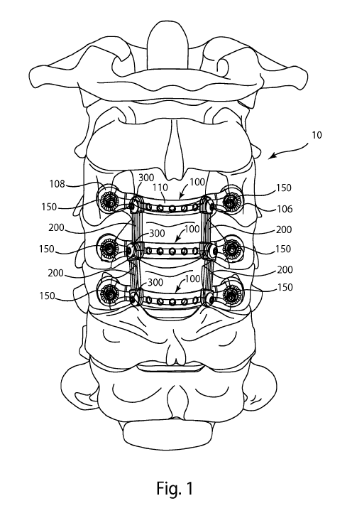
[0008] Figure 1 provides a posterior perspective view of a dynamic
stabilization system
according to one embodiment of the invention, secured to a portion of a spine;
[0009] Figure 2A provides a posterior perspective view of a bridge element of
the
dynamic stabilization system of Figure 1;
[0010] Figure 2B provides an anterior view of the bridge element of Figure 2A;
[0011] Figure 2C provides a caudal view of the bridge element of Figure 2A;
[0012] Figure 2D provides a medial perspective view of the bridge element of
Figure 2A;
[0013] Figure 3A provides a caudal view of a bridge element and two anchoring
members of the dynamic stabilization system of Figure 1;
3
CA 02726387 2010-11-29
WO 2009/155360 PCT/US2009/047684
[0014] Figure 3B provides an exploded perspective view of an anchoring member
of
Figure 3A;
[0015] Figure 4 provides an enlarged caudal cross-sectional view of a portion
of the
bridge element and one anchoring member of Figure 3A, anchored in a vertebra;
[0016] Figure 5A provides an enlarged perspective view of an elastically
deformable bias
element of Figure 1;
[0017] Figure 5B provides an enlarged perspective view of an alternate
embodiment of an
elastically deformable bias element;
[0018] Figure 5C provides an enlarged perspective view of an alternate
embodiment of an
elastically deformable bias element;
[0019] Figure 5D provides an enlarged perspective view of an alternate
embodiment of
an elastically deformable bias element;
[0020] Figure 6 provides a partially exploded perspective view of a bridge
element, two
bias elements, two attachment mechanisms and two anchoring members of the
dynamic
stabilization system of Figure 1;
[0021] Figure 7 provides a posterior perspective view of an alternate
embodiment of a
dynamic stabilization system, comprising two elastically deformable bias
elements and two
rigid bias elements, anchored to a portion of a spine;
[0022] Figure 8 provides a posterior perspective view of an alternate
embodiment of a
stabilization system, comprising four bias elements, anchored to a portion of
a spine;
[0023] Figure 9 provides a posterior perspective view of an alternate
embodiment of a
dynamic stabilization system, comprising two bias elements attached to bridge
elements at
the vertebral midline, anchored to a portion of a spine;
[0024] Figure 10 provides a posterior perspective view of an alternate
embodiment of a
dynamic stabilization system, comprising two elastically deformable bias
elements attached
4
CA 02726387 2010-11-29
WO 2009/155360 PCT/US2009/047684
to cross each other at one vertebral level, and two rigid bias elements at a
second vertebral
level, anchored to a portion of a spine;
[0025] Figure 11 provides a posterior perspective view of an alternate
embodiment of a
dynamic stabilization system comprising a bias element extending across two
vertebral
levels, anchored to a portion of a spine;
[0026] Figure 12A provides a posterior perspective view of a bridge element of
the
dynamic stabilization system of Figure 11;
[0027] Figure 12B provides a caudal perspective view of the bridge element of
Figure
12A;
[0028] Figure 12C a perspective view of a clamp of the dynamic stabilization
system of
Figure 11;
[0029] Figure 12D provides a perspective view of the clamp of Figure 12C;
[0030] Figure 13 provides a perspective view of an alternate embodiment of a
dynamic
stabilization system comprising two elastically deformable bias elements
extending across
two vertebral levels, anchored to a portion of a spine, and a tensioning tool;
[0031] Figure 14 provides a posterior perspective view of an alternate
embodiment of a
dynamic stabilization system, anchored to a portion of a spine;
[0032] Figure 15A provides a posterior perspective view of a bridge element of
the
dynamic stabilization system of Figure 14;
[0033] Figure 15B provides a perspective view of a portion of the bridge
element of
Figure 15A;
[0034] Figure 15C a perspective view of a clamp of the dynamic stabilization
system of
Figure 14; and
[0035] Figure 15D provides a perspective view of the clamp of Figure 15C.
CA 02726387 2010-11-29
WO 2009/155360 PCT/US2009/047684
(THIS PAGE WAS FOUND NUMBERED, BUT BLANK, BY THE ROIUS)
6
CA 02726387 2010-11-29
WO 2009/155360 PCT/US2009/047684
DETAILED DESCRIPTION OF THE PREFERRED EMBODIMENTS
[0036] The present invention relates to systems and methods for providing
dynamic
stabilization between spinal segments. Those of skill in the art will
recognize that the
following description is merely illustrative of the principles of the
invention, which may be
applied in various ways to provide many different alternative embodiments.
This description
is made for the purpose of illustrating the general principles of this
invention and is not meant
to limit the inventive concepts in the appended claims.
[0037] Disclosed herein is a novel technology that allows reconstitution of
the posterior
tension band following decompression with laminectomy. The system allows semi-
constrained motion between the spinal segments, preserving the normal mobility
of the spine,
while providing a restoring force that prevents post-operative kyphosis as
well as allows
correction of pre-existing deformity in the sagittal and/or coronal planes.
Thus the system
provides motion restoration with the addition of balance control. In an
implantation
procedure, lateral mass screws may be placed with a modified Magerl technique
using
anatomic landmarks. Laminectomy may be performed following placement of the
screws and
the decompression is achieved. Alternately, screws may be placed first,
followed by
laminectomy. Finally, the novel posterior cervical dynamic stabilization
system is affixed to
the cervical spine. In the lumbar or thoracic spine, the novel posterior
dynamic stabilization
system could be affixed via pedicle screws. The following novel embodiments
could be
easily adapted for the lumbar and thoracic spines.
[0038] Referring to Figure 1, one embodiment of a posterior dynamic
stabilization system
is shown secured to a portion of a spine. In the embodiment depicted,
laminectomy has
been performed on the C3, C4 and C5 cervical vertebrae. The system 10
comprises at least
two bridge elements 100, each of which is sized and shaped to span medial-
laterally across
the resected vertebra between the lateral masses. Each bridge element 100
comprises a first
7
CA 02726387 2010-11-29
WO 2009/155360 PCT/US2009/047684
anchoring feature 106, a second anchoring feature 108, and a bridge body 110
extending
between and connecting the anchoring features. Each bridge element 100 may be
secured to
a vertebra by at least one anchoring member 150. Each anchoring member 150 may
comprise an anchor or screw sized and shaped to be received in an anchoring
feature 106 or
108, and may interface with the anchoring feature to secure the bridge element
100 to the
bone. At least one bias element 200 is attached at one end to one bridge
element 100, and at
another end to a second bridge element 100, via attachment mechanisms 300.
Each bias
element 200 may be elastically deformable to provide dynamic stabilization
between the
vertebrae involved. In alternative embodiments, one or more bias elements may
comprise a
more rigid material to provide a stiffer degree of stabilization. The system
10 depicted in
Figure 1 includes four elastically deformable bias elements, allowing semi-
constrained
motion between the spinal segments, preserving the normal mobility of the
spine. The
distribution of the bias elements may be symmetrical as seen in Figure 1,
while alternative
embodiments include asymmetrically arranged bias elements.
[0039] Referring to Figures 2A - 2D, views of bridge element 100 are seen from
several
perspectives. Bridge element 100 may be referred to as a laminar bridge, and
is essentially a
prosthetic lamina to replace the lamina that has been removed during the
laminectomy for
decompression. The laminar bridge preferably includes bone ingrowth contact
areas that
contact the bone and encourage long-term bony fixation, areas which are
ideally located on
the anterior faces near the bone anchor attachment location, in order to
contact the posterior
aspects of the lateral masses. The laminar bridge is shaped to be situated
well above the
thecal sac to prevent any contact with the dura. Bridge element 100 may
comprise titanium,
stainless steel, aluminum, cobalt chrome, Nitinol, PEEK (poly ether ether
ketone), UHMWPE
(ultra high molecular weight polyethylene), or other suitable sufficiently
rigid biocompatible
8
CA 02726387 2010-11-29
WO 2009/155360 PCT/US2009/047684
materials. In alternate embodiments, a bridge element may comprise an
elastically
deformable material.
[0040] The bridge elements may take many forms other than those depicted here
to
accomplish the same function. For example, a bridge element may comprise two
or more
parts instead of the monolithic version shown. The bridge may be tubular in
form or include
hollow portions to improve radiographic visualization if needed. In addition,
the size of each
bridge element can vary as needed. For example, in some cases, such as when a
greater
clearance of the dural sac is required on one side of the vertebra, a wider
and/or longer
anchoring feature may be required on such one side. Also, the length, width,
thickness and/or
height of the bridge body may vary as required by patient anatomy or as needed
for a desired
correction. A bridge element may be medial-laterally symmetrical as depicted
in Figures 2A-
2D, or asymmetrical as needed.
[0041] Each bridge element 100 comprises a first end 102 having an anchoring
feature
106, and a second end 104 having an anchoring feature 108. The bridge element
100 further
comprises a posterior side 112 and a generally opposite anterior side 114. A
plurality of
individual discretely located attachment features 118 are distributed along
the bridge body
110. The attachment features, which may be threaded to engage corresponding
threads on an
attachment mechanism, may be distributed evenly or unevenly along the bridge
body.
[0042] Referring to Figures 2A and 2B, anchoring feature 106 includes an
aperture 116
extending from the posterior side to the anterior side of the bridge element.
The aperture 116
depicted is substantially cylindrical; however in other embodiments the
aperture may be
tapered to accommodate polyaxial adjustability of an anchoring member received
in the
aperture. On the posterior side, a concave cutout 120 encircles the aperture
opening. The
cutout 120 allows for polyaxial adjustment of the anchoring member, and is
faceted to
interface with a correspondingly faceted surface of the anchoring member. In
addition to or in
9
CA 02726387 2010-11-29
WO 2009/155360 PCT/US2009/047684
place of faceting, the cutout may include surface features such as divots,
splines, knurling,
longitudinal grooves, circumferential grooves, facets, nubs, and combinations
thereof, and/or
include surface treatments, roughening or excoriation to promote gripping
contact between
the anchoring feature and the anchoring member, and to prevent unintended
backout of the
anchoring member.
[0043] The anterior surface of the anchoring feature 106 includes a bone
apposition
portion 122. The bone apposition portion 122 may be knurled as depicted in
Figures 2B and
2C, and/or may include features such as roughening, excoriation, porous
structures or
treatments such as porous titanium coating, plasma-sprayed titanium,
hydroxylapatite
coating, tricalcium phosphate coating, to promote gripping contact and to
promote bony
ingrowth for long-term fixation. As seen in Figures 2C and 2D, the anterior
surface of the
anchoring feature 106 may be angled relative to the posterior surface of the
bridge element, to
optimally correspond to the natural or resected bone surface to which it is
secured during
implantation. Anchoring feature 108, found at the second end 104 of the bridge
element 100,
includes aperture 124 and bone apposition portion 126, which correspond to
those of
anchoring feature 106.
[0044] As seen in Figures 2A-2D, bridge body 110 extends medial-laterally
between
anchoring feature 106 and anchoring feature 108. Bridge body 110 is curved or
arched to
avoid contact with the dura when implanted, and a posterior height h of the
curve or arch may
exceed the height of the removed natural lamina. The attachment features 118
depicted are
holes, which may include threads for engagement with threaded attachment
members. Other
embodiments may include attachment features which are at continuous non-
discrete locations
along the bridge body. Other embodiments may also include attachment features
configured
to engage various attachment mechanisms such as clamps, threaded fasteners,
locking nuts,
posts, holes, press-fits, quick-release and quick-attachment connections, 1/4-
turn connections,
CA 02726387 2010-11-29
WO 2009/155360 PCT/US2009/047684
t-slots, dovetail joints, living hinges, and flanges, among others. All of the
attachment
features 118 may be medially offset from the anchoring features 106, 108 when
the bridge
element 100 is properly secured to a vertebra in the manner set forth herein,
that is, in a
medial-lateral orientation so as to span the vertebra.
[0045] Referring to Figures 3A and 3B, a single bridge element 100 may be
secured by
two anchoring members 150. In the embodiment depicted, anchoring member 150
comprises
bone anchor 152 and nut 154, which may be a locking nut. Bone anchor 152
comprises distal
threaded portion 156, proximal threaded shank 158, and drive feature 160. In
the depicted
embodiment, drive feature 160 is an external hex drive and is positioned
between the distal
and proximal threaded portions; however in other embodiments the drive feature
may be
internal and/or comprise a different shape or location. For example, an
alternate anchoring
member may comprise a screw with a proximally located internal drive feature
having a
rectangular, triangular or pentagonal shape. Other suitable screw-type bone
anchors may
include lateral mass screws, monoaxial bone screws, polyaxial bone screws,
screws with
spherical heads, pedicle screws, screws with trilobular or lobular heads,
tulip heads, proximal
shanks, nuts, slots, serrations, or grooves, among others. Yet other anchoring
members may
be substituted for bone screws, such as staples, wires, cable, clamps, or
hooks, among others.
Anchoring members may include structures to assist in long-term fixation,
including but not
limited to porous titanium coating, plasma-sprayed titanium, hydroxylapatite
coating,
tricalcium phosphate coating, porous structures and/or rough surface
treatments.
[0046] Nut 154 comprises an internal lumen 162 shaped to engage with the bone
anchor
152. In the embodiment depicted, internal lumen 162 is threaded such that it
may threadedly
engage the proximal threaded portion 158 of the bone anchor 152. Nut 154
further comprises
a drive portion 164 and an interface portion 166. The interface portion 166 is
convex and
comprises surface facets which correspond to the faceting of concave cutout
120 on the
11
CA 02726387 2010-11-29
WO 2009/155360 PCT/US2009/047684
bridge element. Other embodiments of the interface portion 166 may comprise
facets, and/or
other surface features such as divots, splines, knurling, longitudinal
grooves, circumferential
grooves, facets, nubs, and combinations thereof, and/or include surface
treatments,
roughening or excoriation.
[0047] Referring to Figure 4, a cross-sectional view of an anchoring member
150 in
engagement with a bridge member 100 is shown. Distal threaded portion 156 of
bone anchor
152 is engaged in a bone, and anchoring feature 106 is placed over the bone
screw such that
aperture 116 surrounds drive feature 160 and bone apposition portion 122
contacts the
surface of the bone. Nut 154 is threaded onto the proximal threaded shank 158
to secure
bridge member 100 to the bone, and convex interface portion 166 engages with
concave
cutout 120. The inner diameter of concave cutout 120 is greater than the outer
diameter of
convex interface portion 166, to allow for polyaxial positioning of anchoring
member 150.
As set forth previously, aperture 116 may also be tapered at its distal, or
bone-engaging, end
to also allow polyaxial placement of anchoring member 150.
[0048] As seen in Figure 1, multiple bias elements 200 are each coupled at a
cephalad
end to a first bridge element 100, and coupled at a caudal end to a second
bridge element 100.
In the embodiment shown, bias element 200 comprises a compliant, elastically
deformable
material which allows constrained motion between the first and second bridge
elements. Such
compliant, elastically deformable materials may include elastomers, silicones,
urethanes, bio-
absorbable materials, woven textile structures, knit textile structures,
braided textile
structures, molded thermoplastic polymers, ethylene-vinyl acetate, PEEK, or
UHMWPE; and
materials such as Nitinol, titanium, and stainless steel formed into
elastically deformable
structures such as springs.
[0049] The bias element is intended to replicate or partially simulate the
natural posterior
tension band in order to place physiologic constraints to motion and balance
once these
12
CA 02726387 2010-11-29
WO 2009/155360 PCT/US2009/047684
natural structures have been compromised after surgery. The preferred
embodiment includes
a compliant material which is suited for tension / extension, such as a
silicone or elastomer.
The bias element is preferably configured with two attachment ends to be
secured to the
laminar bridges, as well as a central portion which may be bowed posteriorly
in order to
encourage buckling in posterior direction during patient extension. During
patient flexion,
the bias element incurs tensile forces and the bias element resists those
partially incurring
deflection and allowing the flexion to occur. The bias element may allow all
anatomic range
of motions seen in the spine including flexion, extension, lateral bending and
rotation. All
coupled motions may be possible. The bias element may have a restoring force,
preventing
the development of post-laminectomy deformity. The geometry of the bias
element may be
configured to provide a correcting force in all planes for correction of
sagittal and coronal
deformities.
[0050] Referring to Figures 5A-5D, different configurations of elastically
deformable
bias elements are shown. Bias element 200 comprises a first fixation portion
202, a second
fixation 204 and a bias body 206 extending between the first and second
fixation portions. In
the embodiment shown, the first and second fixation portions 202, 204 are each
formed from
a rigid material which is substantially more rigid and less compliant than the
elastically
deformable material. Such rigid materials may include titanium, stainless
steel, aluminum,
cobalt chromium, Nitinol, PEEK, and UHMWPE, among others. Each fixation
portion 202,
204 comprises a joining feature 208, which in the embodiment shown, is a hole.
The joining
feature 208 is configured to cooperate with an attachment mechanism to join or
attach the
bias element to a bridge element. The bias body 206 of bias element 200
comprises five
separate strands of an elastically deformable material. Other embodiments of
the bias element
may include more or fewer strands, and/or strands which are woven, braided,
knit, or
otherwise intertwined.
13
CA 02726387 2010-11-29
WO 2009/155360 PCT/US2009/047684
[0051] Referring to Figure 5B, bias element 210 comprises a bias body 212
having
accordion-type folds or pleats. Figure 5C illustrates a bias element 220 with
a substantially
flat bias body 222, and Figure 5D illustrates a bias element 230 having a bias
body 232 with a
flexure 234. It is appreciated that each material used, and/or configurations
of the bias body,
may be mixed and matched to provide bias elements with varying degrees of
elasticity as
necessary for the amount of motion and/or correction desired. In addition to
the bias elements
depicted, other bias elements within in the scope of the invention may have
different cross-
sectional geometries as well, such as circular, rectangular, ovoid, annular,
or any freeform
shape, as well as being solid, hollow, or porous. Also, bias elements may vary
in length
and/or width to provide varying degrees of elasticity or compliance.
[0052] An alternative embodiment of the invention may include at least one
bias element
which is formed entirely of rigid materials, in order to provide additional
motion or balance
control constraints on the functional spinal unit, or motion segment,
involved. Rigid materials
suitable for such a more rigid, less compliant bias element include titanium,
stainless steel,
aluminum, cobalt chromium, Nitinol, PEEK, and UHMWPE, among others. A rigid
bias
member may be monolithically formed as one piece, or may include a body
portion and
fixation portions which are rigidly joined together. A system comprising rigid
bias elements
coupled between bridge elements may provide a rigid stabilizing force between
the bridge
elements. It is appreciated that compliant and rigid bias elements may be
mixed and matched
to achieve the customized needs of the patient in a multi-level procedure. The
bias element(s)
may be configured to specifically introduce sagittal (lordosis or kyphosis) or
coronal balance.
Alternatively, or in addition, the bias element(s) may introduce anterior or
posterior
translation.
[0053] Referring to Figure 6, a partially exploded view shows a bridge element
200 with
a bias member 200 attached to the bridge, and an unattached bias member 200
and
14
CA 02726387 2010-11-29
WO 2009/155360 PCT/US2009/047684
attachment mechanism 300. In the embodiment depicted, attachment mechanism 300
comprises a screw 310. Screw 310 includes a head portion 312 and a threaded
shaft 314. The
head portion 312 includes a drive feature 316 which in the example shown is
internal; other
embodiment may include an external drive feature. To attach the bias member
200 to the
bridge element 100, the first fixation portion 202 may be placed adjacent the
desired
attachment feature 118 such that their respective holes are aligned, then
shaft 314 inserted
through joining feature 208 and engaged in attachment feature 118.
Alternately, the shaft 314
may be inserted through joining feature 208, then screw 310 and bias element
200 are moved
together toward the bridge element and the screw 310 engaged with the
attachment feature
118 to attach the bias element to the bridge element. The joining feature 208
of the bias
element 200 may not be threaded, to allow angular adjustment of the bias
element relative to
the bridge elements before the position of the bias element is fixed by
engaging the
attachment mechanism 300 with the attachment feature 118.
[0054] Attachment mechanism 300 may be a self-locking screw, or may comprise a
locking washer, or backup nut to ensure locking engagement with the bias
member and the
bridge element, and to prevent unintended backout or removal of the attachment
mechanism.
It is appreciated that attachment mechanism 300 is removable to provide for
revision or
adjustment of the bias element relative to the bridge elements. It is also
appreciated that other
attachment mechanisms exist to secure the bias element to the laminar bridge,
including but
not limited to clamps, clips, threaded fasteners, posts, holes, press-fits,
quick-release and
quick-attachment connections, 1/4-turn connections, t-slots, dovetail joints,
living hinges, and
flanged connections.
[0055] Referring again to Figures 1, 3A and 3B, and 6, system 10 may be
implanted as
follows. The cervical vertebrae are exposed, and bone anchors 152 are placed
with a modified
Magerl technique using anatomic landmarks. Laminectomy is then performed
following
CA 02726387 2010-11-29
WO 2009/155360 PCT/US2009/047684
placement of the anchors, and decompression is achieved. Alternatively,
laminectomy may
first be performed followed by placement of the anchors. Bridge elements 100
are placed
over the bone anchors and secured to the resected vertebrae by nuts 154. Two
bridge
elements 100 may be secured to adjacent vertebrae for single level
stabilization, or three or
more bridge elements may be used to provide stabilization across multiple
levels. Bias
elements 200 are attached to the bridge elements via attachment mechanisms
150. Each bias
element may be attached to the bridge elements such that it extends
essentially perpendicular
to the bridge elements, as in Figure 1, or may be attached in a non-
perpendicular position. As
bias elements are attached, tension may be applied manually or with a
tensioning tool to
achieve a desired tension between the bridge elements. Of course, the
implantation methods
set forth herein may be applied to any of the posterior dynamic stabilization
systems or
variations disclosed.
[0056] Figures 7 -14 show alternative embodiments of posterior dynamic
stabilization
systems. In Figure 7, system 12 comprises three bridge elements 100 secured to
three
respective vertebrae. Elastically deformable bias elements 200 are secured
bilaterally
between the first and second bridge elements, to provide dynamic stabilization
at that
vertebral level. Rigid bias elements 400 are secured bilaterally to the second
and third bridge
elements, to provide rigid stabilization at that vertebral level. Another
alternative
embodiment could include elastically deformable bias elements secured to
bridges at one
vertebral level, and different elastically deformable bias elements with a
lower or higher
degree of elasticity, at a second vertebral level.
[0057] Referring to Figure 8, system 14 comprises three bridge elements 100
secured to
three respective vertebrae. Rigid bias elements 400 are secured bilaterally to
the first and
second bridge elements and to the second and third bridge elements, to provide
rigid
stabilization at both vertebral levels. In an alternative embodiment of system
14, the bridge
16
CA 02726387 2010-11-29
WO 2009/155360 PCT/US2009/047684
elements may comprise elastically deformable material while the bias elements
comprise
rigid material, to provide dynamic stabilization at both vertebral levels.
[0058] Referring to Figure 9, system 16 comprises three bridge elements 100
secured to
three respective vertebrae. An elastically deformable bias element 200 is
attached to the first
and second bridge elements, aligned with the midline or sagittal plane of the
vertebrae and
the bridge elements. A second elastically deformable bias element 200 is
attached to the
second and third bridge elements, and is also aligned with the midline or
sagittal plane of the
vertebrae and the bridge elements. It is appreciated that the second
deformable bias element
may have the same, or different, elasticity as the first bias element. Another
alternative
embodiment could include rigid bias elements 400 aligned along the midline or
sagittal plane
at one or both vertebral levels.
[0059] Referring to Figure 10, system 18 comprises three bridge elements 100
secured to
three respective vertebrae. A cephalad end of an elastically deformable bias
element 200 is
attached to the first bridge element, and a caudal end is attached to the
second bridge element at a
location medial-laterally offset from the first location. A second elastically
deformable bias
element 200 is attached in an opposite manner, so that the second bias element
crosses over
the first bias element. Such a configuration may aid in maintaining patient
balance and/or
correcting deformities in the sagittal and/or coronal planes. Two rigid bias
elements extend
between the second and third bridge elements to provide rigid stabilization at
that level.
[0060] Figures 11-14 depict posterior dynamic stabilization systems which each
include a
continuous length of elastically deformable material which is attached across
two vertebral
levels. Referring to Figure 11, system 20 comprises three bridge elements 130,
each of which
is oriented medial-laterally across a vertebra and secured to the vertebra via
two anchoring
members. A bias element 240 extends across all three bridge elements at a
midline or sagittal
position, and is coupled to each bridge element by an attachment mechanism
320.
17
CA 02726387 2010-11-29
WO 2009/155360 PCT/US2009/047684
Attachment mechanism 320 comprises a clamp 322 and a screw 324. The screw
engages the
clamp and the bridge element to both attach the clamp to the bridge element
and attach the
bias element to the clamp at a desired tension.
[0061] Bridge element 130 is shown in Figures 12A and 12B. Bridge 130
comprises a
first end having an anchoring feature 136, and a second end having an
anchoring feature 138.
A plurality of individual discretely located attachment features 148 are
distributed along a
bridge body 140. The attachment features, which may be threaded to engage
corresponding
threads on an attachment mechanism, may be distributed evenly or unevenly
along the bridge
body. In comparison with bridge element 100 as seen in Figure 2C, it can be
seen that the
bridge body 140 of bridge element 130 is flatter than bridge body 110 of
bridge element 100.
This flatter configuration helps to compensate for the anterior-posterior
dimension of the
clamp in order to provide a suitably low profile implant.
[0062] Figure 12C depicts a medial perspective view of clamp 322, and Figure
12D
depicts a caudal view of the clamp. The clamp 322 comprises an open loop
portion 325 sized
to receive a portion of bias material. A first tab 326 and a second tab 328
are continuations of
the loop portion 325. Tab 326 has an opening 330, and tab 328 has an opening
332, and the
tabs are positioned relative to one another such that the openings are
concentrically aligned.
Two stops 334, 336 extend from tab 328. When the clamp is positioned on a
bridge element
body 140 as in Figure 11, the stops 334, 336 project on either side of the
bridge body and
may prevent rotation of the clamp relative to the bridge body. Openings 330,
332 are sized
and shaped to receive a shaft of screw 324. As seen in Figure 11, clamp 322 is
positionable
on a bridge element at an attachment feature 148, with stops 334, 336
positioned on either
cephalad/caudal side of the bridge element. Bias element 240 is insertable
through the loop
portion 325. Screw 324 is insertable through clamp openings 330, 332 and into
the
attachment feature 148. When screw 324 is tightened, loop portion 325 closes
around bias
18
CA 02726387 2010-11-29
WO 2009/155360 PCT/US2009/047684
element 240, and clamp 322 is rigidly attached to the bridge element, unable
to rotate or
translate. It is also appreciated that other attachment mechanisms exist to
secure the bias
element to the bridge, including but not limited to clamps, clips, threaded
fasteners, posts,
holes, press-fits, quick-release and quick-attachment connections, 1/-turn
connections, t-slots,
dovetail joints, living hinges, and flanged connections.
[0063] Bias element 240 may comprise a single piece or multiple pieces of an
elastically
deformable material. The material composition, length, width, and/or
elasticity of bias
element 240 may vary as needed to attain the desired tension for balance
control, deformity
correction or other desired outcome.
[0064] Referring to Figure 13, posterior dynamic stabilization system 22
comprises three
bridge elements 131, 132, and 133, bias elements 240 and 242, assembled with a
plurality of
anchoring members and attachment mechanisms. Attachment mechanisms 341, 342,
343,
344, 345 and 346 may each comprise an attachment mechanism 320. Bias element
240 has
been tensioned and attached to the three bridge elements by attachment
mechanisms 341,
342, 343 to provide tension at two vertebral levels. Bias element 242
comprises a length of
elastically deformable material. During an implantation process, bias element
242 may be
inserted through the loop portions of attachment mechanisms 344, 345, 346. The
attachment
mechanism 344 on bridge element 131 may be tightened to firmly hold the bias
element 242.
A tensioning tool 450 may be coupled to a portion of the bias element, and
actuated to
provide tension to the bias element. The tensioning tool 450 comprises a
spring 452, the tool
configured such that deflection of the spring provides tension to the bias
element. The spring
deflection may be viewed through a window or slot in the tool and a
measurement scale may
be present on the tool to indicate the magnitude of tension on the bias
element. When a
desired tension is attained, the attachment mechanism 345 on bridge element
132 may be
tightened to lock down the bias element 242 at the desired tension. Finally,
the tension on
19
CA 02726387 2010-11-29
WO 2009/155360 PCT/US2009/047684
bias element 242 may be adjusted between bridge element 132 and 133 by
actuation of the
tensioning tool, and attachment mechanism 346 tightened to lock down the bias
element 242
at the desired tension. Bias element 242 may then be severed between
attachment mechanism
346 and the tensioning tool. It is appreciated that bias element may be
attached in the same
manner as bias element 242, and that the bias elements 240, 242 can be
inserted, tensioned
and locked down in a cephalad-to-caudal order, or vice versa. It is also
appreciated that a
third bias element may be added to the system to provide additional dynamic
support if
desired.
[0065] Another alternative embodiment of a posterior dynamic stabilization
system is
shown in Figure 14. System 24 comprises three bridge elements 180, each
secured in a
medial-lateral orientation to a vertebra by anchoring members 150. A single
bias element 250
is attached to first and second bridge elements 180 in a midline position. Two
additional bias
elements 250 are attached to the second and third bridge elements in a
bilateral arrangement.
Attachment mechanisms 350, which comprise clamp 352 and screw 354, attach the
bias
elements 250 to the bridge elements 180. Each bias element 250 comprises a
first fixation
portion 252, a second fixation portion 254, and a bias body 256, and each
fixation portion
comprises a joining feature 258.
[0066] Figures 15A-15D show the details of bridge element 180 and clamp 352.
Bridge
element 180 comprises a first end 182 having an anchoring feature 184, and a
second end 186
having an anchoring feature 188. Bridge body 190 has a circular cross-section,
and an outer
connection surface 192. In the embodiment depicted, the connection surface 192
is ridged in
order to promote a non-slipping grip connection between the bridge body and
the attachment
mechanism(s) 340. In alternative embodiments, connection surface 192 may
comprise other
gripping features such as knurling, longitudinal grooves, facets, nubs, and
combinations
thereof, and/or include surface treatments, roughening or excoriation. The
attachment
CA 02726387 2010-11-29
WO 2009/155360 PCT/US2009/047684
mechanisms 350 can be attached to the bridge element 180 at any location along
the bridge
body 190, thus providing a plurality of continuous non-discrete attachment
locations. This
configuration allows the practitioner to select the precise attachment
location needed to
produce the desired result, whether it is balance control, deformity
correction or a
combination.
[0067] As seen in Figures 15C and 15D, clamp 352 comprises an open loop
portion 356
sized to surround a portion of a bridge body 190. A first tab 358 and a second
tab 360 are
continuations of the loop portion 356. Tab 358 has an opening 362, and tab 360
has an
opening 364, and the tabs are positioned relative to one another such that the
openings are
axially aligned. Openings 362, 364 are sized and shaped to receive a shaft of
screw 354. As
seen in Figure 14, clamp 352 is positionable on a bridge body 180 at any non-
discrete
location along the body. One joining feature 258 of a bias element 250 may be
placed
adjacent the openings 362, 364 of the clamp 352. Screw 354 is insertable
through the joining
feature 258 and the clamp openings 362, 364. When screw 354 is tightened, loop
portion 356
closes around the bridge body 190, and clamp 352 is rigidly attached to the
bridge element.
Prior to tightening, clamp 352 may be rotated about the bridge body 190 to a
desired position.
This rotation allows for tension adjustment of the bias element 250 between
the two bridge
elements 180. Of course, during the implantation process, the positions of the
attachment
mechanisms along the lengths of bridge bodies may be adjusted, as can the
rotational position
of the attachment mechanism, by loosening the screw 354, making the desired
adjustment(s),
and re-tightening the screw. The second joining feature of bias element 250 is
attached to a
second bridge 180 in a similar fashion. It is also appreciated that other
attachment
mechanisms exist to secure the bias element to the bridge, including but not
limited to
clamps, clips, threaded fasteners, locking nuts, posts, holes, press-fits,
quick-release and
21
CA 02726387 2010-11-29
WO 2009/155360 PCT/US2009/047684
quick-attachment connections, 1/4-turn connections, t-slots, dovetail joints,
living hinges, and
flanged connections.
[0068] The present invention may be embodied in other specific forms without
departing
from its spirit or essential characteristics. For example, above are described
various
alternative examples of systems for providing posterior dynamic stabilization.
It is
appreciated that various features of the above-described examples can be mixed
and matched
to form a variety of other alternatives. For example, elastically deformable
and rigid bias
elements may be used in combination or separately. The bias elements may be
placed parallel
to one another and perpendicular to the bridging elements, or non-parallel
and/or non-
perpendicular. It is also appreciated that this system should not be limited
to the cervical
spine, and may be used on any portion of the spine. As such, the described
embodiments are
to be considered in all respects only as illustrative and not restrictive. The
scope of the
invention is, therefore, indicated by the appended claims rather than by the
foregoing
description. All changes which come within the meaning and range of
equivalency of the
claims are to be embraced within their scope.
22