Note: Descriptions are shown in the official language in which they were submitted.
CA 02729280 2011-01-25
DIELECTRIC JAW INSERT FOR ELECTROSURGICAL END EFFECTOR
BACKGROUND
Technical Field
[0001] The present disclosure relates to varying sealing characteristics of a
bipolar
electrosurgical instrument with a monolithic jaw member. More particularly,
the present
disclosure relates to varying sealing characteristics by using a dielectric
insert within a
monolithic jaw member.
Description of Related Art
[0002] Open or endoscopic electrosurgical forceps utilize both mechanical
clamping
action and electrical energy to effect hemostasis. The electrode of each
opposing jaw
member is charged to a different electric potential such that when the jaw
members grasp
tissue, electrical energy can be selectively transferred through the tissue.
Many times
monolithic jaw members having a one-piece metallic configuration are utilized
during
such procedures. The monolithic jaw configuration allows for an efficient and
easier
manufacturing process, since fewer parts are needed to assemble a single jaw
member.
[0003] Additionally, certain types of open and endoscopic electrosurgical
forceps, as
mentioned above, utilize a movable knife or cutting element that is movable
via a cutting
channel. Cutting channel is defined by a jaw member and is often characterized
as a
narrow cavity within one or both jaw members. Throughout a typical surgical
procedure,
various conductive fluids, for example, blood or saline may fill the cutting
channel of a
-1-
CA 02729280 2011-01-25
jaw member. Since the entire depth of the cutting channel is part of the
electrical circuit
in this type of jaw, material in the blade slot may become subject to the
electrosurgical
effect and may affect a cycle and/or a quality of a tissue seal. When this or
similar
situations occur, unnecessary complications arise for the user during a
surgical procedure.
SUMMARY
[0004] The present disclosure relates to an end effector assembly for use with
an
electrosurgical instrument. The end effector assembly includes a pair of
opposing first
and second jaw members and a jaw insert. Each of the opposing jaw members has
a
tissue contacting surface and one or more of the jaw members are monolithic.
Additionally, at least one of the jaw members is moveable relative to the
other from a
first, open position to a second, closed position for grasping tissue. The
monolithic jaw
member also has a cavity defined therein. The jaw insert is selectively
positionable
within the cavity of the monolithic jaw member. The jaw insert includes a
tissue
contacting surface and a portion of the jaw insert includes a dielectric
material configured
to reduce the thermal mass of the monolithic jaw member.
[0005] In embodiments, the jaw insert may define a cutting channel therealong
configured to receive a cutting element therealong. The jaw insert may include
a portion
of conductive material that is configured to conduct electrosurgical energy
received from
the electrosurgical energy source. The jaw insert may also be overmolded to
the
monolithic jaw member. In embodiments, the jaw insert may include one or more
mechanical interfaces that cooperate with corresponding mechanical interfaces
to
-2-
CA 02729280 2011-01-25
selectively position the jaw insert within the cavity. The mechanical
interfaces may
include one or more biasing members.
[0006] In embodiments, the tissue contacting surface of the at least one
monolithic
jaw member and the tissue contacting surface of the jaw insert may be offset
relative to
one another. Additionally, the tissue contacting surface of the jaw insert may
be raised
relative to the tissue contacting surface of the monolithic jaw member to form
a gap
between the monolithic jaw member and the opposing jaw member in the range of
about
0.00 1 inches to about 0.006 inches. The jaw insert may be removable from the
cavity.
[0007] The present disclosure also relates to a method of manufacturing an end
effector assembly for use with an electrosurgical instrument. The method
includes a step
of fabricating opposing jaw members, at least one jaw member being monolithic
and
having a cavity defined therein. In another step, a jaw insert is fabricated
having a
portion including a dielectric material configured to reduce the thermal mass
of the
monolithic jaw member. In another step, the jaw insert is positioned within
the cavity of
the monolithic jaw member.
[0008] In other embodiments, the method includes the step of fabricating the
jaw
insert to define a cutting channel configured to receive a cutting element
therealong. In
another step, the jaw insert may be fabricated to include a portion of
conductive material
configured to conduct electrosurgical energy received from the electrosurgical
energy
source. In another step, the jaw insert is overmolded and positioned within
the cavity of
the monolithic jaw member. In another step, the jaw insert may be fabricated
to include
- J -
CA 02729280 2011-01-25
one or more mechanical interfaces that cooperate with a corresponding
mechanical
interface disposed within the cavity. In another step, a tissue contacting
surface of the
monolithic jaw member may be offset from a tissue contacting surface of the
jaw insert.
BRIEF DESCRIPTION OF THE DRAWINGS
[0009] Various embodiment of the subject instrument are described herein with
reference to the drawings wherein:
[0010] Fig. 1A and 113 are perspective views of an endoscopic forceps and an
open
forceps for electrosurgical treatment having an end effector assembly in
accordance
with an embodiment of the present disclosure;
[0011] Fig. 2A is a cross-sectional view of an end effector assembly having a
jaw
insert in accordance with an embodiment of the present disclosure;
[0012] Fig. 2B is an exploded view of the end effector assembly of Fig. 2A;
[0013] Fig. 2C is a top view of an end effector assembly of Fig. 2A having a
cutting
channel;
[0014] Fig. 2D is a top view of an end effector assembly of Fig. 2A having an
offset cutting channel;
[0015] Fig. 2E is a top view of an end effector assembly similar to the end
effector
of Fig. 2A having an angled cutting channel;
-4-
CA 02729280 2011-01-25
[0016] Fig. 3A is a cross-sectional view of another embodiment of an end
effector
assembly having a jaw insert in accordance with an embodiment of the present
disclosure;
[0017] Fig. 3B is an exploded view of the end effector assembly of Fig. 3A;
[0018] Fig. 3C is a top view of an end effector assembly of Fig. 3A having a
cutting
channel;
[0019] Fig. 4A is a cross-sectional view of yet another embodiment of an end
effector
assembly having a jaw insert in accordance with an embodiment of the present
disclosure;
[0020] Fig. 4B is an exploded view of yet another embodiment of an end
effector
assembly including a jaw insert having a cutting channel in accordance with an
embodiment of the present disclosure;
[0021] Fig. 4C is a top view of the end effector assembly of Fig. 4A; and
[0022] Figs. 5A-5C are cross-sectional views of an end effector assembly
including a
jaw insert having various configurations.
-5-
CA 02729280 2011-01-25
DETAILED DESCRIPTION
[00231 Embodiments of the presently-disclosed electrosurgical instrument are
described in detail with reference to the drawings wherein like reference
numerals
identify similar or identical elements. As used herein, the term "distal"
refers to that
portion which is further from a user while the term "proximal" refers to that
portion
which is closer to a user. As used herein, the term "monolithic jaw member"
refers to a
jaw member of an end effector for a bipolar electrosurgical device having a
one-piece
configuration. More specifically, a major portion of the jaw member, including
the
electrode surface (e.g., a sealing surface) is machined from a one-piece
conductive
material, for example, but not limited to stainless steel. When the monolithic
jaw
member is configured to have a cutting channel, the cutting channel is
machined (e.g.,
bored) into and along the length of the jaw member such that a cutting element
may
travel therethrough.
100241 The present disclosure relates to modifying sealing characteristics of
monolithic jaw members by embedding a dielectric jaw insert within the
monolithic jaw
members of the end effector assembly. The dielectric jaw insert modifies the
seal area
and thermal mass of the end effector by allowing the combination of materials
in the
structure to be altered. Additionally, the dielectric jaw insert can contain
features such as
a cutting channel to allow a cutting element to pass therethrough. In this
manner, the
cutting channel is electrically insulated from the monolithic jaw member such
that fluids
that are trapped in the cutting channel are not subject to the electrosurgical
effect. The
dielectric jaw inserts may be a discrete part separate from the end effector
assembly or, in
-6-
CA 02729280 2011-01-25
the alternative, may be molded into the monolithic jaw members during a
manufacturing
step. All of these novel features will be described in greater detail further
below.
[00251 Referring now to the figures, Fig. IA depicts a forceps 10 used in
correlation
with endoscopic surgical procedures and Fig. 1B depicts an open forceps 50
used in
correlation with more traditional open surgical procedures. For the purposes
herein,
either an endoscopic instrument or an open instrument may be utilized with the
cutting
assembly described herein. It should be noted that different electrical and
mechanical
connections and considerations apply to each particular type of instrument.
However, the
novel aspects, with respect to the cutting assembly and its operating
characteristics,
remain generally consistent with respect to both the endoscopic or open
designs.
[00261 Turning now to Fig. IA, a tissue treatment system 2 according to the
present
disclosure is shown including a forceps 10 coupled to an electrosurgical
energy source
22. Forceps 10 is particularly adapted to seal tissue using radiofrequency
(RF) however,
other types of suitable energy, for example, but not limited to light energy
and microwave
energy may be utilized to electrosurgically treat tissue. Energy source 22 is
configured to
output various types of energy such as RF energy (e.g., from about 300 MHz to
about
5000 MHz). In addition, where laser energy is used, the energy source 22 may
be a light
source. If ultrasonic energy is desired, the energy source 22 may be adapted
to provide
an electrical excitation signal to one or more ultrasonic transducers within
forceps 10.
Forceps 10 is coupled to the energy source 22 via a cable 20 adapted to
transmit the
appropriate energy and control signals therebetween. Various embodiments of
forceps 10
utilizing the aforementioned types of energy are discussed in more detail
below.
-7-
CA 02729280 2011-01-25
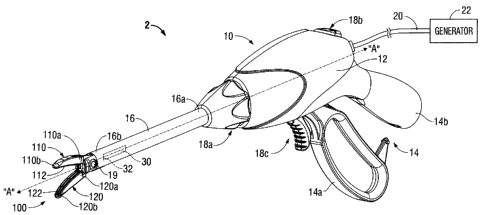
[0027] Forceps 10 is configured to support an end effector assembly 100.
Forceps 10
typically includes various conventional features (e.g., a housing 12, a handle
assembly
14, a rotating assembly 18a and a trigger assembly 18b) which enable forceps
10 and end
effector assembly 100 to mutually cooperate to grasp, seal and/or divide
tissue grasped
therebetween. Forceps 10 generally includes housing 12 and handle assembly 14
that
includes moveable handle 14a and a fixed handle 14b which is integral with
housing 12.
Handle 14a is moveable relative to handle 14b to actuate end effector assembly
100 to
grasp tissue. Forceps 10 also includes shaft 16 that has distal end 16b that
mechanically
engages end effector assembly 100 and proximal end 16a that mechanically
engages
housing 12 proximate rotating assembly 18a disposed at the distal end of
housing 12.
Rotating assembly 18a is mechanically associated with shaft 16. Movement of
rotating
assembly 18a imparts similar rotational movement to shaft 16 which, in turn,
rotates end
effector assembly 100.
[0028] End effector assembly 100 includes two jaw members 110 and 120 having
proximal ends 110a, 120a and distal ends 110b, 120b, respectively. One or both
jaw
members 110 and 120 are pivotable about a pivot pin 19 and are movable from a
first
position wherein jaw members 110 and 120 are spaced relative to another, to a
second
position wherein jaw members 110 and 120 are closed and cooperate to grasp
tissue
therebetween. That is, jaw members 110 may have a unilateral configuration
(e.g., only
one jaw member is movable) and/or a bilateral configuration (e.g., both jaw
members are
movable). As discussed in more detail below, the end effector assembly 100 may
include
a removable dielectric insert.
-8-
CA 02729280 2011-01-25
[00291 A switch assembly 18b is configured to selectively provide electrical
energy
to the end effector assembly 100. More particularly, switch assembly I8b is
configured
to selectively supply electrical energy to tissue contacting surfaces 112 and
122 of jaw
member 110 and 120, respectively. Cable 20 connects the forceps 10 to a source
of
electrosurgical energy 22, for example, but not limited to, an electrosurgical
generator.
Cable 20 is internally divided (not shown) within the handle assembly 14 and
the shaft 16
to transport electrosurgical energy through various conductive paths and
ultimately to end
effector assembly 100. In this manner, the end effector assembly 100 may
electrosurgically treat tissue.
[00301 In addition to switch assembly 18b, forceps 10 also includes a trigger
assembly 18c that is operably coupled to and advances a cutting element 30
(see
phantom) disposed within the end effector assembly 100. Once a tissue seal is
formed,
the user activates the trigger assembly 18c to separate the tissue along the
tissue seal.
Cutting element 30 may include a sharpened edge 32 for severing the tissue
held between
the jaw members 110 and 120 at the tissue sealing site.
[0031] Referring now to Fig. 1B, an open forceps 50 is depicted and includes
end
effector assembly 100 (similar to forceps 10) that is attached to a pair of
elongated shaft
portions 52a and 52b. Elongated shaft portions 52a and 52b have proximal ends
54a and
54b and distal ends 56a and 56b, respectively. The end effector assembly 100
includes
jaw members 110 and 120 that attach to distal ends 56a and 56b of shafts 52a
and 52b,
respectively. The jaw members 110 and 120 are connected about pivot pin 55
that allows
the jaw members 110 and 120 to pivot relative to one another from the first to
second
-9-
CA 02729280 2011-01-25
positions for treating tissue (as described above). The tissue contacting
surfaces (e.g.,
seal plates) 112 and 122 are connected to opposing jaw members 110 and 120 and
include electrical connections through or around the pivot pin 55.
[0032] Each shaft 52a and 52b includes a handle 57a and 57b disposed at the
proximal end 54a and 54b thereof. Handles 57a and 57b facilitate movement of
the
shafts 52a and 52b relative to one another which, in turn, pivot the jaw
members 110 and
120 from the open position wherein the jaw members 110 and 120 are disposed in
spaced
relation relative to one another to the clamping or closed position wherein
the jaw
members 110 and 120 cooperate to grasp tissue therebetween.
[0033] In an example embodiment, as depicted in Fig. 1B, a ratchet 58 (e.g.,
hemostat
clamp) may be included for selectively locking the jaw members 110 and 120
relative to
one another at various positions during pivoting. The ratchet 58 is configured
to hold a
specific, i.e., constant, strain energy in the shaft members 52a and 52b
which, in turn,
transmits a specific closing force to the jaw members 110 and 120. It is
envisioned that
the ratchet 58 may include graduations or other visual markings that enable
the user to
easily and quickly ascertain and control the amount of closure force desired
between the
jaw members 110 and 120.
[0034] With continued reference to Fig. 1 B, forceps 50 is depicted having a
cable 59
that connects the forceps 50 to a source of electrosurgical energy, e.g.,
generator 22. In a
similar fashion to forceps 10, cable 59 of forceps 50 is internally divided
within the shaft
-10-
CA 02729280 2011-01-25
52b to transmit electrosurgical energy through various electrical conductive
paths to the
components of the end effector assembly 100.
[0035] In embodiments, a switch assembly 53a may be configured to selectively
provide electrical energy to the end effector assembly 100. More particularly,
switch
assembly 53a is configured to selectively supply electrical energy to tissue
contacting
surfaces 112 and 122 of jaw member 110 and 120, respectively. In addition to
switch
assembly 53a, forceps 50 may also include a trigger assembly 53b that is
operably
coupled to and advances a cutting element (not shown) disposed within shaft
member
52b and end effector assembly 100. Once a tissue seal is formed, the user may
activate
trigger assembly 53b to separate the tissue along the tissue seal.
[0036] Jaw members 110 and 120 are configured to have a monolithic jaw
configuration. Each monolithic jaw body 110, 120 is made of substantially all
metal or
any other suitable conductive material to facilitate conductance throughout
the end
effector assembly 100. Monolithic jaw members 110 and 120 include sealing
surfaces
112 and 122 and each define a substantially wide cavity (e.g., cavity 114)
that is
configured to receive various embodiments of the presently disclose dielectric
jaw inserts
200, 300, 400 and 500. Although both jaw members 110 and 120 may employ one or
more dielectric inserts described herein, only one of the jaw members (e.g.,
jaw member
110) will be shown and described throughout the disclosure for simplification
purposes.
[0037] Referring now to Figs. 2A-2C, a monolithic jaw member 110 is shown
having
a removable dielectric jaw insert 200. Jaw member 110 includes sealing surface
112
-11-
CA 02729280 2011-01-25
around a periphery thereof and is adapted to electrosurgically treat tissue
that is grasped
between jaw members 110 and 120 (as shown in Fig. 1). On an interior portion,
monolithic jaw member 110 defines a cavity 114 that is configured to receive
dielectric
jaw insert 200. Dielectric jaw insert 200 includes a dielectric body 202 made
of any
suitable dielectric material, for example, but not limited to ceramic, plastic
and epoxy.
Dielectric jaw insert 200 also includes a tissue contacting surface 204 that
allows tissue to
be compressed therealong when tissue is grasped between jaw members 110, 120.
To
facilitate attachment to jaw member 110, dielectric jaw insert 200 may include
one or
more mechanical interfaces (e.g., tabs 216) that are configured to
mechanically couple to
corresponding one or more mechanical interfaces (e.g., grooves 116) disposed
within or
along an internal surface or periphery of cavity 114 of monolithic jaw 110.
[0038] The dielectric jaw insert 200 allows the jaw members 110 and 120 to
modify
the seal area and properly distribute the thermal mass of the end effector 100
during
electrosurgical treatment of tissue. That is, a high concentration of thermal
mass may be
properly distributed through the jaw members 110, 120 by allowing the
combination of
materials in the jaw structure to be altered without compromising the size of
the end
effector assembly 100. In other words, a large end effector assembly 100
having large
jaw members 110 may be utilized during an electrosurgical procedure but at the
same
time a small area of tissue sealing surface 112 may be utilized due to the
displacement of
dielectric insert 200.
[0039] As shown in Fig. 2A, sealing surface 112 of jaw member 110 and tissue
contacting surface 204 of jaw insert 200 uniformally define an even surface.
Other
-12-
CA 02729280 2011-01-25
configurations are envisioned, for example, sealing surface 112 and tissue
contacting
surface 204 may be offset from each other.
[0040] In embodiments, dielectric jaw insert 200 may be coupled and secured to
jaw
member 110 via any suitable securement techniques known in the art. For
example,
securement of dielectric jaw insert 200 to monolithic jaw member 110 may be
accomplished by stamping, by overmolding, by overmolding a stamped non-
conductive
jaw insert 200 and/or by overmolding a plastic injection molded jaw insert
200. All of
these manufacturing techniques may be utilized to produce jaw member 110.
Alternatively, jaw insert 200 may be secured to jaw member 110 via one or more
types of
mechanical interfaces. More particularly, jaw insert 200 may be secured to jaw
member
110 via a press fit, fiction fit, bayonet fit, etc. In one particular
embodiment, jaw insert
200 is secured to jaw member 110 via press fit.
[0041] Fig. 2C illustrates dielectric jaw insert 200 having a cutting channel
210
defined therethrough. As mentioned above, certain surgical procedures utilize
a knife or
cutting element 30 that is selectively movable within a pre-defined cutting
channel 210
defined between jaw member 110 and 120. In this embodiment, cutting channel
210 is
defined within jaw insert body 202. Since the cutting channel 210 is made of a
dielectric
material, conductive fluids residing within channel 210 (e.g., saline and
blood) during
treatment will remain substantially neutral and not conduct a charge from the
tissue
sealing surface. That is, during an electrosurgical procedure, the conductive
fluids will
not electrically react, thus the tissue seal cycle and/or quality will not be
substantially
affected by stray conductive fluids.
-13-
CA 02729280 2011-01-25
[0042] Fig. 2D illustrates jaw member 110 having a dielectric insert 200a that
includes a dielectric body 202a. A longitudinal axis "B" is defined centrally
and along
jaw member 110. A cutting channel 210a may be defined laterally offset
relative to
longitudinal axis "B" at any portion of dielectric body 202a. For example, as
shown in
Fig. 2D, cutting channel 210a is laterally offset to one side of longitudinal
axis "B." In
this configuration, a cutting element 30 (as shown in Fig. 1) may be laterally
offset,
which, in turn, creates an offset cut along a complete tissue seal.
[00431 Fig. 2E illustrates a jaw member 110 having a dielectric insert 200b
that
includes a dielectric body 202b. A longitudinal axis "B" is defined centrally
and along
jaw member 110. A cutting channel 210a may be defined angularly offset
relative to
longitudinal axis "B" at any angle "0" of dielectric body 202a. For example,
as shown in
Fig. 2E, cutting channel 210a may be angularly offset and bisect longitudinal
axis "B,"
defined by any angle "0." In this configuration, a cutting element 30 (as
shown in Fig. 1)
may cut a completed tissue seal at any angular offset defined by angle "0."
[00441 Referring now to Fig. 3A-3C, a monolithic jaw member 110 is shown
having
a removable hybrid jaw insert 300. As described above, jaw member 110 includes
a
sealing surface 112 around a periphery thereof and is adapted to
electrosurgically treat
tissue that is grasped between jaw members 110 and 120 (as shown in Fig. 1).
On an
interior portion, monolithic jaw member 110 defines a cavity 114 that is
configured to
receive jaw insert 300. Similar to dielectric jaw insert 200, hybrid jaw
insert 300
includes a dielectric body 302a made of any suitable dielectric material, for
example, but
not limited to ceramic, plastic and epoxy. In addition to dielectric body
302a, hybrid jaw
-14-
CA 02729280 2011-01-25
insert 300 includes a conductive body 302b that is disposed on the outside of
dielectric
body 302a.
[0045] Conductive body 302b may be made of any suitable conductive material,
for
example, but not limited to stainless steel. Hybrid jaw insert 300 also
includes a
dielectric tissue contacting surface 304a and a conductive tissue contacting
surface 304b.
Jointly, contacting surfaces 304a and 304b allow tissue to be compressed
therealong
when tissue is grasped between jaw members 110, 120. Similarly to dielectric
jaw insert
200, hybrid jaw insert 300 includes tabs 316 that are configured to
mechanically couple
to grooves 116 disposed within cavity 114 of monolithic jaw 110 to facilitate
attachment
to jaw member 110. Any suitable set of mechanical interfaces may be used for
this
purpose.
[0046] In this configuration, when a greater thermal mass is required during a
electrosurgical tissue treatment, dielectric insert 200 may be swapped with
hybrid jaw
insert 300, since hybrid jaw insert 300 provides additional conductive
material 302b,
which, in turn, provides additional electrosurgical energy to a tissue via
sealing surfaces
112 and 304b.
[0047] As shown in Fig. 3A, sealing surface 112 of jaw member 110 and tissue
contacting surfaces 304a and 304b of jaw insert 300 uniformally define an even
surface.
Other configurations are envisioned such that sealing surface 112 and tissue
contacting
surface 304 may be offset from each other. For example, dielectric tissue
contacting
surface 304a may be raised relative to surfaces 112 and 304b to provide a gap
distance
-15-
CA 02729280 2011-01-25
between jaw members 110 and 120 of about 0.001 inches to about 0.006 inches to
facilitate vessel sealing. Alternatively, tissue surface 304a may include a
series of raised
projections or stop members that are dimensioned to provide a gap distance
within the
same range. A detailed discussion of the stop members is discussed in U.S.
Application
No. 11/595,194, the contents of which is incorporated by reference herein.
[0048] Referring now to Fig. 4A-4C, a monolithic jaw member 110 is shown
having
a removable dielectric jaw insert 400. On an interior portion, monolithic jaw
member
110 defines a cavity 114 that is configured to receive dielectric jaw insert
400. Dielectric
jaw insert 400 includes a dielectric body made of any suitable dielectric
material, for
example, but not limited to ceramic, plastic and epoxy. Dielectric jaw insert
400 also
includes a tissue contacting surface 402 that allows tissue to compress
therealong when
tissue is grasped between jaw members 110 and 120.
[0049] To facilitate attachment to jaw member 110, dielectric jaw insert 400
includes
a plurality of biasing members 416 that are configured to mechanically couple
to
corresponding grooves 116 disposed within cavity 114 of monolithic jaw 110.
Biasing
members 416 allow dielectric jaw insert 400 to float within cavity 114 that
may facilitate
advancement and alignment of cutting element 30 (see Fig. 1). For example, if
cutting
element 30 is angularly offset, cutting channels 410 of jaw member 110 and the
cutting
channel (not shown) of jaw member 120 will not align properly. However, in
accordance
with the present embodiment, dielectric jaw inserts 400 of both jaw members
110 and
120 may reposition themselves, via biasing members 416 within cavity 114, such
that
-16-
CA 02729280 2011-01-25
cutting channels 410 of both jaw members 110 and 120 are properly aligned with
each
other to allow cutting element 30 to pass therethrough.
[0050] As shown in Fig. 4A-4C, sealing surface 112 of jaw member 110 and
tissue
contacting surface 404 of jaw insert 400 uniformally define an even surface.
Other
configurations are envisioned, for example, sealing surface 112 and tissue
contacting
surface 404 may be offset from each other.
[0051] Referring now to Fig. 5A-5C, end effector assembly 500a, 500b, 500c
includes a jaw member 510a, 510b, 510c having a sealing surface 512a, 512b,
512c
disposed on an inner-facing surface thereof. Fig. 5A illustrates jaw member
510a
including a jaw insert 502a having a v-shaped configuration that is disposed
and coupled
within a v-shaped cavity 514a defined by jaw insert 502a. Fig. 5B illustrates
jaw member
510b including a jaw insert 502b having a u-shaped configuration that is
disposed and
coupled within a u-shaped cavity 514b defined by jaw insert 502b. Fig. 5C
illustrates jaw
member 510c including a jaw insert 502c having a square-shaped configuration
that is
disposed and coupled within a square-shaped cavity 514c defined by jaw insert
502c.
[0052] As similarly described with the aforementioned embodiments, a surface
504a,
504b, and 504c of dielectric jaw insert 502a, 502b, 502c and a sealing surface
512a,
512b, 512c of jaw member 510a, 510b, 510c may either be even or offset
relative to each
other.
[0053] While several embodiments of the disclosure have been shown in the
drawings and/or discussed herein, it is not intended that the disclosure be
limited thereto,
-17-
CA 02729280 2011-01-25
as it is intended that the disclosure be as broad in scope as the art will
allow and that the
specification be read likewise. Therefore, the above description should not be
construed
as limiting, but merely as exemplifications of particular embodiments. Those
skilled in
the art will envision other modifications within the scope and spirit of the
claims
appended hereto.
-18-