Note: Descriptions are shown in the official language in which they were submitted.
CA 02739186 2011-03-28
WO 2009/045780 PCT/US2008/077320
DISPOSABLE INFUSION DEVICE WITH SNAP ACTION ACTUATION
BACKGROUND OF THE INVENTION
[1] The present invention relates to infusion devices
and more particularly to such devices that enable liquid
medicaments to be conveniently and safely self-administered
by a patient.
[2] Tight control over the delivery of insulin in both
type I diabetes (usually juvenile onset) and type II
diabetes (usually late adult onset), has been shown to
improve the quality of life as well as the general health of
these patients. Insulin delivery has been dominated by
subcutaneous injections of both long acting insulin to cover
the basal needs of the patient and by short acting insulin
to compensate for meals and snacks. Recently, the
development of electronic, external insulin infusion pumps
has allowed the continuous infusion of fast acting insulin
for the maintenance of the basal needs as well as the
compensatory doses (boluses) for meals and snacks. These
infusion systems have shown to improve control of blood
glucose levels. However, they suffer the drawbacks of size,
cost, and complexity. For example, these pumps are
electronically controlled and must be programmed to supply
the desired amounts of basal and bolus insulin. This
prevents many patients from accepting this technology over
the standard subcutaneous injections.
[3] Hence, there is a need in the art for a convenient
form of insulin treatment which does not require significant
programming or technical skills to implement to service both
basal and bolus needs. Preferably, such a treatment would be
carried out by an infusion device that is simple to use and
mechanically driven negating the need for batteries and the
like. It would also be preferable if the infusion device
1
CA 02739186 2011-03-28
WO 2009/045780 PCT/US2008/077320
could be directly attached to the body and not require any
electronics to program the delivery rates. The insulin is
preferably delivered through a small, thin-walled tubing
(cannula) through the skin into the subcutaneous tissue
similar to technologies in the prior art.
[4] While the idea of such a simple insulin delivery
device is compelling, many obstacles must be overcome before
such a device may become a practical realty. One problem
resides in insulin supply. Patients vary greatly on the
amount of insulin such a device must carry to provide
treatment over a fixed time period of, for example, three
days. This is one environment where one size does not fit
all. Still further, such devices must be wearable with
safety and not subject to possible accidental dosing. Still
further, such devices must be capable of delivering an
accurately controlled volume of medicament with reliability.
While it is preferred that these devices include all of the
forgoing features, it would be further preferred if the cost
of manufacturing such a device would be economical enough so
as to render the device disposable after use. As will be
seen subsequently, the devices and methods described herein
address these and other issues.
SUMMARY OF THE INVENTION
[5] In one embodiment, the invention provides a
wearable infusion device comprising a reservoir that holds a
liquid medicament, an outlet port that delivers the liquid
medicament to a patient, a pump that displaces a volume of
the liquid medicament to the outlet port when actuated, and
a control comprising a snap action actuator that actuates
the pump.
2
CA 02739186 2011-03-28
WO 2009/045780
PCT/US2008/077320
[6] The snap action actuator may comprise a
depressible member or a bendable member. The snap action
actuator may further comprise an abutment member that
initially engages and holds the bendable member under
compression. The snap action actuator may further comprise a
first cam surface that, when translated in a first
direction, raises the bendable member above the abutment
member to release the bendable member. The snap action
actuator may further comprise a second cam surface that,
when translated in a second direction, opposite the first
direction, raises the bendable member above the abutment
member and returns the bendable member into engagement with
the abutment member under compression. The device may
further comprise a spring that forces the second cam surface
to translate in the second direction.
[7] The snap action actuator may further comprise a
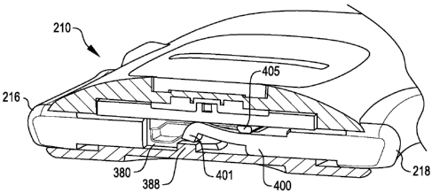
first cam surface that, when translated in a direction
towards the bendable member, raises the bendable member
above the abutment member to release the bendable member.
The snap action actuator may further comprise a second cam
surface that, when translated in a direction away from the
bendable member, raises the bendable member above the
abutment member and returns the bendable member into
engagement with the abutment member under compression. The
device may further comprise a spring that forces the second
cam surface to translate in the direction away from the
bendable member.
BRIEF DESCRIPTION OF THE DRAWINGS
[8] The
features of the present invention which are
believed to be novel are set forth with particularity in the
appended claims. The invention, together with further
features and advantages thereof, may best be understood by
3
CA 02739186 2011-03-28
WO 2009/045780 PCT/US2008/077320
making reference to the following description taken in
conjunction with the accompanying drawings, in the several
figures of which like reference numerals identify identical
elements, and wherein:
[9] FIG. 1 is a perspective view of a first infusion
device embodying certain aspects of the present invention;
[10] FIG. 2 is a schematic representation of the valves
and pump of the device of FIG. 1;
[11] FIG. 3 is an exploded perspective view of the
device of FIG. 1;
[12] FIG. 4 is a sectional view, in perspective, of the
device of FIG.1 showing the pump of the device directly
coupled to an actuator button;
[13] FIG. 5 is a sectional view, in perspective, of the
device of FIG. 1 showing the valves and the valve and
actuation linkages prior to the delivery of a medicament
dose;
[14] FIG. 6 is a sectional view, to an enlarged scale,
illustrating the actuation linkages prior to the delivery of
a medicament dose;
[15] FIG. 7 is a sectional view, like that of FIG. 6,
illustrating the actuation linkages during the delivery of a
medicament dose;
[16] FIG. 8 is a another sectional view, like that of
FIG. 5, illustrating the actuation linkages just after the
delivery of a medicament dose;
[17] FIG. 9 is a perspective view of another infusion
device embodying various aspects of the present invention;
[18] FIG. 10 is a schematic representation of the
valves and pump of the device of FIG. 9 between medicament
4
CA 02739186 2011-03-28
WO 2009/045780 PCT/US2008/077320
dosage delivery and for filling the pump with the
medicament;
[19] FIG. 11 is a schematic representation of the
valves and pump of the device of FIG. 9 during medicament
dosage delivery;
[20] FIG. 12 is an exploded perspective view of the
device of FIG. 9;
[21] FIG. 13 is a perspective view of one component of
the device of FIG. 9;
[22] FIG. 14 is a lengthwise sectional view in
perspective of the device of FIG. 9 and showing a cannula
assembly for use therein in exploded view;
[23] FIG. 15 is a lengthwise sectional view in
perspective of the device of FIG. 9 similar to FIG. 14
showing the cannula assembly in operative association with
the device;
[24] FIG. 16 is a sectional plan view showing the valve
configuration of the device of FIG. 9 during pump filling;
[25] FIG. 17 is a sectional plan view showing the valve
configuration of the device of FIG. 9 during medicament
delivery;
[26] FIG. 18 is a sectional view, in perspective, to an
enlarged scale, showing the actuation linkages of the device
of FIG. 9 prior to medicament dosage delivery;
[27] FIG. 19 is a sectional view like that of FIG. 18,
showing the actuation linkages of the device of FIG. 9
during medicament dosage delivery;
[28] FIG. 20 is a sectional view like that of FIG. 18,
showing the actuation linkages of the device of FIG. 9 after
medicament dosage delivery;
5
CA 02739186 2011-03-28
WO 2009/045780 PCT/US2008/077320
[29] FIG. 21 is a another sectional view, in
perspective, to an enlarged scale, showing the operation of
the actuation linkages;
[30] FIG. 22 is another sectional view like that of
FIG. 21, in perspective, to an enlarged scale, showing the
operation of the actuation linkages;
[31] Fig. 23 is still another sectional view showing
the last dose lock-out and the device pump during normal
medicament delivery actuation;
[32] FIG. 24 is a sectional view, like that of FIG. 23,
showing the last dose lock-out and device pump after normal
medicament delivery;
[33] FIG. 25 is a sectional view, like that of FIG. 23,
showing the last dose lock-out being conditioned for
disabling the actuator upon return of the device pump after
a last normal medicament delivery;
[34] FIG. 26 is a sectional view, like that of FIG. 23,
showing the last dose lock-out disabling the actuator upon a
final medicament delivery;
[35] FIG. 27 is another sectional view, to an enlarged
scale, showing the device pump and the fill port being
blocked during actuation for delivery of medicament; and
[36] FIG. 28 is another sectional view, like that of
FIG. 22, showing the device pump and the fill port being
locked in a blocked condition by the last dose lock-out.
DETAILED DESCRIPTION OF THE INVENTION
[37] Referring now to FIG. 1 it is a perspective view
of a first infusion device embodying certain aspects of the
present invention. The device 10 generally includes an
6
CA 02739186 2011-03-28
WO 2009/045780 PCT/US2008/077320
enclosure 12, a base 14, a first actuator control button 16,
and a second actuator control button 18.
[38] The enclosure 12, as will be seen subsequently, is
formed by virtue of multiple device layers being brought
together. Each layer defines various components of the
device such as, for example, a reservoir, fluid conduits,
pump chambers, and valve chambers, for example. This form of
device construction, in accordance with aspects of the
present invention, enables manufacturing economy to an
extent rendering the device disposable after use.
[39] The base 14 preferably includes an adhesive
coating to permit the device to be adhered to a patient's
skin. The adhesive coating may originally be covered with a
releasable cover that may be pealed off of the base 14 when
the patient endeavors to deploy the device 10. Such
arrangements are well known in the art.
[40] The device 10 may be mated with a previously
deployed cannula assembly. However, it is contemplated
herein that the various aspects of the present invention may
be realized within a device that may be alternatively first
adhered to the patient's skin followed by the deployment of
a cannula thereafter.
[41] The actuator buttons 16 and 18 are placed on
opposites sides of the device 10 and directly across from
each other. This renders more convenient the concurrent
depression of the buttons when the patient wishes to receive
a dose of the liquid medicament contained within the device
10. This arrangement also imposes substantially equal and
opposite forces on the device during dosage delivery to
prevent the device from being displaced and possibly
stripped from the patient. As will be further seen
hereinafter, the concurrent depression of the buttons is
used to particular advantage. More specifically, the
7
CA 02739186 2011-03-28
WO 2009/045780 PCT/US2008/077320
actuator button 16 may serve as a valve control which, when
in a first position as shown, establishes a first fluid path
between the device reservoir and the device pump to support
pump filling, and then, when in a second or depressed
position, establishes a second fluid path between the device
pump and the device outlet or cannula to permit dosage
delivery to the patient. As will be further seen, a linkage
between the control actuator buttons 16 and 18 permits
actuation of the device pump with the actuator control
button 18 only when the second fluid path has been
established by the first actuator control button 16. Hence,
the first actuator control button 16 may be considered a
safety control.
[42] Referring now to FIG. 2, it is a schematic
representation of the valves and pump of the device 10 of
FIG. 1. As may be seen in FIG. 2, the device 10 further
includes a fill port 20, a reservoir 22, a pump 24, and the
cannula 30. The device further includes a first valve 32 and
a second valve 34. Fluid conduit 40 provides a fluid
connection between the fill port 20 and the reservoir 22,
fluid conduit 42 provides a fluid connection between the
reservoir 22 and the first valve 32, fluid conduit 44
provides a fluid connection between the first valve 32 and
the pump 24, fluid conduit 46 provides a fluid connection
between the pump 24 and the second valve 34, and fluid
conduit 48 provides a fluid connection between the second
valve 34 and the device outlet 50. The outlet 50 is arranged
to communicate with the cannula 30.
[43] It may also be noted that the actuator buttons 16
and 18 are spring loaded by springs 36 and 38. The springs
are provided for returning the actuator buttons to the first
position after a dosage is administered.
8
CA 02739186 2011-03-28
WO 2009/045780 PCT/US2008/077320
[44] The pump 24 of the device 10 comprises a piston
pump. The pump 24 includes a pump piston 26 and a pump
chamber 28. In accordance with this embodiment, the actuator
control button 18 is directly coupled to and is an extension
of the pump piston 26.
[45] With further reference to FIG. 2, the device
additionally includes a first linkage 52 and a second
linkage 54. The first linkage is a toggle linkage between
the first valve 32 and the second valve 34. It is arranged
to assure that the second valve 34 does not open until after
the first valve 32 is closed. The second linkage 54 is
between the first actuator button 16 and the second actuator
button 18. It is arranged to assure that the pump does not
pump until after the first valve is closed and the second
valve is opened by the first actuator button 16.
[46] Still further, the second valve 34 is a safety
valve that closes tighter responsive to increased fluid
pressure within fluid conduit 46. This assures that the
liquid medicament is not accidentally administered to the
patient notwithstanding the inadvertent application of
pressure to the reservoir, for example. In applications such
as this, it is not uncommon for the reservoir to be formed
of flexible material. While this has its advantages, it does
present the risk that the reservoir may be accidentally
squeezed as it is worn. Because the second valve only closes
tighter under such conditions, it is assured that increased
accidental reservoir pressure will not cause the fluid
medicament to flow to the cannula.
[47] In operation, the reservoir is first filled
through the fill port 20 to a desired level of medicament.
In this state, the valves 32 and 34 will be as shown. The
first valve 32 will be open and the second valve 34 will be
closed. This permits the piston chamber 28 to be filled
9
CA 02739186 2011-03-28
WO 2009/045780 PCT/US2008/077320
after the reservoir is filled. The cannula 30 may then be
deployed followed by the deployment of the device 10. In
this state, the valves 32 and 34 will still be as shown. The
first valve 32 will be open and the second valve 34 will be
closed. This permits the pump chamber 28 to be filled
through a first fluid path including conduits 42 and 44 as
the piston 24 returns to its first position after each
applied dose.
[48] When the patient wishes to receive a dose of
medicament, the actuator buttons are concurrently pressed.
In accordance with aspects of the present invention, the
linkage 52 causes the first valve 32 to close and the second
valve 34 to thereafter open. Meanwhile, the second linkage
54 precludes actuation of the pump 24 until the first valve
32 is closed and the second valve 34 is opened by the first
actuator button 16. At this point a second fluid path is
established from the pump 24 to the cannula 30 through fluid
conduits 46 and 48 and the outlet 50. The medicament is then
administered to the patient through cannula 30.
[49] Once the medication dosage is administered, the
piston 24, and thus the actuator button 18, is returned
under the spring pressure of spring 38 to its initial
position. During the travel of the piston back to its first
position, a given volume of the liquid medicament for the
next dosage delivery is drawn from the reservoir into the
pump chamber 28 to ready the device for its next dosage
delivery.
[50] Referring now to FIG. 3, it is an exploded
perspective view of the device of FIG. I. It shows the
various component parts of the device. The main component
parts include the aforementioned device layers including the
base layer 60, the reservoir membrane or intermediate layer
62, and the top body layer 64. The base layer is a
CA 02739186 2011-03-28
WO 2009/045780 PCT/US2008/077320
substantially rigid unitary structure that defines a first
reservoir portion 66, the pump chamber 28, and valve sockets
68 and 70 of the first and second valves respectively. The
base layer 60 may be formed of plastic, for example. The
reservoir membrane layer 62 is received over the reservoir
portion 66 to form the reservoir 22 (FIG. 2). A valve seat
structure 72 is received over the valve sockets 68 and 70 to
form the first and second valves 32 and 34 (FIG.2)
respectively. A rocker 74 is placed over the valves seat
structure 72 to open and close the valves as will be seen
subsequently. The pump actuator button 18 carries the pump
piston that is received within the pump chamber 28. The pump
actuator button 18 also carries a cam cylinder 76 with a
lock tube 78 therein that form a portion of the second
linkage 54 (FIG. 2). The spring 38 returns the actuator
button 18 to its first position after each dosage delivery.
[51] The first actuator control button carries a valve
timing cam 80 that rocks the rocker 72. The button 16
further carries a cam cylinder 82 and a cam pin 84 that is
received into the cam cylinder 82. The spring 36 returns the
actuator button 16 to its first position after each dosage
delivery. The top body layer 64 forms the top portion of the
device enclosure. It receives a planar cap 86 that completes
fluid paths 85 partially formed in the top layer 64. Lastly,
a needle 88 is provided that provides fluid coupling from
the cannula (not shown) to the outlet of the device 10.
[52] FIG. 4 shows a sectional view, in perspective, of
the device of FIG.1. More specifically, the figure shows
details of the piston pump 24 within the device 10. Here, it
may be seen that the piston 26 of the piston pump 24 is
received within the pump chamber 28 that is formed in the
base layer 60 of the device. The piston 26 may further be
seen to be an extension of the actuator button 18. An 0-ring
11
CA 02739186 2011-03-28
WO 2009/045780 PCT/US2008/077320
90 provides a seal between the pump chamber 28 and the
piston 26. The spring 38 returns the actuator button 18 to
its shown first position after each dosage delivery.
[53] FIG. 5 is a sectional view, in perspective, of the
device of FIG. 1 showing the valves 32 and 34 and the valve
and actuation linkages prior to the delivery of a medicament
dose. The valves will first be described. First, it may be
noted that the valve seat structure 72 is received within
the valve sockets 68 and 70. The valve seat structure 72
includes valve seats 92 and 94 that are received within the
valve sockets 68 and 70 respectively. Each of the seats 92
and 94 has a widened portion 96 and 98, respectively, that
cause the seats to be more tightly seated within sockets 68
and 70 in response to increased fluid pressure in the
downward direction. As previously described, this protects
against the potential effects of accidental medication
delivery due to external pressure being applied to the
reservoir of the device.
[54] The rocker 74 opens and closes the valves 32 and
34. It is under control of the timing cam 80 carried by the
first actuator control button 16. As the control button 16
is moved laterally, the cam 80 causes the rocker 74 to pivot
and to apply pressure to one or the other of the valve seats
92 or 94. The shape of the cam surfaces on the rocker 74 and
the cam 80 assure that the valve 34 will not open until the
valve 32 closes. The cam 80 and rocker 74 thus form the
first linkage 52 shown in FIG. 2.
[55] While the cam 80 and rocker 74 are operating the
valves 32 and 34 under timing control provided by the first
linkage 52, the second linkage 54 is controlling when the
pump may displace liquid medicament form the pump chamber 28
to the device outlet and cannula. FIGS. 5-8 show details of
the second linkage.
12
CA 02739186 2011-03-28
WO 2009/045780
PCT/US2008/077320
[56] As may be seen in FIGS. 5 and 6, the second
linkage includes the cam cylinder 76, the lock tube 78, the
outer cam cylinder 82, and the cam pin 84. The cam cylinder
is integral with the second actuator control button 18 and
the outer cam cylinder 82 is integral with the first
actuator control button. The second linkage 54 further
includes a lock cylinder 100. The foregoing are disposed in
a bore 102 formed in the base layer 60 of the device.
[57] When the actuator buttons are in their first
position as shown in FIG. 6, the end of the lock tube 78
abuts the end of the lock cylinder 100. The lock cylinder
includes ears 104. When a dosage delivery is desired, the
concurrent pushing of the buttons 16 and 18 causes the outer
cam cylinder 82 to slide over the lock cylinder 100 first
and then the cam cylinder 76 to slide over the lock tube 78.
The sliding of the outer cam cylinder 82 over the lock
cylinder 100 causes the first valve to close and the second
valve to open. When this is accomplished, the cam cylinder
76 is then permitted to slide over lock tube 78 to cause the
piston 26 to move through the pump chamber 28. This
displaces the liquid medicament in the pump chamber 28 for
delivering the medicament to the cannula 30 and the patient.
[58] FIG. 7 illustrates the manner in which the outer
cam cylinder 82 slides along the lock cylinder 100. It may
first be noted that the cam pin 84 has a reduced diameter
portion creating an annular space 106 between the pin 84 and
the lock cylinder 100. The outer cam cylinder 82 engages the
pin at a flange 108 of the pin 84. This engagement will
cause the pin 84 to move with the outer cam cylinder 82. The
pushing of the first actuator button 16 will cause the outer
cam cylinder 82 to engage the ears 104 of the lock cylinder
100 while at the same time, the end of the pin 84 moves into
the lock tube 78. Eventually, the ears 104 are depressed
13
CA 02739186 2011-03-28
WO 2009/045780 PCT/US2008/077320
enough by the outer cam cylinder 82 as the end of the pin 84
clears the end of the depressed lock cylinder 100 to permit
the ears 104 to enter space 106. This occurs with a snap
sound and feel as it occurs suddenly. The outer cam cylinder
82 is now free to slide its complete travel distance over
the lock cylinder 100. The valve 32 has now been closed and
the valve 34 has been opened.
[59] The snap action of the actuator buttons 16 and 18
provides positive assurance to the patient that a dosage of
medicament was delivered. Also, because the snap action only
occurs when the pump actuator button 18 completes it full
travel, the patient will also know that a full dosage was
delivered.
[60] After the outer cam cylinder 82 has completed its
travel over the lock cylinder 100, the ears 104 will be
displaced sufficiently into space 106 to permit the cam
cylinder 76 to clear the end of the lock cylinder 100 and
slide over the lock tube 78. The condition of the second
linkage 54 at this time is shown in FIG. 8. As previously
described, as the cam cylinder 76 slides over the lock tube
78, the pump 24 is actuated to deliver the medicament to the
patient.
[61] Referring now to FIG. 9, it is a perspective view
of another infusion device embodying various aspects of the
present invention. The device 210 generally includes an
enclosure 212, a base 214, a first actuator control button
216, and a second actuator control button 218.
[62] The enclosure 212 is formed by virtue of multiple
device layers being brought together. Each layer defines
various components of the device such as, for example, a
reservoir, fluid conduits, pumps, and valve chambers, for
example. This form of device construction, in accordance
with aspects of the present invention, enables manufacturing
14
CA 02739186 2011-03-28
WO 2009/045780 PCT/US2008/077320
economy to an extent rendering the device disposable after
use.
[63] The base 214 preferably includes an adhesive
coating to permit the device to be adhered to a patient's
skin. The adhesive coating may originally be covered with a
releasable cover that may be pealed off of the base 214 when
the patient endeavors to deploy the device 210. Such
arrangements are well known in the art.
[64] As will also be seen subsequently, the device 210
may be mated with a previously deployed cannula assembly.
However, it is contemplated herein that the various aspects
of the present invention may be realized within a device
that may be alternatively first adhered to the patient's
skin followed by the deployment of a cannula thereafter.
[65] As in the previous embodiment, the actuator
buttons 216 and 218 are placed on opposites sides of the
device 210 and directly across from each other. This again
renders more convenient the concurrent depression of the
buttons when the patient wishes to receive a dose of the
liquid medicament contained within the device 210. This
arrangement also imposes substantially equal and opposite
forces on the device during dosage delivery to prevent the
device from being displaced and possibly stripped from the
patient. As will be further seen hereinafter, the concurrent
depression of the buttons is used to particular advantage.
More specifically, the actuator button 216 may serve as a
valve control which, when in a first position as shown,
establishes a first fluid path between the device reservoir
and the device pump to support pump filling, and then, when
in a second or depressed position, establishes a second
fluid path between the device pump and the device outlet or
cannula to permit dosage delivery to the patient. As will be
further seen, a linkage between the control actuator buttons
CA 02739186 2011-03-28
WO 2009/045780 PCT/US2008/077320
216 and 218 permits actuation of the device pump with the
actuator control button 218 only when the second fluid path
has been established by the first actuator control button
216. Hence, the first actuator control button 216 may be
considered a safety control.
[66] With continued reference to FIG.9, it may be
further noted that the device 210 also includes a tactile
indicator 260 that represents the volume of the liquid
medicament delivered by the device with each actuation of
the pump 224. The tactile indicator is carried by the pump
actuator button 218 and takes the form of a plurality of
distinct raised features or bumps 262 and 264.
Alternatively, the tactile indicator may take the form of
one or more distinct relieved portions. Each bump 262 and
264 may correspond to a single unit of medicament. Hence, in
this embodiment, the bumps 262 and 264 indicate that the
device delivers two units of medicament with each actuation
of the pump.
[67] The tactile indicator 260 being carried on the
pump actuator control button 218 provides a very significant
feature and advantage. As will be seen subsequently, the
pump actuator button 218 has an integral extension that
forms the piston 226 of the piston pump 224 as represented
in FIG. 10 to be described hereinafter. It will also be seen
that the piston chamber 228 is formed in a component of the
device that may be used in devices delivering dosage amounts
other than two units. The component may be common to all
such devices because it would have a fixed piston chamber
length and the dosage amount is determined by the throw of
the pump piston 226. Each piston throw is integral to the
part and corresponds to a respective given dosage amount.
Each pump actuator button for a given dosage amount may have
then be provided with a corresponding tactile indicator.
16
CA 02739186 2011-03-28
WO 2009/045780 PCT/US2008/077320
Hence, if a tactile indicator indicates a dosage amount of
two units, for example, it is assured that that is the
medicament amount delivered with that particular pump
button. Further, this arrangement is advantageous from a
manufacturing standpoint because the actuator buttons for
the various dosage size devices cannot be confused with each
other.
[68] Referring now to FIGS. 10 and 11, they are
schematic representations of the valves and pump of the
device of FIG. 9 between medicament dosage filling (FIG. 10)
and medicament dosage delivery (FIG. 11) As may be seen in
FIGS. 10 and 11, the device 210 further includes a reservoir
222, a pump 224, and the cannula 230. The device further
includes a shuttle valve 231 forming a first valve 232
defined by 0-rings 233 and 235 and a second valve 234
defined by 0-rings 237 and 239. Although 0-rings are used
herein to form seals, other types of valve construction may
best employ forms of seals other than 0-rings without
departing from the invention. Fluid conduit 240 extends
between the valves 232 and 234. A fluid conduit 242 provides
a fluid connection between the reservoir 222 and the shuttle
valve 231 and fluid conduit 244 provides a fluid connection
between the shuttle valve 231 and the pump 224. A further
fluid conduit 246 provides a fluid connection between the
shuttle valve 231 and the device outlet 250. The outlet 250,
in the form of a needle, is arranged to communicate with the
cannula 230.
[69] It may also be noted that the actuator buttons 216
and 218 are spring loaded by springs 236 and 238. The
springs are provided for returning the actuator buttons to
the first position after a dosage is administered.
[70] The pump 224 of the device 210 comprises a piston
pump. The pump 224 includes a pump piston 226 and a pump
17
CA 02739186 2011-03-28
WO 2009/045780 PCT/US2008/077320
chamber 228. In accordance with this embodiment, the
actuator control button 218 is directly coupled to and is an
extension of the pump piston 226.
[71] With further reference to FIGS. 10 and 11, the
device additionally includes a first linkage 252 and a
second linkage 254. The first linkage is formed by the
shuttle bar 241 of the first valve 232 and the second valve
234. It is arranged by separating the valves 232 and 234 be
a distance that assures that the second valve 234 does not
open until after the first valve 232 is closed. The second
linkage 254 is between the first actuator button 216 and the
second actuator button 218. It is arranged to assure that
the pump 224 does not pump until after the first valve 232
is closed and the second valve 234 is opened by the first
actuator button 216.
[72] Still further, the second valve 234 is a safety
valve that assures that the liquid medicament is not
accidentally administered to the patient notwithstanding the
inadvertent application of pressure to the reservoir, for
example. In applications such as this, it is not uncommon
for the reservoir to be formed of flexible material. While
this has its advantages, it does present the risk that the
reservoir may be accidentally squeezed as it is worn.
Because of the second valve 234, it is assured that
accidental reservoir pressure will not cause the fluid
medicament to flow to the cannula.
[73] In operation, the pump chamber 228 is first filled
as the actuator button 218 returns to the first position
after having just delivered a medicament dosage. In this
state, the shuttle valve 231 is set so that the first valve
232 will be open (the reservoir 222 communicates with the
fluid conduit 240) and the second valve 234 will be closed
(the conduit 246 is closed off from fluid conduit 240). This
18
CA 02739186 2011-03-28
WO 2009/045780 PCT/US2008/077320
establishes a first fluid path from the reservoir 222 to the
pump 224 through conduits 242, 240 and 244 that permits the
piston chamber 228 to be filled by the reservoir as the
actuator button is returned to its first position under the
influence of the spring 238.
[74] When the patient wishes to receive another dose of
medicament, the actuator buttons are concurrently pressed.
In accordance with aspects of the present invention, the
linkage 252 causes the first valve 232 to close and the
second valve 234 to thereafter open. Meanwhile, the second
linkage 254 precludes actuation of the pump 224 until the
first valve 332 is closed and the second valve 334 is opened
by the first actuator button 216. At this point a second
fluid path is established from the pump 224 to the cannula
30 through fluid conduits 244, 240 and 246 and the outlet
250. The medicament is then administered to the patient
through cannula 30.
[75] Once the medication dosage is administered, the
piston 224, and thus the actuator button 218, is returned
under the spring pressure of spring 238 to its initial
position. During the travel of the piston back to its first
position, a given volume of the liquid medicament for the
next dosage delivery is drawn from the reservoir into the
pump chamber 228 as described above to ready the device for
its next dosage delivery.
[76] Referring now to FIG. 12, it is an exploded
perspective view of the device of FIG. 9. It shows the
various component parts of the device 210. Like the device
10 of FIG. 1, the device 210 is constructed in device layers
including a base layer 280, an intermediate layer 282, and
the top body layer 284.
[77] As may also be seen in FIG. 13, the base layer 280
is a substantially rigid unitary structure that defines a
19
CA 02739186 2011-03-28
WO 2009/045780 PCT/US2008/077320
first reservoir portion 286, the pump chamber 228, and a
valve chamber 290 for the first and second valves 232 and
234. The base layer 280 may be formed of plastic, for
example.
[78] The valve chamber 290 is arranged to receive the
valve shuttle bar 241 carried by and extending from the
first actuator button 216. 0-rings 233, 235, 237, and 239
are arranged to be seated on the shuttle bar 241 to form the
first and second valves 232 and 234 respectively (FIG.
10).The actuator button 216 also carries a first portion 292
of the second linkage 254 (FIG. 10). The second linkage is
received within a suitably configured bore 295 formed in the
base layer 280 and will be described subsequently.
[79] The pump actuator button 218 carries the pump
piston 226 and a second portion 294 of the second linkage
254. The pump piston 226 is arranged to be received within
the pump chamber 228 and the second portion 294 of the
second linkage 254 is arranged to be received within the
bore 295 for interacting with the first portion 292. 0-rings
300 and 302 are arranged to be seated on the piston 226 to
provide a seal against leakage and to prevent external
contaminants from entering the piston chamber. The base
layer 280 further includes fluid channels 304 that serve to
form the fluid conduits illustrated in FIG. 10. Finally,
springs 306 and 308 are arranged to spring load the actuator
buttons 216 and 218.
[80] The intermediate layer 282 is formed of flexible
membrane material. A portion 296 of the intermediate layer
is received over the reservoir portion 286 to form the
reservoir 222 (FIG. 10). A rigid plate 310 is arranged to be
adhered to the portion 296 of the reservoir. Because the
layer 282 is flexible membrane, it will move as the
reservoir is filled and emptied. The rigid plate 310 will
CA 02739186 2011-03-28
WO 2009/045780 PCT/US2008/077320
then move with it. The plate includes an eyelet 312
dimensioned to receive an elongated web 314 that forms a
part of a medicament level indicator to be described
hereinafter. The web 314 carries an indicator line or
feature 316.
[81] The top layer 284 is arranged to be received over
the intermediate layer 282 and adhered to the base layer. It
includes a panel 320 having a view window 318 through which
the medicament level indicator line may be observed.
[82] Lastly with respect to FIG. 12, it may be noted
the device 210 further includes a pin 322. The pin 322 is a
locking pin that is employed to lock the actuator buttons
after a last medicament dose is delivered. It also serves to
maintain the device fill port, to be described subsequently,
in a blocked condition after a last medicament dose is
delivered.
[83] Referring now to FIGS. 14 and 15, they are
lengthwise sectional views, in perspective, of the device of
FIG. 9 along with a cannula assembly that may be deployed in
the device. Fig. 14 illustrates the previously described
layered structure of the device 210 including device layers
280, 282, and 284. As may also be noted in FIG. 14, the
device includes a port for receiving a cannula assembly 340.
The cannula assembly has a base 342, a generally cylindrical
docking structure 344, and a cannula 346. The docking
structure 344 is arranged to be received by the port 330
(FIG. 15) after the cannula assembly 340 is applied to the
patient's skin with the cannula projecting beneath the
patient's skin. The device includes a needle 348 that
projects through a septum 350 of the device when the cannula
assembly 340 is received by the port 330. This completes the
fluid path from the reservoir 222 to the cannula 346. For a
more detailed description of such a cannula assembly and the
21
CA 02739186 2015-01-28
device that utilizes the same, reference may be had to co-
pending United States Application Serial No. 11/803,007,
filed May 11, 2007, and entitled INFUSION ASSEMBLY.
[84] FIGS. 14 and 15 also clearly illustrate a
medicament level indicator embodying the present invention.
The rigid plate 310 forms a moveable wall that moves as the
medicament volume increases and decreases within the
reservoir. The elongated web 316 is preferably formed from a
non-elastic, non-compressible, elongated material. It has a
first end 352 and a second end 354. The web is fixed at the
first end 352 with respect to the rigid plate 310 of the
reservoir 222 and is arranged to move in a first plane
generally perpendicular to the rigid plate 310 intermediate
the first and second ends 352 and 354. Because the web 316
is fixed at the first end 352 and free to move within the
eyelet 312, its second end 354 will move in linear movement
in a second plane substantially parallel to the rigid member
and transverse to the first plane.
[85] As previously mentioned, a panel 320 of the top
layer 284 has a window opening 318 to render the medicament
level indicia viewable. The cover panel 320 forms a guide
channel 356 that receives and confines the web second end to
guide the web for linear movement in the second plane
substantially transverse to the first plane. As the
reservoir is filled or emptied, a glance through the window
318 will provide an indication of the level of the
medicament in the reservoir 222.
[86] Referring now to FIG. 16, it is a sectional plan
view showing the valve configuration of the device 210 of
FIG. 9 during medicament filling of the pump chamber 228
immediately after a dosage delivery. Here, it may be clearly
22
CA 02739186 2011-03-28
WO 2009/045780 PCT/US2008/077320
seen that the first actuator button 216 has an extension
comprising the shuttle bar 241 of the valves 232 and 234.
Above the valves are the conduits from the reservoir, from
the pump, and to the cannula. More particularly, the conduit
242 is in fluid communication with the reservoir 222 (FIG.
10), the conduit 244 is in fluid communication with the
pump, and the conduit 246 is in fluid communication with the
cannula. The valves are shown with the first valve 232
opened and not blocking the reservoir conduit 242, and the
second valve 234 closed and blocking the conduit 246 to the
cannula. This permits medicament to flow from the reservoir
through conduit 242 and to the pump chamber 228 through
conduit 244 as the actuator button 216 returns to its first
position. Hence, the pump chamber is filled and ready for
the next dosage delivery.
[87] Referring now to FIG. 17, it is a sectional plan
view showing the valve configuration of the device 210 of
FIG. 9 during medicament delivery. Here, the valves are
shown with the first valve 232 closed and blocking the
reservoir conduit 242, and the second valve 234 open
permitting medicament to flow from the pump through conduit
244 and to the cannula through conduit 246. As previously
mentioned, the first and second valves 232 and 234,
respectively, are spaced apart so that conduit 242 is
blocked before conduit 246 is opened.
[88] FIGS. 18-22 show details of the operation of the
second linkage 254 of the device 210. Through this
discussion, simultaneous reference to more than one drawing
figure may be necessary. As may be seen FIG. 18, the first
actuator button 216 has an extension 380 that terminates in
a block 382 having a first ramp surface 384 and a second
ramp surface 386. When the device 210 is actuated, the
button 216 is concurrently depressed with pump button 218.
23
CA 02739186 2011-03-28
WO 2009/045780 PCT/US2008/077320
It and its extension 380 and bloc 382 are free to move to
the right. As seen in FIGS. 18 and 21, the pump actuator
button 218 has parallel extensions 400 and 402 which are
joined and separated be a rod member 404. As seen in FIG.
18, the extension 400 abuts an abutment 388 which it must
clear to be able to move to the left. As shown in FIG. 21,
as the button 216 is depressed, its extension 380 moves to
the right causing the first ramp surface to engage the rod
member 404. Continued movement of the button causes the rod
member 404 to rise up under the first ramp surface 384 which
in turn causes the extension 400 to begin to move slightly
to the left and bend upward about rib 405. Eventually, the
rod member 404 rides up the length of the first ramp 384
causing the end 401 of extension 400 to clear the abutment
388 as shown in FIG. 19. The pump button 216 is now able to
move freely to the left. When the end 401 of extension 400
totally clears the abutment 388, it will snap behind the
abutment 388 as shown in FIG. 20 and become temporarily
locked. Meanwhile, as shown in FIG. 22, the rod member 404
has traversed down the second ramp surface 386. The buttons
216 and 218 are now fully depressed.
[89] Hence, from the above, it may be seen that the
pump button 218 could not at first move freely while the
first actuator button 216 which operates the valves could.
As a result, the pump actuation lags behind the valve
actuation causing the first valve 232 (FIG. 10) to be closed
and the second valve 234 to be opened, establishing a
medicament delivery flow path to the cannula, before the
pump is able to begin pumping the medicament to the patient.
Because this operation occurs quickly, it appears to the
patient that both actuator buttons are moving at the same
rate.
24
CA 02739186 2011-03-28
WO 2009/045780 PCT/US2008/077320
[90] When the extension 400 of the pump button clears
the abutment 388, it becomes locked in a snap action. As in
the previous embodiment, this provides positive feedback to
the patient that a dosage of medicament was delivered as
desired. It also causes a full dose to be delivered. By
virtue of the snap action of the pump actuator, only full
doses may be administered.
[91] When the medicament has been delivered, the spring
loading of the actuator buttons returns the buttons to their
first or initial position. During this time, the same timing
provided by the block 382 is used for recharging the pump.
More specifically, ramp 366 unlatches the end 401 of
extension 400 by lifting rod member 404 so that 246 is
closed and conduit 242 is opened before the pump is returned
by the spring to its initial position. This assures that
the pump does not pull medicament from the patient but only
from the reservoir. As the piston 226 of the piston pump
224 returns, a full dose of the medicament is drawn up into
the piston chamber 228 to ready the device for the next
dosage delivery.
[92] FIGS. 23 and 24 show the operation of the piston
pump 224 in greater detail. Also shown is a last dose lock-
out 420 that will be described subsequently. Here it may be
seen that the piston 226 of pump 224 is an extension of the
pump actuator button 218. Also, it may be seen that the 0-
rings 300 and 302 seal the piston 226 and the chamber 228.
The double 0-rings both prevent leakage of medicament from
the camber 228 and prevent outside contaminants from
entering the chamber 228.
[93] When the pump chamber is filled with medicament as
the actuator button is returned from the second position
shown in FIG. 24 to the first or initial position shown in
FIG. 23 after a dosage delivery, medicament flows from the
CA 02739186 2011-03-28
WO 2009/045780 PCT/US2008/077320
reservoir, through a conduit 307 (FIG. 13), through a
diaphragm chamber 424 and through the conduit 244 to the
pump chamber 228. The chamber 424 is defined by a diaphragm
422 formed of flexible membrane material. The diaphragm 422
includes an extension which captures the pin 322, previously
shown in the exploded view of FIG. 12. As long as the
reservoir has medicament, and hence is not empty, the
diaphragm 422 is not affected. In this state, the button 216
is free to be actuated.
[94] As may be noted, the pin is L-shaped at end 323
with an L-extension 428. A capture ramp 430, integral with
the actuator button, passes adjacent to the pin 322 and over
the L-extension 328. This occurs when the actuator button is
depressed as long as the reservoir has sufficient medicament
to provide at least one more dosage delivery.
[95] Reference may now be had to FIGS. 25 and 26 as the
operation of the last dose lock-out 420 is described. When
the reservoir has insufficient medicament to support
delivery of another dose of medicament, and during the
return of the actuator button 218 after what will be the
last dose delivered, a negative pressure is created in the
diaphragm chamber 424. This causes the diaphragm 422 to be
drawn into the chamber 424 due to the absence of liquid
medicament in the chamber 424. As the diaphragm 422 is drawn
into the chamber 424, the pin 322 is drawn upward with the
diaphragm 422 where it engages an abutment 432 connected to
the ramp extension 430. The pin 322 is now caused to be
captured between the ramp 430 and the abutment 432. The
button 216 is now only partially returned to its first
position whereas the pump actuator button 218 is free to
fully return to its initial position. Upon the next
attempted actuation of the device, the L-extension will ride
up the ramp 430 and fall into a locked position between the
26
CA 02739186 2015-01-28
ramp 430 and a shoulder 434 formed in the actuator button
216. The button is now locked and cannot be returned to its
first position. The pump actuator button 218 will also be
locked in its second position as shown in FIG. 26. This is
due to the fact that the first button 216 is not able to
return from its second position which, as shown in FIG. 20,
causes the end 401 of the extension 400 of the pump actuator
218 be locked between the abutment 388 and actuator button
216. Hence, the device 210 is now locked and cannot be
reused.
[96] Referring now to FIGS. 27 and 28, they illustrate
a further aspect of the last dose lock-out. Before the
device 210 can be used to deliver a medicament, its
reservoir must be filled with a medicament. To this end, the
device 210 is provided with a fill port 440 that
communicates with the reservoir. When the device 210 is
filled with medicament, the actuator buttons 216 and 218 are
in their initial positions. The first actuator button 216
further includes another extension 442 which does not cover
the fill port 440 when the actuator button 216 is in its
initial position. However, when the actuator button 216 is
in its fully actuated second position, it does block the
fill port 440 as seen in FIG. 28. When the last dose lock-
out has the locked the device, the actuator button 216 is
left in its fully actuated second position. As a result, the
last dose lock-out not only locks both actuator buttons 216
and 218 to disable the device 210, it also blocks the fill
port 440 to further render the device disabled.
[97] While particular embodiments
have been shown and described, modifications may
be made. For example, instead of manual actuation and
spring loaded return of the valves used herein,
constructions are possible which perform in a reversed
27
CA 02739186 2015-01-28
manner by being spring actuated and manually returned.
28