Note: Descriptions are shown in the official language in which they were submitted.
CA 02751568 2016-09-21
WO 2010/091225 PCMIS2010/023282
1 TITLE
2 Interlocking Shape For Use in Construction Members
3
4
7
8
9 BACKGROUND
The concept of interlocking shapes is well known in the art of construction
11 members. Most of the known interlocking shapes have two shapes that
interconnect in
12 some way such as a tongue in groove. The known types of interlocking
shapes are
13 generally male-female connections. There are a wide variety of types of
these
14 connections in a wide variety of applications and shapes. However, these
known shapes
have the disadvantage that two shapes are needed to form the interlock,
limiting the
16 configurations and increasing the costs for the creation of a male and a
female part.
17 The foregoing example of the related art and limitations related
therewith are
18 intended to be illustrative and not exclusive. Other limitations of the
related art will
19 become apparent to those of skill in the art upon a reading of the
specification and a study
of the drawings.
2]. SUMMARY
22 An aspect of the present invention is to provide a shape that can
interlock with
23 itself to form a interlocking racking system. Another aspect of the
present invention is to
24 provide a roof flashing and standoff system that can support the novel
interlock racking
system.
1
CA 02751568 2011-08-04
WO 2010/091225 PCT/US2010/023282
1 An aspect of the present invention is to provide a shape that can
interlock with
2 itself to form an interlocking racking system, wherein each bracket has
two opposing
3 recesses.
4 Another aspect of the present invention is to provide a mounting clip
that can be
attached to a solar panel and then clipped into a recess in a bracket.
6 The present invention discloses a set of shapes that function as both
the male and
7 female part of the interlock, allowing a single shape to interlock with
its identical shape.
8 An embodiment of the present invention has a curved exterior for added
esthetic
9 appearance.
The shape is a face with a recess and at least one exterior surface. The
recess has
11 two upper facing surfaces and two lower facings surfaces. The exterior
surface meets the
12 upper facing surface, forming an edge. The two lower facings surfaces
are set back from
13 the upper facing surfaces, forming a lip, and interlocking the lips of
the two faces form
14 the interlock. Also disclosed is a number of devices for mounting
members made with
the faces on at least one surface and for attaching things to a member with
the face on at
16 least one surface.
17 One application uses the watertight standoff system to support
interlocking racks
18 which hold solar panels off the surface of a roof.
19 The bracket shape is a hexagon with a pair of opposing recesses. Each
recess has
two upper facing surfaces and two lower facing surfaces. The exterior surface
meets the
21 upper facing surface, forming an edge. The two lower facings surfaces
are set back from
22 the upper facing surfaces, forming a lip, and interlocking the lips of
the two faces forms
23 the interlock of two brackets. Also disclosed is a mounting clip that
attaches to a solar
24 panel, then clips into a recess.
In addition to the exemplary aspects and embodiments described above, further
26 aspects and embodiments will become apparent by reference to the
accompanying
27 drawings forming a part of this specification wherein like reference
characters designate
28 corresponding parts in the several views.
2
CA 02751568 2011-08-04
WO 2010/091225 PCT/US2010/023282
1
2 BRIEF DESCRIPTION OF THE DRAWINGS
3 Fig. 1 is a top plan view of a support post with an interlocking face on
all four sides and a
4 single face of a second support post interlocked therewith.
Fig. 2 is a side perspective view of the support post shown in Fig. 1.
6 Fig. 3 is a top plan view of the Fig. 1 support post showing dimensions.
7 Fig. 4 is a top plan view of an alternate embodiment of the support post
with the
8 interlocking face having flat surfaces.
9 Fig. 5 is a top plan view of an alternate embodiment of the support post
with squared
ends.
11 Fig. 6 is a top perspective view of another alternate embodiment of a
support post with
12 threaded facing surfaces to allow a bolt in the threads to be used to
attach items to
13 the support post.
14 Fig. 7 is a side perspective view of a threaded support post.
1 5 Fig. 8 is a top plan view of a single face member alternate embodiment.
16 Fig. 9 is a side perspective view of the single face member shown in
Fig. 8
17 Fig. 10 is a top plan view of an alternate embodiment that can be used
as a frame for a
18 solar panel next to a thermal exchange panel.
19 Fig. 11 is a side perspective view of the Fig. 10 embodiment.
Fig. 12 is a top plan view of another embodiment that can be used as a rack
for a panel.
21 Fig. 13 is a side perspective view of the Fig. 12 embodiment.
22 Fig. 14 is a side perspective view of a central Fig. 1 embodiment
coupled to two Fig. 10
23 type embodiments.
24 Fig. 15 is a top pan view of a support post interlocked with a frame
member.
Fig. 16 is a perspective view of a sliding anchor suited to fit into an
interlocking face of a
26 support post.
2 7 Fig. 17 is a perspective view of a connector for joining the
interlocking faces of two
28 support posts at right angles.
3
CA 02751568 2011-08-04
WO 2010/091225 PCT/US2010/023282
1 Fig. 18 is a perspective view of another connector for joining the
interlocking faces of
2 two support posts at right angles.
3 Fig. 19 is a perspective view of the Fig. 1 support post with a Fig. 17
connector installed.
4 Fig. 20 is an exploded view of a stand off and flashing to attach a
support post to a roof or
other surface.
6 Fig. 21 is a cross section of the stand off and flashing of Fig. 22.
7 Fig. 22 is a cross section of another stand off and flashing.
8 Fig. 23 is an exploded view of the stand off of Fig. 22.
9 Fig. 24 shows the Fig. 23 stand off initially installed.
Fig. 25 shows the Fig. 24 stand off ready to accept a support post.
11 Fig. 26 shows the Fig. 25 stand off attached to the stand off.
12 Fig. 27 is a front plan view of a base for a bracket.
13 Fig. 28 is a side perspective view of the Fig. 27 bracket assembled.
14 Fig. 29 is a top plan view of the Fig. 28 bracket.
Fig. 30 is a side elevation view of the Fig. 28 bracket.
16 Fig. 31 is a front plan view of the Fig. 28 bracket ready to receive a
support post.
17 Fig. 32 is the same view as Fig. 31 with the support post partially
installed.
18 Fig. 33 is the same view as Fig. 32 with the support post installed on
the bracket.
19 Fig. 34 is a top plan view of the bracket of Fig. 35 with the support
post attached.
Fig. 35 is a bracket for attaching into a face in a conventional male-female
interaction.
21 Fig. 36 is a cross sectional view of a stand off supporting the
bracket/support post of Fig.
22 34.
23 Fig. 37 is the same view as Fig. 1 with a solar panel frame ready to
mount to a jaw.
24 Fig. 38 is a side perspective view of the Fig. 37 embodiment.
Fig. 39 is a side perspective view of the Fig. 11 style frame in use.
26 Fig. 40 is a front elevation view of a stand off supporting a variety of
rack configurations.
27 Fig. 41 is a front elevation view of an alternative stand off supporting
a variety of rack
28 configurations.
4
CA 02751568 2011-08-04
WO 2010/091225
PCT/US2010/023282
1 Fig. 42 is a top perspective view of a stand off being installed.
2 Fig. 43 is a top perspective view of a row of stand offs on a roof.
3 Fig. 44 is a top plan view of a support post (bracket) with the
interlocking face on
4 opposing sides.
Fig. 45 is a side perspective view of a pair of interlocked brackets.
6 Fig. 46 is a front elevation view of a bolt anchor securing the bracket.
7 Fig. 47 is a front elevation view of a mounting clip.
8 Fig. 48 is a front elevation view of a bracket jaw holding the mounting
clip of Fig. 47.
9 Fig. 49 is a top plan view of the mounting clip before it was formed.
Fig. 50 is a top perspective view of the clip of Fig. 47 in a jaw.
11 Fig. 51 is a side elevation view of a cabinet mounted to a wall via a
pair of single jaw
12 brackets.
13 Fig. 52 is the same view as Fig. 51 before mounting.
14 Fig. 53 is the same view as Fig. 53 with the jaws inter-connected just
before a final push
is used to interlock the jaws.
16 Fig. 54 is a cross sectional exploded view of a stand off with a double
bolt stud.
17 Fig. 55 is a bottom perspective view of the double bolt stud.
18 Fig. 56 is a top perspective view of the stand off of Fig. 54 supporting
a W spring base.
19 Fig. 57 is a top perspective view of the stand off of Fig. 54 supporting
a T slide.
Fig. 58 is a top perspective view of a four jaw support post with a snap in
conduit clamp
21 installed.
22 Fig. 59 is a top perspective view of the two vertical clips of the
conduit clamp being
23 installed in the jaw.
24 Fig. 60 is a front elevation view of a wide mouth four jaw support post.
Fig. 61 is the same view as Fig. 60 with a four jaw support post received in
the wide
26 mouth.
27 Fig. 62 is a top perspective view of a sign post received in the wide
mouth four jaw
28 support post.
5
CA 02751568 2011-08-04
WO 2010/091225 PCT/US2010/023282
1 Fig. 63 is a top perspective view of a smaller four jaw support post in
the wide mouth
2 four jaw support post.
3 Fig. 64 is a front elevation view of a triangular three jaw support post.
4 Fig. 65 is a side elevation view of a roof anchor.
Fig. 66 is a partial sectional view of the roof anchor installed through a
metal roof.
6 Fig. 67 is a partial sectional view of the roof anchor installed through
a roof tile.
7 Fig. 68 is a bottom perspective view of a bolt embodiment of the roof
anchor of Fig. 65.
8 Fig. 69 is a bottom perspective view of a threaded hole embodiment of the
roof anchor of
9 Fig. 65.
1 0 Before explaining the disclosed embodiment of the present invention in
detail, it
11 is to be understood that the invention is not limited in its application
to the details of the
12 particular arrangement shown, since the invention is capable of other
embodiments.
13 Exemplary embodiments are illustrated in referenced figures of the
drawings. It is
14 intended that the embodiments and figures disclosed herein are to be
considered
illustrative rather than limiting. Also, the terminology used herein is for
the purpose of
16 description and not of limitation.
17
18 DETAILED DESCRIPTION OF THE DRAWINGS
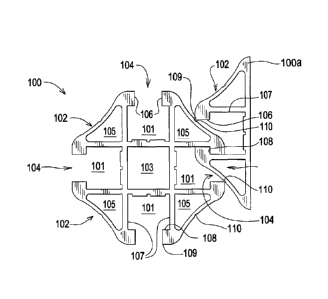
19 Referring first to Figure 1, support post 100 has four recesses 101 and
four outer
surfaces 102 around a central core 103 forming four faces 104. The support
post 100 can
21 be any chosen length. In the depicted embodiment the central core 103 is
hollow and
22 there are spaces 105, however there could be a solid core and/or space
105 could be
23 filled, depending on the application. Each jaw 104 has a recess 101 with
two upper
24 facing surfaces 106 and two lower facing surfaces 107 set back from the
upper facing
surfaces 106, forming lip 108. The lips 108 of support posts 100 and 100a
interlock. The
26 upper facing surfaces 106 meet the outer surface 102 forming edge 109.
The support post
27 100 could be used in any number of applications, such as a support post
for signs or other
28 uses; a frame for signs, solar panels, or any similar devices. Other
applications of
6
CA 02751568 2011-08-04
WO 2010/091225 PCT/US2010/023282
1 members with one or more of the jaws 104 as described herein are also
possible, no
2 limitation of the uses of the members should be inferred from the example
uses herein.
3 In the depicted embodiment the outer surfaces 102 are concaved and have
a
4 curved appearance. The curved appearance is for aesthetic purposes and is
not part of the
functionality of the design. Figures 3 and 4 are alternate embodiments of the
outer
6 surface 302 and 402 respectively. The outer surfaces 102 have groove 110
which
7 interacts with edge 109 when the faces 104 are interlocked as in Figure
1. The jaws 104
8 are offset when interconnected, as seen in Figure 1. The two lips 108
lock together with
9 the upper facing surface 106 in contact with the lower facing surface 107
of the other jaw
104.
11 Fig. 3 shows dimensions of the Fig. 1 embodiment:
12 W1=50.8 mm
13 W2=9.66 mm
14 D1=11.95 mm
D2=15 mm
16 D3=1.0 mm
17 D4=2.0 mm
18 D5=5.0 mm
19 D6=14 mm
D7=1.0 mm
21 D8=4.3 nun
22 D9=.035 inch (Fig. 27)
23 D10=.07 inch (Fig. 27)
24 Radius (R1) = 1.2 inch
Radius (R2) = .25 inch
26
27 Figs. 4 and 5 show two embodiments 302, 402 that do not have the curved
outer
28 surface 102 of the Fig. 1 embodiment. Support post 302a is interlocked
with support post
29 302. Lips 108 interlock. Tongue 109a locks into groove 110a. Many other
possible
configurations of the outer surface 102 are possible, so long as the shape of
the outer
31 surface 102 allows the interlocking of the jaws 104. As will be shown
below, the entire
32 jaw 104 is not required to interlock another face 104 in place. Support
post 402 has
33 facing surfaces 106 with threads 111.
7
CA 02751568 2011-08-04
WO 2010/091225 PCT/US2010/023282
1 Figure 5 is a perspective view of an alternate embodiment support post
100b
2 wherein the upper facing surfaces 106 have threads 111. These threads
allow for a bolt to
3 be screwed between the facing surfaces, as in Figure 4. This allows for
any desired
4 object to be attached to the jawl 04. These threads 111 are an optional
feature that can be
used on any of the embodiments as needed for a particular application.
6 Figs. 6, 7 support post 100T with threads. Bolt 412 with threads 413
engage
7 threads 111 in support post 100T.
8 Figs. 8 and 9 show another embodiment of the invention, one jaw support
post
9 701 where there is a single jaw 104. This would allow the flat surface
702 to be part of
any desired frame or surface that the user wished to have the jaw 104 on to
allow
11 interlocking.
12 Figs. 10 and 11 show another embodiment, support post 800, that is
designed to
13 be used as a rack for a frame for a solar panel SP with an adjacent
panel such as a thermal
14 exchange panel P. The three recesses 101 form a jaw 104 and two partial
jaws 104a,
wherein the partial jaws 104a do not have a second outer surface 102. However,
as seen
16 in Figure 13, a partial jaw 104a can still interlock with a face 104.
The support post 800
17 extends for the length of the panel, with the body of the panel P fitted
into space 801
18 between extensions 802 and 803, as seen in Figure 8. Rubber gasketing
may be used
19 between the panels SP and P and the support post 800.
Figures 12 and 13 show another support post 900 that can act as a frame for a
21 panel P. The panel P is fixed in space 901. The height H of space 901
can be varied,
22 depending on the panel to be framed by the member 900, the length of
member 900, or
23 any of the members or posts disclosed herein, will depend on the size
needed for any
24 given application. The support post 900 could be on a single side of the
panel P, or on all
sides, depending on the choice of the user. Also, support posts 900 or 800
could be only
26 a part of any side of the frame being made, with the rest of the side
being a standard
27 frame. The amount of the frame or post that contain the present
invention will depend on
28 where and what portion of a given frame or post the user desires to have
a jaw 104 or a
8
CA 02751568 2011-08-04
WO 2010/091225 PCT/US2010/023282
1 partial jaw 104a for interlocking with another jaw 104 or partial jaw 104
a, or for
2 attaching one of the attachment devices described below.
3 Fig. 14 shows a central support post 100 interlocked with adjoining
support posts
4 800. Wiring for the solar panels SP could run along spaces 101.
Fig. 15 shows support post 100 interlocked with support post 900, wherein the
6 system provides a wide variety of rack combinations especially useful for
mounting solar
7 panels on a roof.
8 Figures 16-18 are connectors that can be used to attach two support
panels with
9 jaws 104 together at right angles to each other or to attach a threaded
post to the jaw 104
of a member for use in attaching an object to member. Figure 16 is a slide
1301 with a T
11 shaped member 1302 that is adapted to fit into the opening 101. Grooves
1304 slide
12 against upper facing surfaces 106. The upper surface 1305 of groove 1304
is in contact
13 with upper surface 102 at edge 109, as can be seen in Figure 19. End
1307 is wider than
14 groove 1304 to engage lip108 and lock the slide 1301 into the jaw 104.
Figure 17 is a slide 1310 with two T shaped members 1302 to allow two members
16 jaws 104 to be held at right angles to each other by sliding the T
members 1302 in to the
17 recesses 101 as seen in Figure 17 with the slide 1310 in one of the
recesses.
18 Figure 18 is a slide connector 1314 that works on the same principle as
slide 1310,
19 however 1314 has faces 1315 and 1316 with threaded holes HL to allow
screws 1317 to
be threaded through the slide connector 1314 and into the groove 115 the
bottom of
21 recess 101.
22 Figure 19 shows a support post 100 wherein space 101 is used as a
channel for
23 (solar panel) wire 1902. A plastic snap in cover 1901 protects the wire
1902. A slide
24 1310 is installed in space 101 via jaw 104.
Figs. 20, 21 show a flashing and stand off 2200 that can be used when mounting
a
26 frame or rack, either made from members of the present invention or
standard members,
27 on a roof or similar surface. Base 1901 attaches to the roof truss or
other surface with
28 screws 1903. Known flashing 1902 (preferably sheet metal) is placed over
the base 1901
9
CA 02751568 2011-08-04
WO 2010/091225 PCT/US2010/023282
1 to prevent water from getting to the holes created by the screws. With
prior art standoffs,
2 there are problems with water getting into the standoff and causing
corrosion of the
3 standoff. The present stand off 2200 solves this issue. Threaded bolt
1904 extends up
4 from base 1901, through hole 1415 in flashing 1902. Core 1908 has a
threaded hole 1909
which threads onto bolt 1904. A soft washer 1906 having hole 1405 is placed
between
6 the core 1908 and flashing 1903 to provide a water-tight or near water-
tight seal. With
7 ridge R creating a metal to metal joint against flashing 1902. As core
1908 is solid other
8 than threaded hole 1909, once core 1908 is screwed down on to bolt 1904
with the
9 washer 1906, a watertight seal is formed over the hole 1415 in flashing
1902. This helps
to prevent water from getting under the flashing 1902. In the depicted
embodiment the
11 washer is neoprene, but any know polymer with similar properties to
neoprene could be
12 used as well. Core 1908 has an outer surface with threads 1910. Cover
1911 has a
13 threaded recess 1912, seen in Figure 20, which corresponds to threads
1910, allowing the
14 cover 1911 to be threaded down on to core 1910. The cover 1911 has a top
threaded hole
1912, which does not connect to threaded recess 1912. The height of the stand-
off is
16 adjusted by choosing how far down cover 1991 is threaded on to core
1908. This allows
17 for very precise and replicable height adjustments.
18 Fig. 22 shows the roof truss T with a roof surface TP on top of truss T.
A shingle
19 SH is exposed to the environment. Water is prevented from reaching
screws 1903. The
flashing 1902 is made waterproof at its periphery E in known manners including
glue, tar,
21 overlay shingles. Base 1999 serves as an anchor for the entire stand off
assembly 2222.
22 Hole 1920 has threads to accept bolt 1926 which secures the core 1924 to
the base 1999
23 as shown in Fig. 23. The soft washer 1906 fits into donut recess 1928 at
the bottom of
2 4 the core 1924. Rim 1928 is circular and seals the washer 1906 inside
the metal to metal
joint of members 1929 against 1902. Thus washer 1906 is protected from the
elements,
26 and no water can get into hole 1405.
CA 02751568 2011-08-04
WO 2010/091225 PCT/US2010/023282
1 The threads 1925 receive the cover 1922 after the mounting bolt 1921 is
set to a
2 desired height as shown by gauge G in Fig. 23 forming height D8 in Fig.
25. Bolt 412
3 threads into hole 1923.
4 Fig. 36 shows a stand off assembly 2222 supporting one version of a
rack. The
rack consists of bracket 1500 which supports the support post 100 of Fig. 34.
6 A series of assemblies 2222 can be mounted on a roof in a straight line
ready to
7 support a support post 100 as shown in Figs. 25 and 43. The jaw 104 is
slid down a
8 series of aligned bolts 412. Then each cover 1922 is tightened (turned
counterclockwise
9 CC) thereby locking bolt 412 against lip 108, shown in Fig. 26. No tools
are needed.
Referring next to Figures 27 thru 33, a bracket 1700 with W shaped prongs 1701
11 and face seat 1702 can hold a support post 100 in a conventional
male/female interaction
12 when needed. A bolt 2711 can secure the bracket 1700 to a flashing 1902.
13 Figs. 31-33 show the snap on connection of the support post 10 to
bracket 1700
14 via jaw 104. Pliable springs PS (preferably rubber) help expand the
prongs 1701 onto the
lip 108.
16 Figure 35 is a clamp 1500 designed to hold a support post with at least
one jaw
17 104, in the depicted example shown in Fig. 18 the support post 100 is
held. The clamp
18 1500 has a base 1501 with a face seat 1502 which is shaped to hold outer
surface 102. If
19 one of the alternate embodiment outer surfaces is used, face seat 1502
would be shaped
accordingly. The base 1501 has stem 1503. In the depicted example stem 1503 is
a
21 bicycle bolt to hold stem 1503 into central core 103 by threading bolt
1504 into the stem
22 1503 and causing the triangle piece 1505 to off-set in a known manner,
locking the stem
23 1503 into the core 103, placing the clamp on one end of a support post
100. This allows
24 the support post to be clamped to be put any desired orientation
relative to the faces of
support post 100. Once the clamp 1500 is in place the support post 100 is
placed in face
26 seat 1502 and clamped in place with hooks 1506 and levers 1507, as seen
in Figure 34.
27 Fig. 36 shows one possible roof stand off and rack assembly which could
support
28 solar panels or wind turbines or satellite dishes.
11
CA 02751568 2011-08-04
WO 2010/091225 PCT/US2010/023282
1 Figs. 37, 38 show a (solar panel) panel rack assembly 3700. A solar
panel frame
2 SPS (or any frame for a panel) has a tongue 3707 sized to fit in space
101 via jaw 104.
3 Thus, side by side support posts 100 can interlock solar panels SPS
between them. This
4 is an anti-theft design because no removal of panel SPS is possible
without removing the
support posts 100 from the roof.
6 Fig. 39 shows a solar panel SP mounted flush against a thermal panel P
used for
7 cooling the solar panel SP via fluid piped thru tubes 3950. Support post
800a has a top
8 flange 888 to sandwich panel SP against member 803.
9 Fig. 40 shows some of the variety of rack configurations possible using
stand off
2222. Rack A shows the bolt 412 of stand off 2222 inserted into space 101 of
support
11 post 100. Rack B shows a bracket 1700 with bolt 412 threaded thru its
bottom hole. The
12 support post 100 is snapped onto bracket 1700. Rack C has support post
100 mounted to
13 stand off 2222 via bolt 412. Then back to back brackets 1700 are held
together with rivet
14 4000. Support post 100 snaps into upper bracket 1700. Rack D has support
100 attached
to support post 100 via bolt 412. Then bracket 1700 is snapped into space 101
of upper
16 support post 100. A rivet 4000 holds the bracket 1700/support post 100
assembly. Rack
17 E attaches a lower support post 100 to stand off 2222 via bolt 412. Then
upside down
18 bracket 1700 has rivet 4000 supporting bracket 1700 and its support post
100. It is shown
19 that multiple spacings and directions of support posts 100 are possible
with few
individual parts.
21 Fig. 41 shows the base 1999 supporting bolt 2711 which holds bracket
1700 on
22 flashing 1902. Rack F shows support post 100 snapped into bracket 1700.
Rack G
23 shows back to back brackets 1700 atop lower support post 100 could run
perpendicular to
24 lower support post 100 depending on the setting of rivet 4000. Rack H
has the lower
support post 100 supporting upside down bracket 1700 which has rivet 4000
supporting
26 upper support post 100 perpendicular to the lower support post 100.
27 Fig. 42 shows a method to affix the Fig. 22 embodiment 2222 on a shingle
roof.
28 Shingle SHU is lifted to cover the edge 1902e of flashing 1902.
12
CA 02751568 2011-08-04
WO 2010/091225 PCT/US2010/023282
1 Fig. 43 shows the support post 100 mounted at a uniform height UH above
a
2 curving roof SH. Each bolt 412/cover 1922 combination is raised up or
down shown by
3 arrows U, D to level post 100.
4 In Fig. 44 a support post (bracket) 9000 has two recesses 9001 and four
outer
surfaces 9002. Two jaws 9003 are formed. Longitudinal axis LA creates two
identical
6 half brackets 9000A and 9000B. Half brackets 9000A and 9000B are joined
together by
7 bridge 9004, which forms the extension between support segments 9000A and
9000B.
8 Outer surfaces 9002U and 9002L are dissected by support segment 9004A.
Each
9 jaw 9003 consists of a pair of upper facing surfaces 106 (optionally
having threads T),
and a pair of lower facing surfaces 107 set back from the upper facing
surfaces 106.
11 Spaces 105 may be solid, but for cost and weight reduction, are shown as
hollows. The lip
12 pairs 108 of each jaw 9003 oppose one another and provide interlock
means for adjoined
13 brackets 9000 as shown in Fig. 2. Locking grooves 110 support edges 109
of interlocked
14 brackets 9000.
The nominal dimensions are: D1 = 1.495 inches, D2 = 1.995 inches, D3 = 0.591
16 inches, D4 = 0.380 inches, D5 = 11.95 mm, D6 = 0.104 inches, D7 = 0.039
inches, D8 =-
17 0.091 inches, D9 = 0.038 inches, D10 = 0.434 inches and Dll = 0.169
inches.
18 The radii of curvatures nominally are: R1 = 0.202 inches, R2 = 1.185
inches and
19 R3 =0.039 inches.
Referring next to Fig.45 bracket 9000-1 is interlocked with identical bracket
21 9000-20. Jaw 9003-10 receives lip 108-20 of bracket 9000-10. Locking
grooves 110-20
22 receive edges 109-10 of bracket 9000-10. Jaw 9003-20 receives lip 108-10
of bracket
23 9000-10.
24 In Fig. 46 an anchor 3000 has a protruding bolt 3002 with a bolt head
3002. A
bracket 9000 has a lower jaw 9003L that receives bolt head 3002 in recess
9001. Bolt
26 head 3002 rests securely on lips 108 because bolt stem 3001 which
extends D18 above
27 surface S, D18 equals dimension Dll of Fig. 1. Upper jaw 9003U can
support clip 9050
28 of Fig. 4.
13
CA 02751568 2011-08-04
WO 2010/091225 PCT/US2010/023282
1 Referring next to Figs. 47-50, a mounting clip 9050 consists of a U
shaped anchor
2 9052 with an end edge 9057 that rests under lip 108A of jaw 9003 of
bracket 9000. Leg
3 9056 of anchor 9052 abuts face 106B and does not contact lip 108B.
Mounting arm 9051
4 has a mounting hole 9053. The nominal dimensions are: D17 = 1.6 inches,
D12 = 0.6
inches, D13 = 2.5 inches, D14 = 0.5 inches, D15 = 1.6 inches, D16 = 0.5 inches
and
6 radius R4 = .320 inches.
7 The nominal angles are lANG = 12 degrees, 2ANG = 22 degrees for arm 9051-
A,
8 3ANG = 32 degrees for arm 9051-B, 4ANG = 10 degrees, SANG = 3 degrees.
The
9 preferred material is .060 (16 gage) 304 stainless steel. The starting
blank dimension is
2.5 inches by approximately 2.75 inches before bending.
11 Referring next to Figs. 51-53 a wall accessory cabinet is mounted to a
flat surface
12 wall via a pair of one jaw support posts 701. (See Fig. 8) Screws S
mount the posts 701
13 to the CABINET and WALL. The length of each post 701 is a load choice.
Each post is
14 mounted horizontally. The installer lifts the cabinet in Fig. 52 toward
the WALL. In Fig.
53 he latches the jaws 104 together. In Fig. 51 he pushes the CABINET straight
against
16 the WALL, thereby interlocking the two jaws. The edge 109 interlocks in
groove 110.
17 Referring next to Figs. 54, 55 a stand off 5444 has a base 5430 screwed
into a roof
18 truss T via screws 1903. The base 5430 has a threaded boss 5400. A
flashing 1902 with
19 hole 1415 is placed atop the boss 5400. A soft washer 1906 has hole 1405
aligned with
hole 1405. The double bolt stud 5401 has a lower bolt which screws into boss
5400. The
21 washer 1906 is received in recess 5501. The ridge 5570 protects the
washer 1906 from
22 the sun and forms a watertight or nearly watertight seal, metal to
metal, against flashing
23 1902. The wrench surfaces WR of double bolt stud 5401 allow a wrench to
tighten the
24 stud 5401 as desired. The upper bolt 5402 receives the core 1924 via
threaded hole
1927. The core outer threads 1925 receive the cover 1922. A mounting bolt 412
is
26 screwed into the top of the cover 1922 to provide an anchor for support
posts and any
27 desired attachment. The double bolt stud/washer assembly is denoted
5500.
14
CA 02751568 2011-08-04
WO 2010/091225 PCT/US2010/023282
1 Referring next to Figs. 56, 57 the stand off 5444 can anchor a bracket
1700 or a T
2 slide which has a hole on its bottom (not shown). A vast array of racks
can be built atop
3 the protective stand off 5444.
4 Referring next to Figs. 58, 59 the support post 100 has a jaw 104 (see
Fig. 1). A
pipe clamp 5800 secures a conduit CON. A pair of vertical clips 5801, 5802 are
identical
6 and face one another with their concave mounting recesses 5901 forming
the clamp for
7 the conduit CON. A bolt 5803 tightens the clips 5801, 5802 together via
nut 5804. To
8 lock a clip into jaw 104 the clip is placed in direction DOWN into jaw
104 at an angle as
9 shown in Fig. 59. Then the clip is twisted to lock the jaw face 106 into
a groove 5903 of
the clip 5801. Each clip has opposing grooves 5903 to lock into jaw faces 106.
11 Referring next to Figs. 60-63 a wide mouth support post combination post
12 systems are shown for use in sign posts, solar racks and the like.
Nominal dimensions are
13 D60=3.5 inch, D62=2.0 inch, D63=2.0 inch. A sign post 6201 may be
anchored at a street
14 side. The wide mouth support post 6000 can slide over it and offer four
mounting jaws
104 for accessories such as signs.
16 In Fig. 63 a solar array may be constructed with inter sliding posts 100
and 6000.
17 The wide mouth support post 6000 has a square central core 6020 with
about equal sides
18 6021. The jaws 104 are the same as in Fig. 1.
19 In Fig. 64 a triangular support post 6400 has a circular central core
6401. Each
jaw 104 is the same as in Fig. 1, except outer surfaces 6402 have different
dimensions.
CA 02751568 2011-08-04
WO 2010/091225 PCT/US2010/023282
1 Referring next to Figs. 65-69 a roof anchor 6500 has a cylindrical body
6501 with
2 a threaded top 6502. A threaded hole 6503 can receive a bolt so as to act
like bolt 412 in
3 Fig. 21. Alternately an Allen head or screw head or the like could be on
the top. Solar
4 racks can be built atop the bolt (not shown). The screw 6504 is threaded
into mounting
hole 6505 at the bottom of body 6501. A recess 6999 receives washer 1906
similar to Fig.
6 21, wherein ridge R protects the washer from the sun and can provide a
metal to metal
7 seal. Fig. 66 shows a metal roof 6666 using ridge R for a metal to metal
seal. A cover
8 1911 (Fig. 21) could also be put on threads 6502, thus providing height
adjustment for a
9 bolt 412. Wrench face WR allows a socket SOC or wrench W to screw the
screw 6504
into a truss T.
11 Fig. 67 shows a tile roof TR having the tile TR drilled with a hole 6700
to allow
12 anchor 6500 to be placed down atop a truss T. Usually a plywood roof
layer PY is
13 present. So even on a tile roof the anchor 6500 provides the support for
a solar panel
14 rack.
In Figs. 68, 69 nominal dimensions are D68¨.38 inch, D69-1.0 inch, D70-1.5
16 inch. The threaded hole 6505 serves as a mount for attaching to various
stand offs
17 including the embodiments of Fig. 21 and Fig. 54. The hole 6505 would
receive bolt
18 1904 (Fig. 21) or 5402 (Fig. 54). The Fig. 68 embodiment with bolt 6801
can be used to
19 insert into boss 5400 of Fig. 54. All the embodiments protect the washer
1906 from the
sun via a recess such as 6999.
16
CA 02751568 2016-09-21
WO 2010/091225 PCT/US2010/0232S2
I. While a number of exemplary aspects and embodiments have been discussed
2 above, those of skill in the art will recognize certain modifications,
permutations,
3 additions and sub-combinations therefore. It is therefore intended that
the claims
4 hereinafter introduced are interpreted to include all such modifications,
permutations,
additions and sub-combinations are within their true sprit and scope. Each
apparatus
6 embodiment described herein has numerous equivalents.
7 The terms and expressions which have been employed are used as terms of
8 description and not of limitation, and there is no intention in the use
of such terms and
9 expressions of excluding any equivalents of the features shown and
described or portions
thereof, but it is recognized that various modifications are possible within
the scope of the
11 invention claimed. Thus, it should be understood that although the
present invention has
12 been specifically disclosed by preferred embodiments and optional
features, modification
13 and variation of the concepts herein disclosed may be resorted to by
those skilled in the
14 art, and that such modifications and variations are considered to be
within the scope of
this invention as defined by the appended claims. Whenever a range is given in
the
16 specification, all intermediate ranges and subranges, as well as all
individual values
17 included in the ranges given are intended to be included in the
disclosure. When a
18 Markush group or other grouping is used herein, all individual members
of the group and
19 all combinations and subcombinations possible of the group are intended
to be
individually included in the disclosure.
21 In general the terms and phrases used herein have their art-recognized
meaning,
22 which can be found by reference to standard texts, journal references
and contexts known
23 to those skilled in the art. The above definitions are provided to
clarify their specific use
24 in the context of the invention.
All patents and publications mentioned in the specification are indicative of
the levels of
26 skill of those skilled in the art to which the invention pertains.
17