Note: Descriptions are shown in the official language in which they were submitted.
CA 02752022 2011-09-09
APPARATUS FOR REDUCING OPERATIONALLY INDUCED DEFORMITIES IN
WELL PRODUCTION SCREENS
FIELD OF THE INVENTION
This invention relates to tubulars for use in a wellbore, and more
particularly, to
tubulars for controlling flow of materials into the wellbore by reducing
deformities in a
screening assembly associated with the tubular.
BACKGROUND OF THE INVENTION
Many reservoirs or aquifers consist of, or include, poorly cemented solids,
such as
sands, silts and shales. As such, when fluids are produced from such porous
media, some
of the solids may be mobilized and may move to the wellbore. If allowed to
enter the
wellbore, the solids may migrate into production equipment, for example,
pumps, whose
moving parts may become damaged or incapacitated by the solids.
To avoid or mitigate this problem, numerous solids control techniques for
producing wells have been developed. These techniques normally involve
installation of a
screening or filtering device in that portion of the wellbore which is exposed
to the
reservoir.
There are two basic approaches to the design of these solids control devices.
In one approach, the means of structural support within the wellbore and the
means
of screening or filtering the fluids to exclude the mobile solids, involve the
same basic
piece of equipment. That is, within the wellbore, a length of structurally
competent pipe,
such as tubular steel, typically in the form of casing or tubing, is
installed. This device is
referred to as a liner. The wall of this liner is cut entirely through at
intended locations with
an array of numerous very narrow slots whose purpose is to allow entry of
fluids into the
CA 02752022 2011-09-09
- 2 -
wellbore while excluding solids of a certain size range. These devices, with
their integral
design of structural and screening functions, are referred to as slotted
liners.
The second approach involves assemblies consisting of two basic elements. The
first element is a tubular steel device whose walls are perforated by holes or
apertures of a
size clearly in excess of the sizes of solids particles to be excluded from
entering the
wellbore. Surrounding or wrapped around this tubular steel device with the
large apertures
is a device which, as the second element of the assembly, serves as a means of
screening or
filtering out the unwanted mobile solids before they enter the inner device.
Thus, the fluids
and mobile solids first encounter the screening or filtering device where
solids beyond a
certain size are impeded or screened out. All fluids and solids which are able
to pass
through the screening or filtering device are then also able to enter the
wellbore via the
inner tubular device without further impediment. Assemblies which use this
second
approach include, for example, precisely punched screens (PPS) and wire-
wrapped screens
(WWS).
Typically, the tubulars within a wellbore consist of many individual joints
which
are linked together. The usual means of joint linkage involves threaded
connections.
The string of tubulars within a well is subject to stresses and corresponding
strains.
This is true in both vertical and horizontal wells and applies in environments
where either
thermal or non-thermal recovery processes are employed. In the case of a
horizontal
production well in a thermal recovery process environment, temperature
variations,
including temperature cycling, can subject the tubulars to stresses. If an
interval of the
tubular string incorporates a solids control device, such as those described
above, the small
or narrow apertures by means of which the screening or filtering of solids is
accomplished
may become distorted as a result of thermal strains. Those distortions can
result in
localized increases in aperture size which will, in turn, diminish the
effectiveness of the
device in providing solids control. Alternatively, in the reverse case, the
distortions can
CA 02752022 2011-09-09
- 3 -
result in localized shrinkage in aperture size to increase the propensity for
the apertures to
be plugged by fine particles, thus blocking the flow of fluids entirely.
One of the available techniques to mitigate these distortions involves a
product
known as a DuraWav-rm assembly which comprises an expandable/compressible
connection between individual joints of the solids control device that
relieves the stresses
caused by expansion or contraction of the tubulars in a wellbore. However, the
DuraWavTM
expansion joint is designed to perform two functions concurrently. It is
designed to absorb
strain and also to shoulder the structural load associated with the weight of
the tubular
assembly. As such, its structural strength, and its associated functionality,
must be adequate
to undertake the more strenuous of these two functions - a requirement which
is
correspondingly costly. In contrast to this, applicant has developed apparatus
that separates
the two functions so that the heavy structural characteristics required for
the load bearing
function of the base pipe, and the associated cost, are not reflected in the
stress-relieving
function.
SUMMARY OF THE INVENTION
Accordingly, the present invention provides a wellbore assembly comprising:
a tubular member adapted to be connected to other tubular members, the tubular
s member having a side wall defining a hollow interior and an array of
openings
therethrough to permit material into the interior;
a screening element extending about the tubular member over the array of
openings
to control the material that reaches the array of openings; and
a stress relieving arrangement associated with the screening element to permit
relative movement between the screening element and the tubular member.
- 4 -
In a further aspect, the present invention provides a wellbore assembly
comprising:
a tubular member adapted to be connected to other tubular members, the tubular
member
having a side wall defining a hollow interior and an array of openings
therethrough to permit
material into the interior;
means for screening material extending about the tubular member over the array
of
openings to control the material that reaches the array of openings; and
means for permitting relative movement between the tubular member and the
means for
screening material.
In a further aspect, the present invention is directed to the use of the
wellbore assemblies
described above as a solids control device in a horizontal production well.
In yet another aspect, the present invention is directed to the use of the
wellbore
assemblies described above in a petroleum recovery operation involving a
heated fluid.
According to another aspect, the present invention is directed to the use of
the wellbore
assemblies described above to relieve mechanical stress in wellbore equipment.
In a further aspect, the present invention provides a method of producing
fluids from an
underground reservoir through a horizontal wellbore comprising:
- placing a wellbore assembly described above in an interval of a string of
tubular
members;
- placing the string of tubular members in a horizontal wellbore; and
- producing the fluids from the underground reservoir into the horizontal
wellbore
through the wellbore assembly.
According to another aspect, the present invention provides a method of
producing fluids
from an underground reservoir through a horizontal wellbore comprising:
- positioning a wellbore assembly described above in a horizontal well exposed
in an
underground reservoir;
CA 2752022 2017-12-19
¨ 4a ¨
- introducing fluids from the underground reservoir through the wellbore
assembly such
that the fluids flow through the screening element and into the array of
openings in the wellbore
assembly.
In yet another aspect, the present invention provides a method for reducing
stresses and
strains in a string of tubular members within a wellbore comprising:
- positioning a wellbore assembly described above in an interval of the
tubular members.
In a further aspect, the present invention provides a method for producing a
fluid from a
well comprising:
- positioning a wellbore assembly described above in a well; and
- introducing a heated fluid from the well through the wellbore assembly such
that the
heated fluid flow through the screening element and into the array of
openings.
In another aspect, the present invention provides a method for preventing
collapse of a
borehole of a wellbore in an oil sand during thermal operations comprising:
- positioning a wellbore assembly described above in a wellbore.
The present invention serves to maintain solids control in production wells
while
accommodating stresses and strains that occur within the solids control
tubulars in those wells.
More specifically, with respect to the specially sized apertures within a
tubular assembly that
control the entry of solids into the wellbore, the present invention mitigates
distortion of those
apertures, said distortion often occurring as a result of strains to the
assembly. In petroleum
recovery operations involving high temperatures, such as those that employ
steam, the strains
experienced within the tubular assemblies and their associated solids control
devices are often
significant and require means to accommodate them.
The assembly of the present invention offers a means of relieving stress in
wellbore
equipment that includes an inner tubular structural element and a outer
screening element.
BRIEF DESCRIPTION OF THE DRAWINGS
Aspects of the present invention are illustrated, merely by way of example, in
the
accompanying drawings in which:
CA 2752022 2017-12-19
CA 02752022 2011-09-09
- 5 -
Figure 1 is a perspective view with cutaway section showing a preferred
embodiment of the assembly according to the invention;
Figure 2 is a section view through the embodiment of Figure 1; and
Figure 3 is a schematic view of a tubular element formed with protrusions for
maintaining spacing between the tubular member and the screening element.
DESCRIPTION OF THE PREFERRED EMBODIMENTS
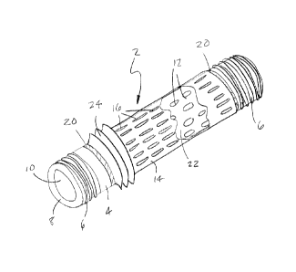
Referring to Figures 1 and 2, there is shown a preferred embodiment of a
wellbore
assembly 2 according to the present invention. There is a tubular member 4
adapted to be
connected to other tubular members by threaded ends 6. The tubular member
comprises a
base pipe having a side wall 8 defining a hollow interior 10 with an array of
openings 12
through the sidewall 8 to permit material into the interior. When connected
end to end via
threaded connections, the pipes co-operate to define a wellbore adapted to
receive and
transport fluids from an adjacent underground reservoir. It will be
appreciated that other
connection schemes for joining together the ends of base pipes are possible.
Openings 12
may be relatively large orifices through the side wall of the pipe, and are
distributed along a
prescribed length of the pipe. The size of openings 12 may be such that, in
and of
themselves, they do not impede the flow of solids that may be produced with
the liquids
entering the interior of the pipe. Also, the size and distribution of openings
12 does not so
subtract from the substance of the pipe material as to compromise the
structural strength of
the base pipe to the detriment of its performance.
Means for screening material, preferably in the form of a screening element
14,
extends about the base pipe over the array of openings 12 to control the
material that
reaches the array of openings. Screening element 14 is wrapped or mounted over
the base
CA 02752022 2011-09-09
- 6 -
pipe to act as a solids control device. In the illustrated embodiment,
screening element 14
is equivalent to a precisely punched screen (PPS) and is formed into an outer
sleeve
mounted substantially co-axially about the base pipe and is formed with
critically sized
apertures 16 for solids control. Alternatively, the means for screening
material may be a
wire-wrapped screen (WWS).
In a preferred arrangement, the outer sleeve configuration of screening
element 14
is mounted to the base pipe by means of welding 20 at opposite ends of the
screening
element so that material is limited to entering the annular space 22 between
the screening
element and side wall 8 of the base pipe through apertures 16.
Tubular member 4 in the form of the base pipe provides both structural support
for
the screening element 14, and, via large openings 12, a means of conveying
material
filtered by screening element 14 into the interior 10 of the pipe.
Wellbore assembly 2 also includes means for permitting relative movement
between the tubular member and the screening element 14 in order to lessen the
stresses
and strains on the screening element and to minimize deformation of the
apertures 16 in
screening element 14. In the illustrated embodiment, the means for permitting
relative
movement comprises a bellows structure 24 formed within the screening element
14.
Preferably, bellows structure 24 comprises a plurality of corrugations formed
in the actual
screening element 14. While bellows structure 24 is shown with angular
corrugations of
generally triangular cross-section in Figures 1 and 2, it is contemplated that
other
configurations such as corrugations having a rounded cross-section can also be
used. As
shown, bellows structure 24 is desirably formed at one end of the sleeve
member adjacent a
weld 20 to provide the maximum possible area on the remainder of the screening
element
for apertures 16. It will be understood by a skilled person that the bellows
structure is not
limited to this position as long as it is associated with the screening
element in a manner
that permits relative movement between the screening element 14 and the base
pipe.
CA 02752022 2011-09-09
- 7 -
Furthermore, it is contemplated that multiple means for permitting movement
between the
tubular member and the screening element in the form of multiple bellows
structures may
be formed in the screening element.
When a well containing a wellbore assembly as illustrated is subjected to high
temperatures, such as those associated with a thermal recovery operation, the
resulting
thermal stresses tend to induce strains on the assembly including the
screening element 14.
In the prior art, these strains could deform the apertures in the screening
element, at least
some of which apertures would experience enlargement at localized sites. As a
consequence, the screening element no longer retained the proper aperture size
originally
designed for solids control. This, in turn, led to, or contributed to, the
failure of the
screening element as a means of solids control, with the result that unwanted
solids, which
might damage downhole production equipment or otherwise impede or burden
production
operations, passed through the distorted apertures and through the larger
openings in the
base pipe, and thus entered the wellbore.
With respect to the arrangement of the present invention, the means for
permitting
relative movement between the screening element and the base pipe allows for
relieve of
stresses and accommodates strains that might otherwise build up in the
screening element.
For example, in the case of the present wellbore assembly being used in a
vertical well,
where the weight of the string of pipe is important, one end of the means for
permitting
relative movement is anchored by welding or the like to the base pipe. The
other end is
mounted to the outer screening element, which is the lighter than the base
pipe. The
screening element associated with a particular base pipe is not attached to
any other
screening element or base pipe. Thus, the means for permitting relative
movement is
required to moderate the stresses associated with only a single unit of pipe,
and to bear the
weight burden of only a single screening element and does not bear the burden
of an
accumulated weight of tubulars. In other words, in the present arrangement
when used in a
vertical well, the load bearing function is carried out by the body of the
base pipe, and by
CA 02752022 2011-09-09
¨ 8 ¨
the coupling points between joints of said base pipe, such as their threaded
connections 6.
The screening element 14 which is mounted about an individual unit of base
pipe, in
contrast, is not rigidly linked to the cumulative load associated with the
base pipe. As
stresses are imposed, for example due to thermal variations, the base pipe and
outer sleeve
element experience strains to varying degrees due to expansion or contraction
with respect
to each other. The means for permitting relative movement relieves stresses
that might
otherwise occur by accommodating or absorbing those strains. Furthermore, the
means for
permitting relative movement accomplishes this while bearing none of the
burden
associated with the weight of the base pipe, and while bearing the weight of
the associated
screening element.
In the case of horizontal wells, the cumulative weight of base pipes is not an
issue
as it is in vertical wells. However, thermal operations will induce strains in
the base pipe
and the outer screening element 14 because of the opportunity for relative
movement, and
the arrangement of the present invention also accommodates these strains. For
example, in
a horizontal well which is being used in a thermal recovery process, such as
steam injection
in an oil sand, the borehole will typically collapse along much of its length
around the pipe
assembly during the early stages of operation. This is a reflection of the
uncemented nature
of the sand. This collapse will inhibit to varying degrees the relative
movement of base
pipe and the surrounding screening element 14. However, to the extent that
some relative
movement occurs, the resulting stresses can be mitigated by the means for
permitting
relative movement Typically, at least one means for permitting relative
movement is
associated with each base pipe.
In a horizontal well, the base pipe and the screening element may be lying
along the
bottom of the borehole. Thus, there may be areas of weighted contact between
them. Such
circumstances may inhibit the movement of the base pipe with respect to the
screening
element. To facilitate relative movement of the base pipe with respect to the
outer
screening element, separating means for maintaining a stand-off or gap between
the two
CA 02752022 2011-09-09
- 9 -
may be employed. In a particular embodiment directed to this circumstance
which is best
shown in Figure 3, separating means in the form or protrusions such as rings
30 or
longitudinal ribs 32, or combinations of both, may be positioned between
tubular member
4 and the screening element (not shown) to maintain a physical separation
between the two
parts. In Figure 3, rings 30 and ribs 32 are shown formed on the exterior of
tubular
member 4. It will be readily apparent that different numbers, dimensions and
arrangements
of protrusions can be used and attached to the exterior of the base pipe or to
the interior of
the screening element. The protrusions act as separators, or centralizers, in
providing a
degree of stand-off between the tubular member and the screening element. The
protrusions also assist differential movement between the tubular member and
the
screening element to facilitate stress relief by allowing sliding of the
screening element14
over the tubular element 4.
In summary, the above¨described wellbore assembly with its base pipe and co-
axially wrapped screening element with stress relief means, allow the wellbore
to retain its
functionality by avoiding deformation of the screening element and allowing it
to maintain
its solids control function in environments of high temperature and mechanical
stress.
While the base pipe and associated outer screening element constitute a
functional
unit, they are not a fixed structural unit by virtue of the stress relieving
means associated
with the screening element which permits relative movement between the base
pipe and
screening element.
Although the present invention has been described in some detail by way of
example for purposes of clarity and understanding, it will be apparent that
certain changes
and modifications may be practised within the scope of the appended claims.