Note: Descriptions are shown in the official language in which they were submitted.
CA 02756348 2011 09 22
WO 2010/117526
PCT/US2010/026457
SYSTEM AND METHOD FOR MONITORING AN
INTEGRATED SYSTEM
BACKGROUND
[0001] The invention relates generally to a control system, and more
particularly to a control system and method for monitoring an integrated
system and
predicting events leading to an expected state of the integrated system.
[0002] Soaring fuel prices and shrinking water resources together with
emerging global norms for conservation of water and energy are forcing
industries to
manage their power and water utilization more efficiently. Thus, industries
are
identifying ways to attain a significant reduction in fossil-fuel based power
consumption and fresh water intake. One promising technology that enables
significant reduction in power consumption and fresh water intake includes an
integrated system having a water purification unit and a power generation
unit. The
power generation unit utilizes waste from the water purification unit to
generate
electrical power, and the integrated system operates on the electrical power
generated
by the power generation unit. Moreover, after meeting the power requirements
of the
integrated system, excess power is used for some other application. An example
of
the integrated system is General Electric waste-to-value system that generates
electricity and process steam (heat) in a flexible manner while recovering
potable
high-quality water.
[0003] Typically, key units or components of a water purification system
include a digester and a membrane bioreactor, while a key unit of a power
generation
system is a reciprocating gas engine or the like. The water purification
system
releases biogas as a waste that is consumed by the reciprocating gas engine to
generate electrical power. Further, the key units of the water purification
system
operate in a coordinated and an interdependent fashion, hence any upsets or
variations
in any key unit affect functionality and performance of the rest of the key
units. The
wastewater feed stream to the digester, for example, may have significant
variations
in flowrates, influent chemical oxygen demand, total suspended solids, total
dissolved
CA 02756348 2011 09 22
WO 2010/117526
PCT/US2010/026457
solids, temperature, nitrogen, phosphorous, sulphates and pH. The variations
in the
digester, in turn, impact operation of downstream process units, such as the
membrane
bioreactor. Moreover, performance variations in the water purification unit
may
result in significant variations in flowrate, composition and heating value of
the
biogas resulting in tripping of the gas engine, ultimately resulting in upset
and
shutdown of the integrated system.
[0004] Conventionally, the variations in the key units are monitored by
laboratory tests. Unfortunately, these lab tests are time consuming and are
not
sufficient for stopping frequent upsets of the integrated system leading to
large dead
time enclosed loop responses. Also, the operator of the integrated system is
unable to
detect any anomalous behavior of the integrated system until it is too late,
thereby
causing costly shutdowns and maintenance. Thus, due to absence of a realtime
or
near realtime monitoring process, the significant variations in the input feed
cannot be
monitored leading to expensive shutdowns of the integrated system.
[0005] It is therefore desirable to achieve robust and stable operation
of the
overall integrated system over long continuous periods of operation in the
presence of
wide-ranging variations. Further, it is desirable to have a realtime
monitoring and
control system configured to predict significant variations and disturbances
in the
integrated system well in advance, and take subsequent corrective actions to
prevent
the integrated system from stress leading to shutdowns.
BRIEF DESCRIPTION
100061 Briefly in accordance with one aspect of the technique a control
system
is provided. The control system includes an estimator configured to determine
a
present state of a device and compare the present state of the device with an
expected
state of the device. The control system also includes a predictor operatively
coupled
to the estimator, and configured to predict an event for execution by the
device to
reach the expected state of the device. The control system further includes a
supervisory control unit operatively coupled to the predictor and the device,
and
configured to facilitate execution of the predicted event by the device.
2
CA 02756348 2011 09 22
WO 2010/117526
PCT/US2010/026457
[0007] In accordance with a further aspect of the present technique, a
method
for monitoring and controlling a device is provided. The method includes
determining a present state of a device utilizing system parameters, comparing
the
present state of the device with an expected state of the device to determine
a
difference between the present state of the device and the expected state of
the device,
predicting an event utilizing the difference between the present state of the
device and
the expected state of the device to reach the expected state of the device,
and
executing the predicted event to reach the expected state of the device.
[0008] In accordance with a further aspect of the present technique, a
method
for monitoring and controlling a device is provided. The method includes
determining a realtime chemical oxygen demand of a feed stream of the device
using
a realtime total organic carbon and color of the feed stream, determining
realtime
parameters of the feed stream of the device, determining system parameters by
applying one or more estimation techniques to the realtime parameters,
predetermined
parameters, offline parameters and the realtime chemical oxygen demand,
determining a present state of the device utilizing the system parameters,
comparing
the present state of the device with an expected state of the device to
determine a
difference between the present state of the device and the expected state of
the device,
and predicting an event utilizing the difference between the present state of
the device
and the expected state of the device to reach the expected state of the
device.
[0009] In accordance with a further aspect of the present technique, a
control
system for monitoring and controlling a digester is provided. The system
comprises
an estimator configured to determine a present state of the digester. The
estimator is
further configured to compare the present state of the digester with an
expected state
of the digester. The system further includes a predictor operatively coupled
to the
estimator that is configured to predict an event for execution by the digester
to reach
the expected state of the digester. The system further includes a supervisory
control
unit operatively coupled to the predictor and the digester, and configured to
facilitate
execution of the predicted event by the digester.
3
CA 02756348 2011 09 22
WO 2010/117526
PCT/US2010/026457
[0010] In accordance with a further aspect of the present technique, a
system
is provided. The system includes a water purification system and a control
system.
The water purification system includes a digester configured to extract
substantial
amounts of chemical oxygen demand from impure wastewater to generate chemical
oxygen demand cleared water, one or more sensing devices operatively
associated
with the digester, and configured to sense realtime total organic carbon and
realtime
parameters of a feed stream of the digester. The water purification system
further
includes a membrane bioreactor operatively associated with the digester, and
configured to generate an effluent by removal of substantial amounts of
suspended
impurities and any remaining chemical oxygen demand from the chemical oxygen
demand cleared water. The water purification unit further includes a reverse
osmosis
unit operatively associated with the membrane bioreactor, and configured to
remove
soluble organics and total dissolved solids from the effluent. The control
system is in
operative association with the water purification system, and includes an
estimator
configured to determine a present state of the water purification system
utilizing the
realtime total organic carbon and the realtime parameters. The estimator is
further
configured to compare the present state of the water purification system with
an
expected state of the water purification system. The control system further
includes a
predictor operatively associated with the estimator, and configured to predict
an event
for execution by the water purification system to reach the expected state of
the water
purification system. The water purification system further includes a
supervisory
control unit operatively coupled to the predictor and the water purification
system,
and is configured to facilitate execution of the predicted event by the water
purification system.
DRAWINGS
[0011] These and other features, aspects, and advantages of the present
invention will become better understood when the following detailed
description is
read with reference to the accompanying drawings in which like characters
represent
like parts throughout the drawings, wherein:
4
CA 02756348 2011 09 22
WO 2010/117526
PCT/US2010/026457
[0012] FIG. 1 is a diagrammatical view of an exemplary system for
monitoring and controlling an integrated system, in accordance with aspects of
the
present technique;
[0013] FIG. 2 is a diagrammatical view illustrating an exemplary control
system for use with a device, in accordance with aspects of the present
technique;
[0014] FIG. 3 is a control diagram for monitoring and controlling the
integrated system of FIG. 1, in accordance with aspects of the present
technique;
[0015] FIG. 4 is a flow chart illustrating an exemplary method for
monitoring
and controlling the device, in accordance with aspects of the present
technique;
[0016] FIG. 5 is a flow chart illustrating an exemplary method of
programming a soft sensor by building a chemical oxygen demand (COD) model, in
accordance with aspects of the present technique;
[0017] FIG. 6 is a flow chart illustrating a method for determining a
present
state of a device utilizing system parameters, in accordance with aspects of
the present
technique; and
[0018] FIG. 7 is a flowchart illustrating a method for determining need
for a
corrective action, in accordance with aspects of the present technique.
DETAILED DESCRIPTION
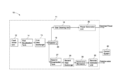
[0019] FIG. 1 is a diagrammatical view of an exemplary system 10 for
monitoring and controlling an integrated system 11, in accordance with aspects
of the
present technique. As illustrated in FIG. 1, the integrated system 11 includes
a water
purification system with capabilities of recovering purified water and
valuable energy.
In accordance with aspects of the present technique, the water purification
system 11
may include components, such as, a feed water unit 12, a first equalization
tank 14, a
first heat exchanger 15, a digester 16, a second equalization tank 27, a
second heat
exchanger 28, a membrane bioreactor 30, a reverse osmosis unit 32, a gas
cleaning
unit 18 and a power generation unit 22, or combinations thereof. Although the
CA 02756348 2011 09 22
WO 2010/117526
PCT/US2010/026457
present technique is described with reference to the water purification
system, it may
have application in other systems.
[0020] In accordance with further aspects of the present technique, the
system
may also include a control system 40 configured to monitor and control the
integrated system 11. As illustrated in FIG. 1, the control system 40 is
operatively
associated with the integrated system 11. The monitoring and control of the
integrated system 11 via the control system 40 enables continuous and
consistent
optimal operation of the integrated system 11.
[0021] Furthermore, the feed water unit 12 is in operative association
with the
first equalization tank 14. As shown in FIG. 1, the first equalization tank 14
is in
operative association with the first heat exchanger 15 and the digester 16 is
operatively coupled to the first heat exchanger 15. The feed water unit 12
intakes
impure wastewater, and transfers the impure wastewater to the first
equalization tank
14. The first equalization tank 14 may be configured to absorb variations in
the
amounts of impure wastewater. The impure wastewater from the first
equalization
tank 14 may then be transferred to the first heat exchanger 15. In one
embodiment,
the first heat exchanger 15 regulates temperature of the impure wastewater to
a
predetermined temperature for an optimized working of the digester 16. It may
be
noted that the first heat exchanger 15 may include a shell and tube heat
exchanger, a
regenerative heat exchanger, an adiabatic wheel heat exchanger, a plate fin
heat
exchanger, a fluid heat exchanger, a dynamic scraped surface heat exchanger, a
phase-
change heat exchanger, a multi-phase heat exchanger, or a spiral heat
exchanger, for
example.
[0022] Moreover, subsequent to the impure wastewater temperature
regulation
in the first heat exchanger 15 the impure wastewater is transferred to the
digester 16.
In one embodiment, the digester 16 may include an anaerobic digester. In an
alternative embodiment, the digester 16 may include an aerobic digester.
[0023] In addition, as depicted in FIG. 1, the digester 16 may include a
sensing device 20 for sensing a total organic carbon (TOC) and realtime
parameters of
6
CA 02756348 2011 09 22
WO 2010/117526
PCT/US2010/026457
the impure wastewater received from the first heat exchanger 15. In the
presently
contemplated embodiment, the digester 16 is shown as including the sensing
device
20. However, in other embodiments, the sensing device 20 may be incorporated
in
one or more of the components of FIG. 1. In certain embodiments, the sensing
device
20 may include a gas flow meter, a calorimeter, one or more hard sensors, and
one or
more soft sensors. As used herein, the term "realtime parameters" may include
parameters associated with the water and determined in realtime. Further, as
used
herein, the term "parameters" refers to measurable quantities and/or
properties of the
water that define purity of water. The realtime parameters, for example,
including
others may include pH, TOC, bacterial concentration, microbial concentration,
substrate concentration, temperature, biogas composition, alkalinity,
hardness, amount
of chlorides and phosphates, realtime color of feed stream, density of feed
stream, and
biogas quantity.
[0024] In one embodiment, the digester 16 may extract substantial amounts
of
chemical oxygen demand (COD) from the impure wastewater received from the
first
heat exchanger 15. Following the extraction of COD from the impure wastewater,
the
digester 16 generates a COD cleared water and releases biogas. Subsequently,
the
biogas is transferred to the gas cleaning unit 18 that cleans the biogas of
impurities
resulting in a purified biogas. The impurities, for example, may include gases
other
than biogas, such as H25. The gas cleaning unit 18 then transfers the purified
biogas
to the power generation unit 22 that generates electrical power utilizing the
purified
biogas. In certain embodiments, the power generation unit 22 may include a
reciprocating gas engine. In yet another embodiment, the power generation unit
22
may include a GE Jenbacher engine. Further, the electrical power generated by
the
power generation unit 22 may be utilized for operation of the integrated
system 11.
Also, in other embodiments, the electrical power may be utilized for operation
of
other industrial plants.
[0025] Subsequent to the generation of the COD cleared water, variations
in
amount of the COD cleared water may be absorbed by the second equalization
tank
27. In one embodiment, the second equalization tank 27 may include a total
suspended solids (TSS) removal system (not shown). In still another
embodiment, the
7
CA 02756348 2011 09 22
WO 2010/117526
PCT/US2010/026457
TSS removal system may include entrapped air floatation system (EAF),
dissolved air
floatation system (DAF), belt press, screw press, or similar devices.
[0026] Furthermore, temperature of the COD cleared water may be regulated
in the second heat exchanger 28. Consequent to the regulation of temperature
of the
COD cleared water, a temperature regulated COD cleared water may be generated.
The second heat exchanger 28, for example, may include a shell and tube heat
exchanger, a regenerative heat exchanger, an adiabatic wheel heat exchanger, a
plate
fin heat exchanger, a fluid heat exchanger, a dynamic scraped surface heat
exchanger,
a phase-change heat exchanger, a multi-phase heat exchanger, or a spiral heat
exchanger.
[0027] In addition, the temperature regulated COD cleared water is
transferred
to the membrane bioreactor 30 that is in operative association with the second
heat
exchanger 28. The membrane bioreactor 30 facilitates removal of any remaining
COD from the temperature regulated COD cleared water received from the second
heat exchanger 28. The membrane bioreactor 30 also facilitates removal of
substantial amounts of suspended impurities from the temperature regulated COD
cleared water. Consequent to the removal of the remaining COD and suspended
solids by the membrane bioreactor 30, an effluent is produced.
[0028] Further, the effluent is transferred to the reverse osmosis unit
32 that is
in an operative association with the membrane bioreactor 30. The reverse
osmosis
unit 32 removes soluble organics and total dissolved solids (TDS) from the
effluent.
Consequent to the removal of the soluble organics and the TDS from the
effluent,
potable water is generated.
[0029] FIG. 2 is a diaganunatical view illustrating one embodiment of the
exemplary control system 40 for use with a device, in accordance with aspects
of the
present technique. As illustrated with reference to FIG. 1, the control system
40 may
be configured to monitor and control the device for optimized and efficient
working
of the device. In one embodiment, the device may include the integrated system
11
(see FIG. 1). However, in other embodiments, the device may include the
digester 16
8
CA 02756348 2011 09 22
WO 2010/117526
PCT/US2010/026457
(see FIG. I), the membrane bioreactor 30 (see FIG. I), the first equalization
tank 14
(see FIG. I), the first heat exchanger 15 (see FIG. 1), the second
equalization tank 27
(see FIG. I), the second heat exchanger 28 (see FIG. I), the power generation
unit 22
(see FIG. 1), or combinations thereof.
[0030] In accordance with a presently contemplated configuration, the
control
system 40 may include a supervisory control unit 24 and a control model 26.
Furthermore, as depicted in FIG. 2, the control model 26 may include a
chemical
oxygen demand soft sensor 42, an estimator 44, a predictor 46 and an event
detector
48.
[0031] The COD soft sensor 42 is in operational communication with the
estimator 44. The COD soft sensor 42 may be configured to determine a realtime
COD corresponding to a realtime total organic carbon (TOC) of a feed stream to
the
device. In one embodiment, the realtime TOC may be determined by the sensing
device 20 (see FIG. I). Furthermore, the COD soft sensor 42 may be configured
to
determine the realtime COD utilizing a COD model.
[0032] In accordance with aspects of the present technique, the COD model
may be built by mapping offline TOCs and color of the feed stream to
corresponding
offline CODs to determine a relationship between the offline TOCs and the
realtime
color of the feed stream and the corresponding offline CODs. In one
embodiment, the
offline CODs and the offline TOCs may be determined by using COD laboratory
tests
and TOC laboratory tests, respectively. In ceratin embodiments, the color of
the feed
stream may be determined by the sensing device 20 (see FIG. I). The sensing
device
20 for determining the color of the feed stream, for example, may include the
calorimeter. Also, in one embodiment, the relationship between the offline
TOCs and
the color of the feed stream to the corresponding offline CODs is determined
by using
artificial intelligence.
[0033] In addition, the estimator 44 of the control model 26 may be
configured to determine system parameters utilizing the realtime parameters,
the
realtime COD, offline parameters and predetermined parameters. The system
9
CA 02756348 2011 09 22
WO 2010/117526
PCT/US2010/026457
parameters, for example, may include bacterial concentration, substrate
concentration,
microbial concentration, device COD, volatile fatty acids concentration,
alkalinity,
device TOC, hardness, ammonia concentration, phosphates concentrations,
sulphates
concentrations, biogas composition, device pH, or combinations thereof. As
used
herein, the term "predetermined parameters" may be used to refer to parameters
associated with the feed stream of the device while the device operates in a
steady
state condition. More particularly, the term "predetermined parameters" may be
used
to refer to the parameters of the feed stream of the device when the device
operates in
an optimized condition. In other words, the term "predetermined parameters"
may be
representative of steady state parameters of the device. Further, as used
herein, the
term "offline parameters" may be representative of the parameters that are
determined
offline. Also, the offline parameters may be determined by utilizing
laboratory tests.
The offline parameters, for example, may include pH, the TOC, the COD,
bacterial
concentration (MLSS), substrate concentration, microbial concentration,
nitrogen,
phosphates concentration, sulphates concentration, temperature, biogas
composition,
alkalinity, hardness, amount of chlorides and, biogas quantity.
[0034] With continuing reference to FIG. 2, the estimator 44 may be
further
configured to determine a present state of the device and compare the present
state of
the device with an expected state of the device. In one embodiment, the
estimator 44
determines the present state of the device using the system parameters. As
used
herein, the term "present state of the device" may be used to refer to an
operating
condition of the device. Further, the term "expected state of the device" may
be used
to refer to a steady state operating condition of the device while the device
operates in
an optimized condition. In other words, the term "expected state of the
device" may
be used to refer to a state of the device when the system parameters are
substantially
similar to the predetermined parameters.
[0035] Further, as illustrated in the presently contemplated embodiment,
the
predictor 46 is operatively coupled to the estimator 44, and is configured to
predict an
event to be executed by the device to enable the device to reach a subsequent
state of
the device. The predicted event may include changes, variations or adjustments
in
concentrations, for example, change in pH, change in biomass concentration,
change
CA 02756348 2011 09 22
WO 2010/117526
PCT/US2010/026457
in alkalinity, change in inorganic carbon, change in nitrogen and phosphorous
levels,
change in hydrogen concentration, or combinations thereof.
[0036] In addition, the event detector 48 is shown as being in operative
association with the predictor 46 and the supervisory control unit 24. In one
embodiment, the event detector 48 is configured to determine the subsequent
state of
the device after execution of the predicted event. In still another
embodiment, the
event detector 48 may be configured to determine a corrective action for the
device
when the subsequent state of the device is different from the expected state
of the
device. The corrective action, for example, may include change in input feed
rate,
change in COD concentration, change in temperature, change in redox potential,
change in nutrient addition, chemicals, addition, reseeding, and
bioaugmentation.
Consequent to the determination of the corrective action, the supervisory
control unit
24 corrects the estimator 44 and the predictor 46. In certain embodiments, the
supervisory control unit 24 corrects the predictor 46 and the estimator 44 by
changing
a state of the estimator 44 and the predictor 46. In one embodiment, the state
of the
predictor 46 and the estimator 44 may be changed by determining the offline
parameters, and updating the predictor 44 and the estimator 46 utilizing the
offline
parameters.
[0037] Turning now to FIG. 3, a control diagram 60 for monitoring and
controlling an integrated system, such as, the integrated system 11 of FIG. 1,
is
illustrated. In a presently contemplated embodiment, reference numeral 62 is
representative of feed. In certain embodiments, the feed 62 is similar to the
realtime
parameters. Further, reference numeral 64 is representative of a set point. In
one
embodiment, the set point 64 may be representative of the predetermined
parameters.
Moreover, a first logic 66 receives as input feedback controls 78, the set
point 64, feed
forward controls 68, and the feed 62 to determine optimizing controls. The
optimizing controls may be implemented by the supervisory control unit 24 on
the
integrated system 11 to enable optimized working of the integrated system 11.
[0038] Further, as illustrated in FIG. 3, the event detector 48 is in
operational
communication with the integrated system 11. The event detector 48 may
determine
11
CA 02756348 2011 09 22
WO 2010/117526
PCT/US2010/026457
the subsequent state of the integrated system 11 after implementation of the
optimizing controls. In one embodiment, the subsequent state of the integrated
system 11 may be representative of the feedback controls 78. In other words,
the
feedback controls 78 may include subsequent state controls that define the
subsequent
state of the integrated system 11 that is achieved after implementation of the
optimizing controls by the supervisory control unit 24 on the integrated
system 11. In
certain embodiments, the optimizing controls may be representative of the
predicted
event. In still another embodiment, the corrective action may be
representative of the
feedback controls 78.
[0039] With continuing reference to FIG. 3, a second logic 72 may be
configured to receive the feed forward controls 68 and the set point 64. The
second
logic 72 transfers the feed forward controls 68 and the set point 64 to the
control
model 26. Subsequently, an offline analysis may be conducted by an offline
processor 70 to determine the offline parameters. As illustrated in FIG. 3,
the control
model 26 may determine the system parameters at step 74 and the present state
of the
integrated system 11 at step 76.
[0040] Furthermore, the predictor 46 utilizes the system parameters and
the
present state of the integrated system 11 for determination of the predicted
event. In
certain embodiments, the predicted event may be representative of the feed
forward
controls 68.
[0041] FIG. 4 is a flow chart 80 illustrating an exemplary method for
monitoring and controlling a device, such as integrated system 11 (see FIG.
1), in
accordance with aspects of the present technique. Reference numeral 82 may be
representative of the realtime TOC. The realtime TOC may be determined by
utilizing the sensing device 20 (see FIG. 1). The method starts at step 84,
where the
realtime parameters may be determined using the sensing device 20 (see FIG.
1).
Further, at step 86, the realtime COD may be determined corresponding to the
realtime TOC 82 and colors of the feed stream. As illustrated with reference
to FIG.
1, the colors of the feed stream may be one of the realtime parameters, and
thus, may
be determined by the sensing device 20 (see FIG. 1). The determination of the
12
CA 02756348 2011 09 22
WO 2010/117526
PCT/US2010/026457
realtime COD corresponding the realtime TOC and the colors of the feed stream
may
be better understood with reference to FIG. 5.
[0042] Turning now to FIG. 5, a flow chart 110 illustrating an exemplary
method of programming a soft sensor, such as the COD soft sensor 42 (see FIG.
2),
by building a chemical oxygen demand model, in accordance with aspects of the
present technique is depicted. Reference numeral 112 may be representative of
offline TOCs, while the colors of the feed stream may be represented by
reference
numeral 113. Further, reference numeral 114 may be representative of
corresponding
offline CODs. The method starts at step 116, where the offline TOCs 112 and
the
colors of the feed stream 113 are mapped to the corresponding offline CODs.
Consequent to the mapping at step 116, a relationship between the offline TOCs
112
and the colors of the feed stream 113 to the corresponding offline CODs 114 is
established. In one embodiment, the relationship may be determined using
artificial
intelligence on the offline TOCs 112 and the colors of the feed stream 113 and
the
corresponding offline CODs 114.
[0043] With continuing reference to FIG. 5, the relationship between the
offline TOCs 112 and the colors of the feed stream 113 and the corresponding
offline
CODs 114 is used to build a COD model as indicated by step 118. As used
herein,
the term "COD model" may be used to refer to a model capable of determining a
realtime COD corresponding the realtime TOC.
[0044] Subsequent to the building of the COD model, the COD soft sensor
42
may be programmed utilizing the COD model, as depicted in step 120. The COD
soft
sensor 42 may be used to determine the realtime CODs corresponding to the
realtime
TOCs and the colors of the feed stream. In one embodiment, the realtime TOCs
may
be determined by the sensing device 20 (see FIG. 1). As previously noted with
reference to FIG. 1, the color of the feed stream may be determined by the
calorimeter.
[0045] With returning reference to FIG. 4, at step 88, a present state of
the
device is determined. As previously noted with reference to FIG. 2, the
estimator 44
13
CA 02756348 2011 09 22
WO 2010/117526
PCT/US2010/026457
determines the present state of the device. The determination of the present
state of
the device may be better understood with reference to FIG. 6.
[0046] Referring now to FIG. 6, a flow chart 130 illustrating a method
for
determining a present state of a device utilizing system parameters, in
accordance
with aspects of the present technique, is depicted. Reference numeral 132 may
be
representative of realtime parameters, while reference numeral 94 may be
representative of predetermined parameters (see FIG. 4). Also, reference
numeral 138
may be representative of offline parameters, while reference numeral 134 may
be
representative of realtime COD 134. The method starts at step 140, where
system
parameters may be determined utilizing the realtime parameters 132, the
offline
parameters 138, the predetermined parameters 94, and the realtime COD 134. As
previously noted with reference to FIG. 2, the system parameters may be
determined
by the estimator 44. The system parameters may generally be represented by
reference numeral 142.
[0047] In certain embodiments, the estimator 44 may determine the system
parameters 142 by application of mathematical formulas. In accordance with
exemplary aspects of the present technique, equations (1) to (3) represent
determination of the system parameters 142 by application of formulas.
[0048] In one embodiment, when the feed stream concentration and the
bacterial concentration of an acidogenic phase is represented by X1 and X2
respectively, the microbial concentration and the substrate concentration of a
methanogenic phase is represented by X3 and X4 respectively, the alkalinity,
inorganic
carbon and ammonia concentrations are represented by X5, X7 and X8
respectively,
then a change in concentrations of X1, X2, X3, X4, X5, X7 and X8 may be
represented
by control affine equation (1) as:
= f ( X ) + g( X ).0 (1)
14
CA 02756348 2011 09 22
WO 2010/117526
PCT/US2010/026457
where X is a change in concentrations vector and X may be represented by
X = [X I, X2, X3, X4, X5, X6, X7 . Also, in equation (1) u may be determined
by
utilizing equation (2) as follows:
u =[D, X ,T , iõ, X8,in (2)
where u is a vector of all the parameters that affect the device, D is the
dilution rate,
which is a ratio of the feed stream flowrate to the volume of the device, and
T is the
temperature of the device. Further, in equation (2) subscript in is indicative
of
realtime parameters, offline parameters and/or predetermined parameters of the
feed
stream.
[0049] Further, the system parameters 142 may be determined by equation
(3)
as follows:
Y = f (X) (3)
where Y may be representative of the system parameters. Further, if the
predetermined parameters 94 are represented by 2, then drift in prediction of
the
event may be determined as a difference of Y and 2.
[0050] Consequent to the determination of the system parameters 142, the
present state of the device may be determined at step 144. As previously noted
with
reference to FIG. 2, the present state of the device may be determined by the
estimator
44.
[0051] With returning reference to FIG. 4, at step 90, the present state
of the
device determined at step 88 is compared with the expected state of the
device.
Further, the comparison of the present state of the device with the expected
state of
the device enables determination of a difference between the present state of
the
device and the expected state of the device. In one embodiment, the expected
state of
the device may be determined by determining the predetermined parameters 94
(see
FIG. 6).
CA 02756348 2011 09 22
WO 2010/117526
PCT/US2010/026457
[0052] Consequent to the determination of the difference between the
present
state of the device and the expected state of the device, an event is
predicted at step
96, where the predicted event may enable the device to reach the expected
state. As
illustrated with reference to FIG. 2, the event is predicted by the predictor
46. In one
embodiment, the predictor 46 predicts the event such that implementation of
the
predicted event enables optimized working of the device. More particularly,
the
implementation of the predicted event enables the device to reach the expected
state
of the device. The predicted event, for example, may include heating or
cooling of an
input feed, addition of chemicals, increase or decrease in acidogenic
bacterial
concentration, increase or decrease in methanogenic bacterial concentration,
increase
or decrease in bacterial activity, fixing one or more components of the
device,
increase or decrease in oxygen content of the input feed, or combinations
thereof, as
previously noted.
[0053] In one embodiment, the device may be controlled to implement the
predicted event as indicated by step 98. As previously noted with reference to
FIG. 2,
the supervisory control unit 24 controls the device to implement the predicted
event.
More particularly, the supervisory control unit 24 may be configured to
control the
device to implement the predicted event to enable the device reach the
expected state.
[0054] Further, at step 100, an impact of the implementation of the
predicted
event is determined. In one embodiment, the impact of the predicted event is
determined by determining the subsequent state (see FIG. 2) of the device
after
implementation of the predicted event. As illustrated with reference to FIG.
2, the
event detector 48 (see FIG. 2) determines the subsequent state of the device.
[0055] Consequent to the determination of the impact of the
implementation
of the predicted event, corrective action to minimize any error in the
prediction of the
event may be determined at step 102. Further, as previously noted with
reference to
FIG. 2, the event detector 48 may be configured to determine the corrective
action. In
one embodiment, the corrective action may be determined when there is a need
for
corrective action. Determination of the need of the corrective action may be
better
understood with reference to FIG. 7.
16
CA 02756348 2011 09 22
WO 2010/117526
PCT/US2010/026457
[0056] FIG. 7 is a flowchart 150 illustrating a method for determining a
need
for a corrective action, in accordance with aspects of the present technique.
Reference numeral 152 is representative of a predicted event. By way of
example,
reference numeral 152 may be representative of the predicted event generated
at step
96 (see FIG. 4). The method starts at step 154 where a subsequent state of the
device
is determined. Further to the determination of the subsequent state, a check
may be
carried out at step 156 to determine whether the subsequent state of the
device is
similar to the expected state of the device. At step 156, if it is verified
that the
subsequent state of the device is substantially similar to the expected state
of the
device, then it may be concluded that no corrective action is necessary as
indicated by
reference numeral 160. However, at step 156, if it is verified that the
subsequent state
of the device is different from the expected state of the device, then it may
be
concluded that corrective action may be desired, as indicated by the reference
numeral
158. As previously noted with reference to FIG. 2, the event detector 48 may
be
configured to determine the corrective action.
[0057] With returning reference to FIG. 4, consequent to processing by
step
102, if it is determined that corrective action is desired then the corrective
action may
be implemented to minimize any error in the prediction of the event, as
depicted by
step 104. As previously noted, the corrective action is implemented by the
supervisory control unit 24 (see FIG. 2) to minimize an error in the
prediction of the
event. In one embodiment, the supervisory control unit 24 implements the
corrective
action on the estimator 44 (see FIG. 2) and the predictor 46 (see FIG. 2),
when there
is a need for the corrective action.
[0058] By applying the described technique hereinabove, significant
variations and disturbances in a device may be determined well in advance, and
subsequent actions may be taken to prevent the system from stress. Thus, the
present
technique provides a realtime monitoring and controlling system for optimized
working of the system and prevents the system from shutdowns. Further, the
illustrated technique improves reliability of the device and reduces number of
shutdowns of the device.
17
CA 02756348 2016-07-27
233498
[0059] While only
certain features of the invention have been illustrated and
described herein, many modifications and changes will occur to those skilled
in the
art. It is, therefore, to be understood that the appended claims are intended
to cover
all such modifications and changes as fall within the scope of the invention
described.
=
=
18