Note: Descriptions are shown in the official language in which they were submitted.
CA 02767596 2015-03-18
APPARATUS FOR CLOSURE OF A LUMEN AND METHODS OF USING THE
SAME
FIELD OF THE APPLICATION
The present invention relates generally to minimally-invasive surgical
apparatus
and methods, and specifically to minimally-invasive apparatus and techniques
for
puncture site management.
BACKGROUND OF THE APPLICATION
Many vascular procedures are performed using minimally invasive techniques,
often by accessing the femoral artery or another major blood vessel through a
puncture
opening made in the blood vessel, and accessing a surgical site via the blood
vessel.
Upon completion of the procedure, the puncture opening must be closed. The
goal of
repair of the puncture opening is to create hemostasis in tissue of the tissue
tract leading to
the blood vessel wall, and to allow the puncture opening to seal. Sealing the
puncture
opening allows blood to eventually flow again through the blood vessel without
thrombosis or embolism, and allows the tissue in the tissue tract leading to
the vessel to
heal.
The earliest technique for closing a puncture opening was the simple
application
of direct physical pressure, either by a medical professional, and/or by a
simple clamp. A
drawback of direct pressure is that is it often painful for the patient, and
requires extended
immobilization of the patient and attention of the medical professional.
As an alternative to direct pressure, various devices for wound closure at a
vascular puncture site have been developed, including biodegradable plugs,
sutures,
staples, ultrasound, collagen, collagen with thrombin, collagen with an
anchor, and
hemostatic patches and pads. Typically, these devices and technique are
generally
effective for closing punctures having that arc suitable for delivery of up to
16 French
CA 02767596 2012-01-09
WO 2011/004374 PCT/1L2010/000549
endovascular systems.
Commercial alternatives to direct pressure include:
= Angio-SealTM Vascular Closure Device (St. Jude Medical, Inc., St. Paul,
MN)
= PercloseTM (Abbott Laboratories, Abbott Park, IL)
= VasoSealTM (Datascope, Montvale, NJ)
= DuettTM (Vascular Solutions, Minneapolis, MN)
= HeartStitch (Sutura, Fountain Valley, CA)
= Syveke hemostasis products (Marine Polymer Technologies, Inc., Danvers,
MA)
US Patent 6,743,195 to Zucker describes apparatus for hemostasis of an artery
having a puncture after arterial catheterization. The apparatus includes a
catheter
introducer having a forward end, and a hemostasis device including an elongate
flexible
hollow shaft having an inflatable anchor balloon at a forward end thereof, and
an
inflatable peripheral balloon adjacent the forward end of the flexible hollow
shaft. The
hemostasis device is arranged to be insertable into an artery via the catheter
introducer.
US Patent 7,731,732 to Ken describes a closure device for closing a puncture
wound having a distal section that can be placed against the interior wall of
a vessel, and a
proximal section that bunches in the tissue tract to close the wound. One
variation of the
device provides for removing the distal section from the vessel so that it
resides also in the
tissue tract after the proximal section has been securely bunched and lodged
within the
tissue tract in order to provide unobstructed fluid flow in the vessel.
The following patents may be of interest:
US Patent 5,527,322 to Klein et al.
US Patent 5,613,974 to Andreas et al.
US Patent 5,728,134 to Barak
US Patent 5,860,991 to Klein et al.
US Patent 5,921,994 to Andreas et al.
US Patent 6,117,145 to Wood et al.
US Patent 6,206,893 to Klein et al.
2
CA 02767596 2012-01-09
WO 2011/004374 PCT/1L2010/000549
US Patent 6,846,321 to Zucker
US Patent 7,008,441 to Zucker
US Patent 7,115,127 to Lindenbaum et al.
US Patent 7,223,266 to Lindenbaum et al.
US Patent 7,662,168 to McGuckin, Jr. et al.
US Patent 7,662,161 to Briganti et al.
US Patent Application Publication 2006/0167476 to Burdulis, Jr. et al.
SUMMARY OF APPLICATIONS
In some applications of the present invention, a generally tubular
endovascular
prosthesis provides hemostasis to a puncture site in a body lumen, such as of
blood vessel.
The prosthesis comprises structural stent elements, and includes first and
second structural
portions, which meet each other at a juncture. The prosthesis is initially
folded at the
juncture, such that second structural portion is folded within the first
structural portion.
The prosthesis is introduced into the lumen via the puncture while in this
folded state, and
positioned several centimeters from the puncture site. The prosthesis is
unfolded in the
lumen, such that a portion of the second structural portion extends alongside
the puncture
site, thereby at least partially covering and blocking blood flow to the
puncture site. For
some applications, the prosthesis further comprises a blood-impervious fluid
flow guide,
which at least partially covers the second structural portion.
The structural stent elements of the second structural portion provide at
least
partial tissue scaffolding to enable hemostasis at the puncture site, and
provide a surface
that stimulates blood coagulation. The stent elements also reduce blood flow
in the
vicinity of the puncture site, enabling quicker healing of the puncture site.
The first
structural portion helps hold the entire prosthesis in place by providing good
contact with
the lumen wall. The first structural portion also may impede blood penetration
into the
space between the second structural portion and the puncture site.
The curative features of the prosthesis described in the preceding paragraph
are
provided by the prosthesis even in configurations that do not include the
fluid flow guide,
particularly if the structural stent elements have a high density, realized,
for example, by a
tight braided structure. In configurations that include the fluid flow guide,
the fluid flow
3
CA 02767596 2012-01-09
WO 2011/004374 PCT/1L2010/000549
guide also helps seal the puncture site, and stimulates tissue growth and
coagulation.
There is therefore provided, in accordance with an application of the present
invention, apparatus including a generally tubular endovascular prosthesis,
which is
configured to transition between a radially-compressed state and a radially-
expanded
state, the prosthesis including:
a first structural portion, which has first and second ends, and which is
generally
cylindrical when the prosthesis assumes the radially-expanded state; and
a second structural portion, which has first and second ends, and which is
generally cylindrical when the prosthesis assumes the radially-expanded state,
wherein the first end of the first structural portion and the first end of the
second
structural portion meet each other at a juncture, and
wherein the prosthesis is configured to transition from (a) an initial folded
state, in
which the second structural portion is folded into the first structural
portion at the
juncture, such that the second end of the second structural portion axially
extends in a
direction from the juncture toward the second end of the first structural
portion, to (b) an
unfolded state, in which the second structural portion is no longer positioned
within the
first structural portion, and the second end of the first structural portion
and the second
end of the second structural portion are positioned at opposite ends of the
prosthesis.
For some applications, the prosthesis further includes a blood-impervious
fluid
flow guide, which at least partially covers the second structural portion.
Optionally, the
fluid flow guide is biodegradable, in which case the biodegradable polymer may
be
selected from the group consisting of: starch, gelatin, dextran, dextrin,
alginate,
hydroxypropyl methylcellulose, hydroxypropyl cellulose, polyvinyl alcohol,
poly(L-lactic
acid), poly(lactide-co-glycolide), polyethylene glycol, polycaprolactone,
polyphosphate
ester, poly(hydroxy-butyrate), poly(glycolic acid), poly(DL-lactic acid),
poly(amino acid),
chitosan, collagen and cellulose, polyethylenecarbo-nate, and a mixture
thereof.
For some applications, the second structural portion is shaped so as to define
an
elongated opening that extends axially along at least a portion of the second
structural
portion, when the prosthesis assumes the radially-expanded state. For some
applications,
an arc of the second structural portion circumscribed by the elongated opening
is
generally constant along an entire length of the elongated opening.
Alternatively, an arc
of the second structural portion circumscribed by the elongated opening may be
less at a
4
CA 02767596 2012-01-09
WO 2011/004374 PCT/1L2010/000549
first end of the elongated opening than at a second end of the elongated
opening, which
second end of the elongated opening is closer to the second end of the second
structural
portion than the first end of the elongated opening is to the second end of
the second
structural portion. Optionally, the arc may monotonically increase from the
first end of
the elongated opening to the second end of the elongated opening.
For some applications, the first end of the first structural portion is shaped
so as to
define a plurality of first loops, the first end of the second structural
portion is shaped so
as to define a plurality of second loops, and the first loops are
interconnected with the
second loops so as to define the juncture.
For some applications, an average diameter of the first structural portion is
greater
than an average diameter of the second structural portion, when the prosthesis
assumes the
radially-expanded and unfolded states. For some applications, a diameter of a
portion of
the first structural portion increases toward the second end thereof. For some
applications, a diameter of a portion of the second structural portion
increases toward the
second end thereof.
For some applications, the first structural portion is flared radially outward
at the
first end thereof, when the prosthesis assumes the radially-expanded and
unfolded states.
Alternatively or additionally, the second structural portion may be flared
radially outward
at the second end thereof, when the prosthesis assumes the radially-expanded
and
unfolded states.
For any of the applications described above, the apparatus may further include
a
first elongated member, which is initially in contact with the first
structural portion, and
the first elongated member and the prosthesis are arranged such that axial
motion of the
first elongated member with respect to the prosthesis results in radial
expansion of the
first structural portion. For some applications, the first elongated member
includes a first
generally tubular sheath, which is initially externally positioned surrounding
at least a
portion of the first structural portion, such that the first sheath initially
holds the prosthesis
in the radially-compressed state. Optionally, the first sheath may be slidable
with respect
to the first structural portion.
For some applications, the apparatus further includes a second elongated
member,
which is initially in contact with the second structural portion, and the
second elongated
member and the prosthesis are arranged such that axial motion of the second
elongated
5
CA 02767596 2012-01-09
WO 2011/004374 PCT/1L2010/000549
member with respect to the prosthesis transitions the prosthesis to the
unfolded state. For
some applications, the second elongated member and the prosthesis are arranged
such that
the axial motion of the second elongated member with respect to the prosthesis
transitions
the prosthesis to the unfolded state and results in radial expansion of the
second structural
portion. For some applications, the second elongated member is initially
positioned
between the second structural portion and a central longitudinal axis of the
prosthesis.
For some applications, the second elongated member and the second structural
portion are
configured such that the second elongated member is frictionally adherent to
the second
structural portion. For some applications, the second elongated member
includes a second
generally tubular sheath, which is shaped so as to define an internal lumen
sized to allow
passage therethrough of a guidewire.
For any of the applications mentioned above, the apparatus may further include
sterile packaging, in which the prosthesis is initially stored in the radially-
compressed and
initial folded states.
For any of the applications mentioned above, the first and second structural
portions may include a plurality of structural stent elements. For some
applications, the
structural stent elements include a super-elastic alloy. For some
applications, the
prosthesis is configured to be self-expandable. For some applications, the
super-elastic
alloy includes Nitinol. For some applications, the super-elastic alloy
includes a material
selected from the group consisting of: a braided super-elastic alloy, and a
woven super-
elastic alloy.
There is further provided, in accordance with an application of the present
invention, a method for providing hemostasis to a puncture site in a body
lumen, the
method including:
providing a generally tubular endovascular prosthesis, which includes first
and
second structural portions that meet each other at a juncture;
introducing the prosthesis into the lumen via the puncture site, while the
prosthesis
is in a radially-compressed state and an in an initial folded state, in which
the second
structural portion is folded into the first structural portion at the
juncture; and
while the prosthesis is within the lumen, transitioning the prosthesis (a)
from the
radially-compressed state to a radially-expanded state, and (b) from the
initial folded state
to an unfolded state, in which unfolded state the second structural portion is
no longer
6
CA 02767596 2012-01-09
WO 2011/004374 PCT/1L2010/000549
positioned within the first structural portion, such that a portion of the
second portion
extends alongside the puncture site.
For some applications, providing the prosthesis includes providing the
prosthesis
in which:
the first structural portion has first and second ends, and is generally
cylindrical
when the prosthesis assumes the radially-expanded state,
the second structural portion has first and second ends, and is generally
cylindrical
when the prosthesis assumes the radially-expanded state,
the second end of the second structural portion axially extends in a direction
from
the juncture toward the second end of the first structural portion, when the
prosthesis
assumes the initial folded state, and
the second end of the first structural portion and the second end of the
second
structural portion are positioned at opposite ends of the prosthesis, when the
prosthesis
assumes the unfolded state.
For some applications, providing the prosthesis includes providing the
prosthesis
in which the first end of the first structural portion is shaped so as to
define a plurality of
first loops, the first end of the second structural portion is shaped so as to
define a
plurality of second loops, and the first loops are interconnected with the
second loops so
as to define the juncture.
For some applications, transitioning the prosthesis from the radially-
compressed
state to a radially-expanded state includes radially expanding the first
structural portion by
axially moving a first elongated member that is initially in contact with the
first structural
portion. For some applications, the first elongated member includes a first
generally
tubular sheath, which is initially externally positioned surrounding at least
a portion of the
first structural portion, such that the first sheath initially holds the
prosthesis in the
radially-compressed state, and radially expanding the first structural portion
includes
removing the first sheath from the at least a portion of the first structural
portion. For
some applications, removing includes sliding the first sheath with respect to
the first
structural portion.
For some applications, transitioning the prosthesis from the initial folded
state to
the unfolded state includes axially moving a second elongated member that is
initially in
contact with the second structural portion. For some applications,
transitioning the
7
CA 02767596 2012-01-09
WO 2011/004374 PCT/1L2010/000549
prosthesis from the radially-compressed state to the radially-expanded state
includes
radially expanding the second structural portion by axially moving the second
elongated
member. For some applications, providing the prosthesis includes providing the
prosthesis such that the second elongated member is initially positioned
between the
second structural portion and a central longitudinal axis of the prosthesis.
For some
applications, the second elongated member includes a second generally tubular
sheath,
which is shaped so as to define an internal lumen, and introducing the
prosthesis includes
advancing a guidewire into lumen via the puncture site, and advancing the
prosthesis over
the guidewire that passes through the lumen.
For some applications, providing the prosthesis includes providing the
prosthesis
including a blood-impervious fluid flow guide, which at least partially covers
the second
structural portion.
For some applications, providing the prosthesis includes providing the
prosthesis
in which the second structural portion is shaped so as to define an elongated
opening that
extends axially along at least a portion of the second structural portion,
when the
prosthesis assumes the radially-expanded state.
For some applications, providing the prosthesis includes providing the
prosthesis
in which the first and second structural portions include structural stent
elements. For
some applications, providing the prosthesis includes providing the prosthesis
in which the
structural stent elements include a super-elastic alloy. For some
applications, providing
the prosthesis includes providing the prosthesis configured to be self-
expandable. For
some applications, providing the prosthesis includes providing the prosthesis
in which the
super-elastic alloy includes a material selected from the group consisting of:
a braided
super-elastic alloy, and a woven super-elastic alloy.
For some applications, introducing the prosthesis includes positioning the
prosthesis such that the juncture is at a distance from the puncture site of
between 0.5 and
3 cm. Alternatively or additionally, introducing the prosthesis may include
positioning
the prosthesis such that the juncture is at a distance from the puncture site
of between 0.1
and 1.5 times a diameter of the lumen at the puncture site.
The present invention will be more fully understood from the following
detailed
description of embodiments thereof, taken together with the drawings, in
which:
8
CA 02767596 2012-01-09
WO 2011/004374 PCT/1L2010/000549
BRIEF DESCRIPTION OF THE DRAWINGS
Figs. 1-3 are schematic illustrations of a generally tubular endovascular
prosthesis,
in accordance with respective applications of the present invention;
Figs. 4 and 5 are schematic cross-sectional and perspective illustrations,
respectively, of the prosthesis of Figs. 1-3 in an initial folded state, in
accordance with an
application of the present invention;
Figs. 6A-C are schematic illustration of a configuration of the prosthesis of
Figs.
1-3 having an elongated opening, in accordance with an application of the
present
invention;
Figs. 7A-G are schematic illustrations of a method for introducing and
deploying
the prosthesis of Figs. 1-3 through a puncture site into a body lumen, in
accordance with
an application of the present invention; and
Figs. 8A-C are schematic cross-sectional illustrations of a portion of the
steps of
the method of Figs. 7A-G, in accordance with an application of the present
invention.
DETAILED DESCRIPTION OF APPLICATIONS
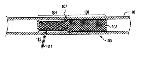
Figs. 1-3 are schematic illustrations of a generally tubular endovascular
prosthesis
100, in accordance with respective applications of the present invention.
Prosthesis 100 is
configured to transition from a radially-compressed state, as described
hereinbelow with
reference to Fig. 7B and 8A, to a radially-expanded state, as shown in Figs. 1-
3 and some
of the other figures. Prosthesis 100 is also configured to transition between
an initial
folded state, as described hereinbelow with reference to Figs. 4, 5, and 7C-D,
to a
subsequent unfolded state, as shown in Figs. 1-3 and some of the other
figures.
Prosthesis 100 comprises a first structural portion 101, which has first and
second
ends 102 and 103, and a second structural portion 104, which has first and
second ends
105 and 106. Each of the first and second structural portions is generally
cylindrical when
the prosthesis assumes the radially-expanded and unfolded states. In the
unfolded state
shown in Fig. 1-3, second structural portion 104 is no longer positioned
within first
structural portion 101, and second end 103 of first structural portion 101 and
second end
106 of second structural portion 104 are positioned at opposite ends of
prosthesis 100.
The first and second structural portions comprise a plurality of structural
stent
9
CA 02767596 2012-01-09
WO 2011/004374 PCT/1L2010/000549
elements, which typically comprise a metal, such as a super-elastic alloy,
e.g., Nitinol.
For some applications, the prosthesis is relaxed in the radially-expanded
state. For some
applications, the prosthesis is configured to be self-expandable. For some
applications,
the structural stent elements are braided or woven, such as for applications
in which the
structural stent elements comprise the super-elastic alloy.
First end 102 of first structural portion 101 and first end 105 of second
structural
portion 104 meet each other at a juncture 107 axially between first structural
portion 101
and second structural portion 104 when the prosthesis assumes the unfolded
state. For
some applications, as shown in Fig. 1, first end 102 of first structural
portion 101 is
shaped so as to define a plurality of first loops, and first end 105 of second
structural
portion 104 is shaped so as to define a plurality of second loops. The first
loops are
interconnected with the second loops so as to define juncture 107. For other
applications,
as shown in Fig. 2, first and second structural portions 101 and 104 are
integral elements
of prosthesis 100. For these applications, joint 107 is optionally defined by
structural
stent elements that are configured to facilitate folding, e.g., the structural
stent elements
may be extended in comparison to other stent elements of the prosthesis.
For some applications, a length of first structural portion 101 is at least 1
cm, no
more than 10 cm, and/or between 1 and 10 cm, such as between 2 and 5 cm, when
prosthesis 100 assumes the radially-expanded and unfolded states. For some
applications,
a length of second structural portion 104 is at least 0.5 cm, no more than 6
cm, and/or
between 0.5 and 6 cm, such as between 1 and 4 cm, when prosthesis 100 assumes
the
radially-expanded and unfolded states. For some applications, when prosthesis
160
assumes the radially-expanded and unfolded states, first structural portion
101 is longer
than second structural portion 104, such as at least 20% longer, no more than
100%
longer, and/or between 20% and 100% longer, such as between 30% and 80%
longer. For
other applications, first and second structural portions 101 and 104 are of
equal length, or
second structural portion 104 is longer than first structural portion 101. In
the latter case,
second end 106 of second structural portion 104 may protrude distally beyond
second end
103 of first structural portion 101 when the prosthesis assumes the initial
folded state
(configuration not shown).
For some applications, a length of prosthesis 100 is at least 1.5 cm, no more
than
16 cm, and/or between 1.5 and 16 cm, such as between 3 and 9 cm, when
prosthesis 100
CA 02767596 2012-01-09
WO 2011/004374 PCT/1L2010/000549
assumes the radially-expanded and unfolded states. For some applications, a
length of
prosthesis 100 is at least 2 cm, no more than 20 cm, and/or between 2 and 20
cm, such as
between 3 and 10 cm, when prosthesis 100 assumes the radially-compressed and
folded
states.
For some applications, a diameter of first structural portion 101 is generally
constant along its length, as shown in Fig. 1, when prosthesis 100 assumes the
radially-
expanded and unfolded states. For example, an outer diameter of first
structural portion
101 may be at least 3 mm, no more than 20 mm, and/or between 3 and 20 mm, such
as
between 4 and 15 mm. For some applications, a diameter of second structural
portion 104
is generally constant along its length, as shown in Fig. 1. For example, an
outer diameter
of second structural portion 104 may be at least 2.5 mm, no more than 20,
and/or between
2.5 and 20 mm, such as between 4 and 12 mm.
For some applications, an average diameter of first structural portion 101 is
greater
than an average diameter of second structural portion 104, such as between 10%
and 40%
greater. The smaller diameter of the second structural portion may increase
the ease of
unfolding the second structural portion from within the first structural
portion, as
described hereinbelow with reference to Figs. 7E-7G and 8B-C. The larger
diameter of
the first structural portion may provide better alignment of the prosthesis
with the wall of
the lumen.
For other applications, the diameters of the structural portions are equal, or
the
diameter of the second structural portion is greater than the diameter of the
first structural
portion. (When the prosthesis assumes the initial folded state, as described
hereinbelow,
even if the diameter of the second structural portion is greater than the
diameter of the
first structural portion, the second structural portion can typically fit
within the first
structural portion. For example, for applications in which the structural
stent elements are
braided, the second structural portion axially expands when radially
compressed.)
For some applications, as shown in Fig. 2, first structural portion 101 is
flared
radially outward at second end 103, and/or second structural portion 104 is
flared radially
outward at second end 106. The main bodies (i.e., the non-flared portions) of
the
structural portions may have the diameters and relative diameters described in
the
preceding paragraphs. The flare at second end 106 may help prevent blood from
entering
the space between second structural portion 104 and the lumen wall, even in
11
CA 02767596 2012-01-09
WO 2011/004374 PCT/1L2010/000549
configurations in which prosthesis 100 does not comprise fluid flow guide 108,
as
described hereinbelow with reference to Fig. 5. (For applications in which
second
structural portion 104 is implanted downstream from first structural portion
104, some
blood generally flows upstream during diastole.)
For some applications, one or more of the flares may be provided in
combination
with the looped junction described hereinabove with reference to Fig. 1, or
the increasing
diameters described hereinbelow with reference to Fig. 3.
For still other applications, as shown in Fig. 3, the diameter of a portion of
first
structural portion 101 (typically near second end 103) increases (such as
monotonically
increases) toward second end 103, and/or the diameter of a portion of second
structural
portion 104 (typically near second end 106) increases (such as monotonically
increases)
toward second end 106. A portion of the increase in the diameter of second
structural
portion 104 is optionally provided by a step, as shown in Fig. 3.
Reference is now made to Figs. 4 and 5, which are schematic cross-sectional
and
perspective illustrations, respectively, of prosthesis 100 in the initial
folded state, in
accordance with an application of the present invention. In the initial folded
sate, second
structural portion 104 is folded into first structural portion 101 at juncture
107, such that
second end 106 of second structural portion 104 axially extends in a direction
from
juncture 107 toward second end 103 of first structural portion 101 (the
direction is
rightward in Figs. 4 and 5). Second end 106 may or may not extend all of the
way to
= second end 103, and optionally extends beyond second end 103.
It is noted that Figs. 4 and 5 show second structural portion 104 folded
within first
structural portion 101 while the second structural portion is radially
expanded. For some
applications, as described hereinbelow with reference to Figs. 7C-F and 8A-B,
the second
structural portion is at least partially (e.g., entirely) radially compressed
while folded
within the first structural portion.
For some applications, as shown in Fig. 5, prosthesis 100 further comprises a
blood-impervious fluid flow guide 108, which at least partially covers second
structural
portion 104. Alternatively or additionally, for some applications, prosthesis
100 further
comprises a blood-impervious fluid flow guide 109, which at least partially
covers first
structural portion 101. For some applications, one or both of the fluid flow
guides is
biodegradable. For example, one or both of the fluid flow guides may comprise
a
12
CA 02767596 2012-01-09
WO 2011/004374 PCT/1L2010/000549
biodegradable polymer, Which may, for example, be selected from the group
consisting
of: starch, gelatin, dextran, dextrin, alginate, hydroxypropyl
methylcellulose,
hydroxypropyl cellulose, polyvinyl alcohol, poly(L-lactic acid), poly(lactide-
co-
glycolide), polyethylene glycol, polycaprolactone, polyphosphate ester,
poly(hydroxy-
butyrate), poly(glycolic acid), poly(DL-lactic acid), poly(amino acid),
chitosan, collagen
and cellulose, polyethylenecarbo-nate, and a mixture thereof.
Reference is made to Figs. 6A-C, which are schematic illustrations of
configurations of prosthesis 100 having an elongated opening 130, in
accordance with
respective applications of the present invention. In these configurations,
second structural
portion 104 is shaped so as to define at least one elongated opening 130
(i.e., a
circumferential discontinuation in the structural stent elements of portion
104) that
extends axially along at least a portion of the second structural portion,
when the
prosthesis assumes the radially-expanded state. For example, the at least one
elongated =
opening may comprise exactly one elongated opening, or two, three, four, or
more
elongated openings. The at least one elongated opening reduces the radial
compressive
strength of second structural portion 104, thereby enabling the second
structural portion to
be more readily folded into and unfolded out of the first structural portion.
Elongated
opening 130 may be implemented in combination with any of the other features
of
prosthesis 100 described herein, including, but not limited to, fluid flow
guide 108.
For some applications, elongated opening 130 extends along only a portion of
second structural portion 104, as shown in Figs. 6A-C, while for other
applications, the
elongated opening extends along the entire length of portion 104
(configuration not
shown). For some applications, elongated opening 130 extends to second end 106
of the
portion 104, as shown in Fig. 6C. For some applications, a length of elongated
opening
130 is at least 2 mm, no more than 30 mm, and/or between 2 and 30 mm, such as
between
4 and 20 mm. For some applications, a length of elongated opening 130 is at
least 20%,
no more than 80%, and/or between 20% and 80% of a length of second structural
portion
104, such as between 30% and 50%.
For some applications, as shown in Figs. 6A and 6C, an arc of the prosthesis
circumscribed by the elongated opening is generally constant along an entire
length of the
elongated opening, such that a width of elongated opening is generally
constant. For
other applications, as shown in Fig. 6B, the arc of the prosthesis
circumscribed by the
13
CA 02767596 2012-01-09
WO 2011/004374 PCT/1L2010/000549
elongated opening is less at a first end of the elongated opening than at a
second end of
the elongated opening, which second end of the elongated opening is closer to
second end
106 of second structural portion 104 than the first end of the elongated
opening is to
second end 106. Alternatively, for some applications, the arc is greater at
the first end of
the elongated opening than at the second end of the elongated opening
(configuration not
shown). For some applications, the arc increases (such as monotonically
increases) from
the first end of the elongated opening to the secOnd end of the elongated
opening, as
shown in Fig. 6B, or from the second end of the elongated opening to the first
end of the
elongated opening (configuration not shown). For example, the elongated
opening may
be generally triangular, as shown in Fig. 6B. For some applications, the arc
of prosthesis .
circumscribed by elongated opening 130 (or by each of elongated openings 130,
if more
than one are provided) is at least 20 degrees, no more than 50 degrees, and/or
between 20
and 30 degrees.
During implantation of the prosthesis, as described hereinbelow with reference
to
Figs. 7A-G and 8A-C, it is important that elongated opening 130 does not
overlap with
the puncture site. In order to enable the surgeon to properly rotationally
orient the
prosthesis to prevent such overlap, the elongated opening(s) and/or another
site on the
prosthesis may be provided with one or more markers indicating the location(s)
of the
elongated opening(s).
For some applications, opening 130 is not elongated, and instead has another
shapes, such as circular or square. Optionally, for these applications, second
elongated
member 114, described hereinbelow with reference to Figs. 7B and 8A, passes
through
opening 130, rather than through second end 106 of second structural portion
104.
Reference is now made to Figs. 7A-G, which are schematic illustrations of a
method for introducing and deploying prosthesis 100 through a puncture site
111 into a
body lumen 110, in accordance with an application of the present invention.
Figs. 8A-C
are schematic cross-sectional illustrations of a portion of the steps of the
method, in
accordance with an application of the present invention. Body lumen 110 may be
a blood
vessel, such as an artery (e.g., the iliac artery, the femoral artery, the
radial artery, or the
brachiocephalic artery), or a corresponding vein (e.g., the iliac vein, the
femoral vein, the
radial vein, the brachiocephalic vein, or the chiocephalic vein, or the
esophageous, or
other segments of the gastro-intestinal tract, such as the small intestine or
large intestine.
14
CA 02767596 2012-01-09
WO 2011/004374 PCT/1L2010/000549
As shown in Fig. 7A, the procedure begins with the insertion of a guidewire
112
through puncture site 111 into body lumen 110. The puncture was typically
previously
made during a transvascular procedure, to enable insertion of a treatment or
diagnostic
device into body lumen 110 (and optionally into another body lumen,
compartment, or
organ thereafter). Prosthesis 100 can generally be used for closing punctures
that are
suitable for delivery of catheters that are essentially unlimited in their
outer diameter.
Typically, the prosthesis is initially stored in sterile packaging in the
radially-compressed
and initial folded states. All or a portion of the elements used to introduce
and deploy the
prosthesis, such as described hereinbelow, may also be stored in the same
sterile
packaging, or in separate sterile packaging.
As shown in Figs. 7B and 8A, prosthesis 100 is introduced over guidewire 112
in
the radially-compressed and initial folded states. The prosthesis is typically
positioned
such that juncture 107 (which is located at the proximal end of the prosthesis
when the
prosthesis is in the initial folded state) is between about 0.5 and 3 cm
distally from
puncture site 111, such as between 0.5 and 2 cm, and/or at a distance from the
puncture
site of between 0.1 and 1.5 times a diameter of the lumen at the puncture
site. Typically,
the prosthesis is oriented such that juncture 107 is between puncture site 111
and second
end 103 of first structural portion 101. For some applications, the prosthesis
is introduced
and deployed using a deployment tool, which comprises a first elongated member
113,
which is initially in contact with first structural portion 101, and/or a
second elongated
member 114, which is initially in contact with second structural portion 104.
First
elongated member 113 and prosthesis 100 are arranged such that axial motion of
first
elongated member 113 with respect to prosthesis 100 results in radial
expansion of first
structural portion 101. For example, such axial motion may be caused by
proximally
pulling the first elongated member toward the surgeon. Second elongated member
114
and prosthesis 100 are arranged such that axial inotion of second elongated
member 114
with respect to prosthesis 100 transitions the prosthesis to the unfolded
state. For
example, such axial motion may be caused by proximally pulling the second
elongated
member toward the surgeon. For some applications, for example as described in
more
detail below, second elongated member 114 and prosthesis 100 are arranged such
that the
axial motion of the second elongated member with respect to the prosthesis
transitions the
prosthesis to the unfolded state and results in radial expansion of the second
structural
portion.
CA 02767596 2012-01-09
WO 2011/004374 PCT/1L2010/000549
For some applications, first shaft member 113 comprises a first generally
tubular
sheath, as shown in Figs. 7B, 7C, and 8A. The first sheath is initially
externally
positioned surrounding at least a portion of first structural portion 101,
such as the entire
first structural portion. The first sheath initially holds prosthesis 100 in
the radially-
compressed state.
As shown in Figs. 7C, 7D, and 8B, the first sheath is withdrawn proximally
from
the prosthesis, allowing first structural portion 101 to expand radially
outward. To enable
this withdrawal of the first sheath, the first sheath is slidable with respect
to the first
structural portion; optionally, the first sheath may be internally lubricated.
For some
applications, as shown in the figures, second structural portion 104 remains
at least
partially radially compressed toward a central longitudinal axis of the
prosthesis.
Alternatively, the second structural portion expands radially outward at this
stage of
deployment (configuration not shown).
For some applications, as shown in Figs. 7D-F, and most clearly in Figs. 8A-C,
second elongated member 114 is initially positioned within the second
structural portion.
In other words, the second elongated member is positioned between the second
structural
portion and a central longitudinal axis of the prosthesis. Withdrawing the
second
elongated member in a proximal direction, as shown in Figs. 7E-F and 8B-C,
causes
second structural portion 104 to unfold from within first structural portion
101. For some
applications, the second elongated member and the second structural portion
are
configured such that the second elongated member is frictionally adherent to
the second
structural portion. As a result, the second elongated member pulls the second
structural
portion proximally as the second elongated member is withdrawn proximally.
Alternatively or additionally, second elongated member 114 is shaped so as to
define or
comprises an engagement element 115 at a distal end of the second elongated
member, as
shown in Figs. 8A-C. The engagement element is configured to removably engage
second end 106 of second structural portion 104, and to pull second 106
proximally as
second elongated member 114 is withdrawn proximally. For some applications,
the
second elongated member comprises silicone, a high-friction elastomer, or a
fluoropolymer, such as PTFE, PET, or PEEK.
For some applications, the second elongated member comprises a second
generally tubular sheath, which may comprise, for example, silicone,
polyurethane,
16
CA 02767596 2012-01-09
WO 2011/004374 PCT/1L2010/000549
fluoropolymer, or another material. Typically, the second sheath is shaped so
as to define
an internal lumen sized to allow passage therethrough of guidewire 112. (For
clarity of
illustration, guidewire 112 is not shown in Figs. 8A-C, although it is
typically provided.)
Alternatively, for some applications, first elongated member 113 comprises a
shaft, and/or second elongated member 114 comprises a shaft (configuration not
shown).
Alternatively or additionally, second elongated member 114 is removably
coupled to
second end 106 of second structural portion 104. For some applications,
elongated
member 113 comprises an engagement element that is removably coupled to second
end
103 of first structural portion 101 (configuration not shown). The engagement
element
initially holds the prosthesis in the radially-compressed state. Upon removal
of the
engagement element, the prosthesis transitions to the radially-expanded state.
Upon complete proximal withdrawal of second elongated member 114 from
second structural portion 104, prosthesis 100 completes the transition to the
unfolded
state, as shown in Fig. 7G. A portion of second structural portion 104 extends
alongside
puncture site 111 in body lumen 110, thereby at least partially covering and
blocking
blood flow to the puncture site. The prosthesis is typically left permanently
in place in the
lumen. For some applications, all or a portion of the structural stent
elements is
biodegradable (for example, stent crowns may be biostable, while connective
members
that connect the stent crowns may be biodegradable, such that flexibility of
the blood
vessel is maintained in the long term and future percutaneous procedures are
facilitated.
The structural stent elements of second structural portion 104 provide at
least
partial tissue scaffolding to enable hemostasis, and provide a surface that
stimulates blood
coagulation. The stent elements also reduce blood flow in the vicinity of
puncture site
111, enabling quicker healing of the puncture site. First structural portion
101 helps hold
the entire prosthesis in place by providing good contact with the lumen wall.
The first
structural portion also may impede blood penetration into the space between
the second
structural portion and the puncture site.
The curative features of prosthesis 100 described in the preceding paragraph
are
provided by prosthesis 100 even in configurations that do not include fluid
flow guide
108, described hereinabove with reference to Fig. 5, particularly if the
structural stent
elements have a high density, realized, for example, by a tight braided
structure. In
configurations that include fluid flow guide 108, the fluid flow guide also
helps seal the
17
CA 02767596 2012-01-09
WO 2011/004374 PCT/1L2010/000549
puncture site, and stimulates tissue growth and coagulation.
Prosthesis 100 is typically a stand-alone device, which is not integrated or
coupled
to any other implantable treatment or diagnostic devices. Alternatively, for
some
applications, prosthesis 100 may be coupled to or integral with another
implantable
treatment or diagnostic device, such as a stent component of another device,
e.g., an
endovascular stent-graft, such as for treating an aortic aneurysm.
As used in the present application, including the claims, "proximal" means
toward
puncture site 111 (and the surgeon), and "distal" means away from the puncture
site (and
the surgeon). For applications in which the body lumen is a blood vessel,
distal may be
either upstream or downstream, depending on the direction in which the
prosthesis is
advanced into the blood vessel after passing through the puncture site.
It will be appreciated by persons skilled in the art that the present
invention is not
limited to what has been particularly shown and described hereinabove. Rather,
the scope
of the present invention includes both combinations and subcombinations of the
various
features described hereinabove, as well as variations and modifications
thereof that are
not in the prior art, which would occur to persons skilled in the art upon
reading the
foregoing description.
18