Note: Descriptions are shown in the official language in which they were submitted.
CA 02770934 2012-02-10
WO 2011/033001 PCT/EP2010/063579
Title: Method of Drilling a Subterranean Borehole
Description of Invention
The present invention relates to a method of drilling a subterranean borehole,
particularly, but not exclusively, for the purpose of extracting hydrocarbons
from a subterranean oil reservoir.
The drilling of a wellbore is typically carried out using a steel pipe known
as a
drill string with a drill bit on the lowermost end. The entire drill string
may be
rotated using an over-ground drilling motor, or the drill bit may be rotated
independently of the drill string using a fluid powered motor or motors
mounted
in the drill string just above the drill bit. As drilling progresses, a flow
of mud is
used to carry the debris created by the drilling process out of the wellbore.
Mud is pumped through an inlet line down the drill string to pass through the
drill bit, and returns to the surface via the annular space between the outer
diameter of the drill string and the wellbore (generally referred to as the
annulus). When drilling off-shore, a riser is provided and this comprises a
larger diameter pipe which extends around the drill string upwards from the
well head. The annular space between the riser and the drill string,
hereinafter
referred to as the riser annulus, serves as an extension to the annulus, and
provides a conduit for return of the mud to mud reservoirs.
Mud is a very broad drilling term, and in this context it is used to describe
any
fluid or fluid mixture used during drilling and covers a broad spectrum from
air,
nitrogen, misted fluids in air or nitrogen, foamed fluids with air or
nitrogen,
aerated or nitrified fluids to heavily weighted mixtures of oil or water with
solid
particles.
CA 02770934 2012-02-10
WO 2011/033001 PCT/EP2010/063579
2
The mud flow also serves to cool the drill bit, and in conventional
overbalanced
drilling, the density of the mud is selected so that it produces a pressure at
the
bottom of the wellbore (the bottom hole pressure or BHP) which is high
enough to counter balance the pressure of fluids in the formation ("the
formation pore pressure"), thus substantially preventing inflow of fluids from
formations penetrated by the wellbore entering into the wellbore. If the BHP
falls below the formation pore pressure, an influx of formation fluid - gas,
oil or
water, can enter the wellbore in what is known as a kick. On the other hand,
if
the BHP is excessively high, it might be higher than the fracture strength of
the
rock in the formation. If this is the case, the pressure of mud at the bottom
of
the wellbore fractures the formation, and mud can enter the formation. This
loss of mud causes a momentary reduction in BHP which can, in turn, lead to
the formation of a kick.
Conventional overbalanced drilling can be particularly problematic when
drilling through formations which are already depleted to the extent that the
formation pressure has fallen below the original formation pressure, or have a
narrow operational window between the BHP at which the formation will
fracture ("the fracture pressure") and the formation pressure. In these cases,
it
is difficult to avoid drilling problems such as severe loss of circulation,
kicks,
formation damage, or formation collapse.
These problems may be minimised by using a technique known as managed
pressure drilling, which is seen as a tool for allowing reduction of the BHP
while retaining the ability to safely control initial reservoir pressures.
In managed pressure drilling, the annulus or riser annulus is closed using a
pressure containment device such as a rotating control device, rotating blow
out preventer (BOP) or riser drilling device. This device includes sealing
elements which engage with the outside surface of the drill string so that
flow
CA 02770934 2012-02-10
WO 2011/033001 PCT/EP2010/063579
3
of fluid between the sealing elements and the drill string is substantially
prevented, whilst permitting rotation of the drill string. The location of
this
device is not critical, and for off-shore drilling, it may be mounted in the
riser at,
above or below sea level, on the sea floor, or even inside the wellbore. A
flow
control device, typically known as a flow spool, provides a flow path for the
escape of mud from the annulus / riser annulus. After the flow spool there is
usually a pressure control manifold with at least one adjustable choke or
valve
to control the rate of flow of mud out of the annulus / riser annulus. When
closed during drilling, the pressure containment device creates a back
pressure in the wellbore, and this back pressure can be controlled by using
the
adjustable choke or valve on the pressure control manifold to control the
degree to which flow of mud out of the annulus / riser annulus is restricted.
During managed pressure drilling it is known for an operator, during drilling,
to
monitor and compare the flow rate of mud into the drill string with the flow
rate
of mud out of the annulus / riser annulus to detect if there has been a kick
or if
drilling fluid is being lost to the formation. A sudden increase in the volume
or
volume flow rate out of the annulus / riser annulus relative to the volume or
volume flow rate into the drill string indicates that there has been a kick,
whilst
a sudden drop in the volume or volume flow rate out of the annulus / riser
annulus relative to the volume or volume flow rate into the drill string
indicates
that the mud has penetrated the formation. Appropriate control procedures
may then be implemented. Such a system is described, for example, in
US704423.
According to a first aspect of the invention we provide a method of drilling a
subterranean well bore using a tubular drill string, the method including the
steps of injecting a drilling fluid into the well bore via the drill string
and
removing said drilling fluid from an annular space in the well bore around the
drill string via a return line, wherein the method further includes
oscillating the
CA 02770934 2012-02-10
WO 2011/033001 PCT/EP2010/063579
4
pressure of the fluid in the annular space in the well bore, and monitoring
the
rate of flow of fluid along the return line.
Preferably the return line is provided with a choke which restricts the flow
of
fluid along the return line and which is operable to vary the degree to which
the
flow of fluid along the return line is restricted, and the oscillating of the
pressure of the fluid in the annular space in the well bore is achieved by
oscillating the choke to alternately increase and decrease the degree to which
the flow of fluid along the return line is restricted.
The return line may be provided with a main choke and an auxiliary choke, the
auxiliary choke being located in a branch line which extends from the return
line upstream of the main choke to the return line downstream of the main
choke. In this case, the oscillating of the pressure of the drilling fluid in
the
well bore is preferably achieved by oscillating the auxiliary choke to
alternately
increase and decrease the degree to which the flow of fluid along the return
line is restricted.
Preferably the rate of flow of the drilling fluid along the return line is
monitored
using a flow meter which is connected to a processor which records the rate of
flow of fluid along the return line over time.
The flow meter is preferably located in the return line upstream of the choke
or
chokes.
The method preferably includes the steps of comparing the rate of flow of
fluid
along the return line when oscillating the pressure of the fluid in the well
bore
prior to drilling into a formation with the rate of flow of fluid along the
return line
when oscillating the pressure of the fluid in the well bore whilst drilling
through
a formation including a reservoir of formation fluid.
CA 02770934 2012-02-10
WO 2011/033001 PCT/EP2010/063579
The method may include the steps of, whilst drilling through a formation
including a reservoir of formation fluid, progressively increasing the mean
pressure of fluid in the well bore whilst oscillating the pressure of fluid in
the
well bore, the amplitude of the pressure oscillations being maintained at a
5 generally constant level.
The method may include the steps of, whilst drilling through a formation
including a reservoir of formation fluid, progressively decreasing the mean
pressure of fluid in the well bore whilst oscillating the pressure of fluid in
the
well bore, the amplitude of the pressure oscillations being maintained at a
generally constant level.
An embodiment of the invention will now be described, by way of example
only, with reference to the following figures;
FIGURE 1 shows a schematic illustration of a drilling system adapted for
implementation of the drilling method according to the invention,
FIGURE 2 shows plots of BHP and returned mud flow rate over time when
there is a step increase in BHP during standard managed pressure drilling,
FIGURE 3 shows plots of BHP and returned mud flow rate over time when the
method according to the invention is used and the BHP is maintained between
the formation pore pressure and the formation fracture pressure,
FIGURE 4 shows a plot of well depth versus pressure for an example well
bore,
FIGURE 5 shows plots of BHP and returned mud flow rate over time when the
method according to the invention is used and the BHP peaks exceed the
formation fracture pressure,
CA 02770934 2012-02-10
WO 2011/033001 PCT/EP2010/063579
6
FIGURE 6 shows plots of BHP and returned mud flow rate over time when the
method according to the invention is used and the mean BHP is reduced so
that the BHP peaks no longer exceed the formation fracture pressure,
FIGURE 7 shows plots of BHP and returned mud flow rate over time when the
method according to the invention is used and the minimum BHP falls below
the formation pore pressure,
FIGURE 8 shows plots of BHP and returned mud flow rate over time when the
method according to the invention is used and the mean BHP is increased so
that the minimum BHP no longer falls below the formation pore pressure,
FIGURE 9 shows an illustration of a cross-section through an embodiment of
choke suitable for use in a drilling system according to the invention,
FIGURE 10 shows a plan view of a cut-away section of the choke along line X
shown in Figure 9,
FIGURES 11 a and 11 b show a cut-away section of the choke along the line Y
shown in Figure 9, with Figure 11 a showing the choke in a fully open
position,
and Figure 11 b showing the choke in a partially open position.
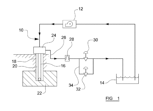
Referring first to Figure 1, there is shown a schematic illustration of a
drilling
system 10 comprising at least one mud pump 12 which is operable to draw
mud from a mud reservoir 14 and pump it into a drill string 16 via a
standpipe.
The drill string 16 extends into a wellbore 18, and has a drill bit at its
lowermost end (not shown).
As described above, the mud injected into the drill string 16 passes from the
drill bit 16a into the annular space in the wellbore 18 around the drill
string 18
(hereinafter referred to as the annulus 20). In this example, the wellbore 18
is
shown as extending into a reservoir / formation 22. A rotating control device
24 (RCD) is provided to seal the top of the annulus 20, and a flow spool is
CA 02770934 2012-02-10
WO 2011/033001 PCT/EP2010/063579
7
provided to direct mud in the annulus 20 to a return line 26. The return line
26
provides a conduit for flow of mud back to the mud reservoir 14 via a
conventional arrangement of shakers, mud/gas separators and the like (not
shown).
In the return line 26 there is a flow meter 28, typically a Coriolis flow
meter
which may be used to measure the volume flow rate of fluid in the return line
26. Such flow meters are well known in the art, but shall be described briefly
here for completeness. A Coriolis flow meter contains two tubes which split
the fluid flowing through the meter into two halves. The tubes are vibrated at
their natural frequency in an opposite direction to one another by energising
and electrical drive coil. When there is fluid flowing along the tubes, the
resulting inertial force from the fluid in the tubes causes the tubes to twist
in
the opposite direction to one another. A magnet and coil assembly, called a
pick-off, is mounted on each of the tubes, and as each coil moves through the
uniform magnetic field of the adjacent magnet it creates a voltage in the form
of a sine wave. When there is no flow of fluid through the meter, these sine
waves are in phase, but when there is fluid flow, the twisting of the tubes
causes the sine waves to move out of phase. The time difference between the
sine waves, 6T, is proportional to the volume flow rate of the fluid flowing
through the meter.
In the system described above, the flow meter 28 measures the returned mud
flow rate.
The return line 26 is also provided with a main choke 30 and an auxiliary
choke 32. The main choke 30 is downstream of the flow meter 28, and is
operable, either automatically or manually, to vary the degree to which flow
of
fluid along the return line 26 is restricted. The auxiliary choke 32 is
arranged
in parallel with the main choke 30, i.e. is placed in an auxiliary line 34 off
the
return line 26 which extends from a point between the flow meter 28 and the
main choke 30 to a point downstream of the main choke 30. In this example,
CA 02770934 2012-02-10
WO 2011/033001 PCT/EP2010/063579
8
the auxiliary choke 32 is movable between a closed position, in which flow of
fluid along the auxiliary line 34 is substantially prevented, and a fully open
position in which flow of fluid along the auxiliary line 34 is permitted
substantially unimpeded by the choke 32. It will be appreciated that, whilst
the
pump 12 is pumping mud into the drill string 16 at a constant rate, operation
of
both the main choke 30 and the auxiliary choke 32 to restrict the rate of
return
of mud from the annulus effectively applies a back-pressure to the annulus 20,
and increases the fluid pressure at the bottom of the wellbore 18 (the bottom
hole pressure or BHP).
The auxiliary line 34 has a smaller diameter than the return line 26 - in this
example the auxiliary line 34 is a 2 inch line, whilst the return line 26 is a
6 inch
line. As such, even when the auxiliary choke 32 is in the fully open position,
a
smaller proportion of the returning mud flows along the auxiliary line 34 than
the return line 26, and operation of the auxiliary choke 32 cannot cause as
much variation in the BHP as operation of the main choke 30. In this example,
movement of the auxiliary choke 32 between the closed position and the fully
open position causes the BHP to vary, in this example by around 10 psi (0.7
bar).
An embodiment of choke suitable for use in the invention is illustrated in
Figures 9, 10, 11 a and 11 b. Whilst the chokes 30, 32 may be any known
configuration of adjustable choke or valve which is operable to restrict the
flow
of fluid along a conduit to a variable extent, they are advantageously air
configured as illustrated in Figures 9, 10, 11 a and 11 b.
Referring now to Figure 9, there is shown in detail a choke 30a having a choke
member 48 which is mounted in a central bore of a generally cylindrical choke
body 50, the choke member 48 comprising a generally spherical ball. The
choke body 50 is mounted in the annulus return line 28, annulus return relief
CA 02770934 2012-02-10
WO 2011/033001 PCT/EP2010/063579
9
line 28c or pressure relief line 28b' so that fluid flowing along the
respective
line 28, 28c, 28b' has to pass through the central bore of the choke body 50.
The diameter of the ball 48 is greater than the internal diameter of the choke
body 50, and therefore the internal surface of the choke body 50 is shaped to
provide a circumferential annular recess in which the ball 48 is seated. The
ball 48 is connected to an actuator stem 52 which extends through an aperture
provided in the choke body 50 generally perpendicular to the longitudinal axis
of the central bore of the choke body 50 into an actuator housing 54. The
actuator stem 52 is a generally cylindrical rod which is rotatable about its
longitudinal axis within the actuator housing 54, and which has a pinion
section
providing radial teeth extending over at least a portion of the length of the
actuator stem 52.
Referring now to Figure 10, four pistons 56a, 56b, 56c, 56d are mounted in the
actuator housing 54, the actuator housing 54 being shaped around the pistons
56a, 56b, 56c, 56d so that each piston 56a, 56b, 56c, 56d engages with the
actuator housing 54 to form a control chamber 58a, 58b, 58c, 58d within the
actuator housing 54. Each piston 56a, 56b, 56c, 56d is provided with a seal,
in
this example an O-ring, which engages with the actuator housing 54 to provide
a substantially fluid tight seal between the piston 56a, 56b, 56c, 56d and the
housing 54, whilst allowing reciprocating movement of the piston 56a, 56b,
56c, 56d in the housing 54. The pistons 56a, 56b, 56c, 56d are arranged
around the actuator stem 52 to form two pairs, the pistons in each pair being
generally parallel to one another and perpendicular to the pistons in the
other
pair. Four apertures 60a 60b, 60c, 60d extend through the actuator housing
54 each into one of the control chambers 58a, 58b, 58c, 58d, and a further
aperture 61 extends through the actuator housing 54 into the remaining,
central, volume of the housing 54 in which the actuator rod 52 is located.
CA 02770934 2012-02-10
WO 2011/033001 PCT/EP2010/063579
Each piston 56a, 56b, 56c, 56d has an actuator rod 62a, 62b, 62c, 62d which
extends generally perpendicular to the plane of the piston 56a, 56b, 56c, 56d
towards the actuator stem 52. Each actuator rod 62a, 62b, 62c, 62d is
provided with teeth which engage with the teeth of the pinion section of the
5 actuator rod 52 to form a rack and pinion arrangement. Translational
movement of the pistons 56a, 56b, 56c, 56d thus causes the actuator rod 52
and ball 48 to rotate.
An electrical or electronic rotation sensor 64, is, in this embodiment of the
invention, mounted on the free end of the actuator stem 52 and transmits to
10 the central drilling control unit an output signal indicative of the
rotational
orientation of the actuator stem 52 and ball 48 relative to the actuator
housing
54 and choke body 50.
The ball 48 is provided with a central bore 48a which is best illustrated in
Figures 11 a and 11 b. The central bore 48a extends through the ball 48 and
has a longitudinal axis B which lies in the plane in which the longitudinal
axis
of the choke body 50 lies. When viewed in transverse cross-section, i.e. in
section perpendicular to its longitudinal axis B, the central bore 48a has the
shape of a sector of a circle, as best illustrated in Figure 11 a, i.e. has
three
major surfaces - one of which forms an arc and the other two of which are
generally flat and inclined at an angle of around 452 to one another. As such,
the central bore 48a has a short side where the two generally flat surfaces
meet and a tall side where the arc surface extends between the two generally
flat surfaces.
The ball 48 is rotatable through 902 between a fully closed position in which
the longitudinal axis B of the central bore 48a is perpendicular to the
longitudinal axis of the choke body 50, and a fully open position in which the
longitudinal axis B of the central bore 48a coincides with the longitudinal
axis
of the choke body 50, as illustrated in Figures 10 and 11 a. When the choke is
CA 02770934 2012-02-10
WO 2011/033001 PCT/EP2010/063579
11
in the fully open position, the entire cross-section of the central bore 48a
is
exposed to fluid in the choke body 50, and fluid flow through the choke body
50 is substantially unimpeded by the ball 48.
Between the fully open and fully closed position, there are a plurality of
partially open positions in which a varying proportion of the cross-section of
the central bore 48a is exposed to fluid in the choke body 50, as illustrated
in
Figure 11 b. When the choke 30a is in a partially open position, flow of fluid
along the choke body 50 is permitted, but is restricted by the ball 48. The
extent to which fluid flow is restricted depends on the proportion of the
central
bore 48a which is exposed to the fluid flow - the closer the ball 48 is to the
fully open position, i.e. the greater the exposed area, the less the
restriction,
and the closer the ball 48 is to the fully closed position, i.e. the smaller
the
exposed area, the greater the restriction.
The ball 48 is oriented in the choke body 50 such that when the choke moves
from the fully closed position to the fully open position, the short side of
the
central bore 48a is exposed first to the fluid in the choke body 50, the tall
side
of the central bore 48a being last to be exposed. The height of the bore 48a
exposed to fluid in the choke body 50 thus increases as the ball 48 is rotated
to the fully open position.
The central bore in a conventional ball valve is generally circular in cross-
sectional area. The use of a central bore 48a with a sector shaped cross-
section is advantageous as this ensures that there is a generally linear
relationship between the angular orientation of the ball 48 and the degree of
restriction of fluid flow along the choke body 50 over at least a substantial
proportion of the range of movement of the ball 48. This means that it may be
possible to control the back pressure applied to the annulus to a higher
degree
of accuracy than in prior art drilling systems.
CA 02770934 2012-02-10
WO 2011/033001 PCT/EP2010/063579
12
The use of a ball valve arrangement is also advantageous because when the
choke is in the fully open position, the cross-sectional area available for
fluid
flow along the valve body 50 is substantially the same as the flow area along
the flow line into the choke. This means that if debris enters the choke and
blocks the central bore 48a of the ball 48 when the choke is in a partially
open
position, the choke can be unblocked and the debris flushed away by moving
the ball 48 to the fully open position.
Whilst the choke 30a, 30b can be hydraulically actuated, preferably it is
pneumatically operated, in this example using compressed air. The apertures
60a, 60b, 60c, and 60d in the actuator housing 54 are connected to a
compressed air reservoir and a conventional pneumatic control valve (not
shown) is provided to control fluid of compressed air to the chambers 58a,
58b, 58c, 58d. Flow of pressurised fluid into the chambers 58a, 58b, 58c, 58d
causes translational movement of the pistons 56a, 56b, 56c, 56d towards the
actuator stem 52, which, by virtue of the engagement of the rods 62a, 62b,
62c, 62d with the pinion section of the actuator stem 52 causes the ball 48 to
rotate towards the fully closed position.
Whilst return of the ball 48 to the open position could be achieved by spring
loading the pistons 56a, 56b, 56c, 56d or the actuator stem 52, in this
example, this is also achieved using fluid pressure. A further aperture 61 is
provided in the actuator housing 54, and this aperture extends into the
central
space in the housing 54 which is enclosed by the pistons 56a, 56b, 56c, 56d.
This aperture 61 is also connected to the compressed air reservoir via a
conventional pneumatic control valve. Flow of pressurised fluid through the
further aperture 61 into this central space causes translational movement of
the pistons 56a, 56b, 56c, 56d away from the actuator stem 52, which, by
virtue of the engagement of the rods 62a, 62b, 62c, 62d with the pinion
section
of the actuator stem 52 causes the ball 48 to rotate towards the fully open
position.
CA 02770934 2012-02-10
WO 2011/033001 PCT/EP2010/063579
13
In this example, therefore, oscillation of the choke 32 is achieved by
changing
the fluid pressure differential across the pistons 56a, 56b, 56c, 56d. This
can
be achieved by supply pressurised fluid to apertures 60a, 60b, 60c, 60d whilst
allowing flow of fluid out of the actuator housing 54 via aperture 61,
followed
by supply of pressurised fluid to aperture 61 whilst allowing flow of fluid
out of
the actuator housing 54 via apertures 60a, 60b, 60c, 60d and then repeating
these steps.
The drilling system is operated as follows. The pump 12 is operated to pump
mud from the reservoir 14 into the drill string 16, while the drill string is
rotated
using conventional means (such as a rotary table or top drive) to effect
drilling.
Mud flows down the drill string 16 to the drill bit 16a, out into the wellbore
18,
and up the annulus 20 to the return line 26, before returning to the reservoir
14
via the flow meter 28, chokes 30, 32, mud/gas separator and shaker. The fluid
pressure at the bottom of the wellbore 18, i.e. the BHP, is equal to the sum
of
the hydrostatic pressure of the column of mud in the wellbore 18, the pressure
induced by friction as the mud is circulated around the annulus (the
equivalent
circulating density or ECD), and the back-pressure on the annulus resulting
from the restriction of flow along the return line 26 provided by the chokes
30,
32 (the wellhead pressure or WHP). The volume flow rate of mud along the
return line 26 is monitored continuously using the output from the flow meter
28.
When the system is operated in accordance with the invention, the auxiliary
choke 32 is operated to move rapidly and repeatedly between the fully open
and the closed positions, so that the WHP and therefore also the BHP,
fluctuate. In this example, the auxiliary choke 32 is operated so that the
variation is WHP and BHP takes the form of a sinusoidal wave. It should be
appreciated, however, that the pressure pulses may be induced on the well
bore 18 as square waves, spikes or any other wave form. By altering the
speed of operation of the auxiliary choke, and the extent to which it is
opened
each time, the frequency and amplitude of the pressure pulses can be varied
CA 02770934 2012-02-10
WO 2011/033001 PCT/EP2010/063579
14
to suit the geometry and depth of the well being drilled, and the formation
pressure operational window of the formation 22.
The desired frequency of this "chattering" of the auxiliary choke can be
calculated according to the well depth to ensure that the resulting pressure
pulses reach the bottom of the wellbore 18. For example, if the speed of
sound in water is 4.4 times the speed of sound in air (i.e. 343 m/sec x 4.4 =
1509 m/sec), and the wellbore 18 is around 6000 m deep, it can be assumed
that the pressure pulses will take 4 seconds to travel the entire depth of the
wellbore 18. The auxiliary choke 32 is therefore oscillated at a frequency of
5
seconds. The frequency may, of course, be increased for shallower wellbores
or decreased further for even deeper wellbore, and is generally in the range
of
between 2 and 10 seconds.
With the 2 inch auxiliary choke described above, the amplitude of the
fluctuation in the BHP being between for example 5 psi (0.3 bar) if the
auxiliary
choke 32 is opened only slightly for each pulse, and, for example, 50 psi (3
bar) if the auxiliary choke 32 is opened fully on each pulse. The amplitude of
the fluctuations or oscillations can be set as desired for a particular
drilling
operation.
Without the chattering of the auxiliary choke 32, the effect of a sudden
increase in the BHP on the returned mud flow rate as measured by the flow
meter 28 is illustrated in Figure 2. This shows that, for a constant inflow
rate,
as the BHP increases, there is a momentary decrease in the returned mud
flow rate, before the returned mud flow rate increases again to its previous
steady state level. This momentary dip is due to the fluid in the well bore 18
being compressed, thus enabling the wellbore to 18 to contain a greater
volume of fluid than before.
The area between the actual returned mud flow rate curve and the steady
state returned mud flow rate, i.e. the shaded area in Figure 2, is known as
the
CA 02770934 2012-02-10
WO 2011/033001 PCT/EP2010/063579
well storage volume. The Well Bore Storage Factor, i.e. the volume of fluid
that enters the well-bore per unit change in BHP can therefore be calculated
by dividing the well storage volume by the change in BHP, in this case 10 psi.
The reverse applies if there is a sudden decrease in the BHP - this causes a
5 momentary increase in the returned mud flow rate.
It will be appreciated, therefore, that, under steady state conditions (i.e.
when
there is no inflow of fluid into the well bore 18 from a formation 22 and no
penetration of mud into the formation 22) oscillation or "chattering" of the
auxiliary choke 32 will result in a corresponding oscillation in the returned
mud
10 flow rate as illustrated in Figure 3. The shaded area under each returned
mud
flow rate peak or above each returned mud flow rate trough can be used to
calculate the Well Bore Storage Factor at that point.
Such steady state conditions would be achieved when drilling through a
formation 22 whilst the BHP is between the formation pore pressure and the
15 formation fracture pressure as illustrated in Figure 4. Under these
conditions,
there is no mud lost to the formation 22, and there is no inflow of fluid from
the
formation into the well bore 18.
As discussed above, if the BHP falls below the formation pore pressure, fluid
will flow from the formation 22 into the well bore 18, or if the BHP exceeds
the
formation fracture pressure, mud will penetrate the formation 22. Both these
events will alter the well storage coefficient, as follows.
If BHP exceeds the formation fracture pressure, and mud is injected into the
formation, there will be a sudden drop in the returned mud flow rate. When the
auxiliary choke 32 is oscillated as described above, if, as drilling
progresses,
the formation fracture pressure drops so that as the BHP oscillates, the peaks
exceed the formation fracture pressure, the momentary loss of mud to the
formation will increase the magnitude of the drop in returned mud flow rate,
as
CA 02770934 2012-02-10
WO 2011/033001 PCT/EP2010/063579
16
illustrated in Figure 5. This will be detected as a sudden increase in the
Well
Bore Storage Factor.
It will therefore be appreciated that by monitoring the returned mud flow rate
whilst oscillating the auxiliary choke as described above, it is possible to
detect
if the BHP has exceeded the formation fracture pressure. This allows the
operator to react by reducing the mean BHP (for example by opening the main
choke 30 slightly) to avoid further loss of mud to the formation 22. Typically
this can be achieved within 3 or 4 oscillations of the auxiliary choke 32.
This
process is illustrated in Figure 6. As the oscillations of the auxiliary choke
32
cause the BHP to exceed the formation fracture pressure only very briefly,
very little mud is lost to the formation before the mud loss event is detected
and the corrective action taken.
If desired, the operator can use this method to determine the formation
fracture pressure. To do this, the auxiliary choke 32 is oscillated whilst the
main choke 30 is operated to gradually increase the extent to which it
restricts
flow of fluid along the return line 26, whilst all other parameters - mud
inflow
rate, speed of rotation of the drill string etc. are kept constant. This
results in a
steady increase in the BHP. When the sudden increase in Well Bore Storage
Factor resulting from the loss of mud to the formation 22 is detected, the
operator knows that the formation fracture pressure has been exceeded, and
can determine the formation fracture pressure from the peak BHP level at that
time.
If the BHP falls below the formation pore pressure, and fluid from the
formation
flows into the well bore 18, there will be a sudden increase in the returned
mud
flow rate due to a very small momentary influx of formation fluid. When the
auxiliary choke 32 is oscillated as described above, if, as drilling
progresses,
the formation pore pressure increases so that as the BHP oscillates, the BHP
troughs fall below the formation pore pressure, the momentary influx of
formation fluid into the well bore 18 will increase the magnitude of the peak
in
CA 02770934 2012-02-10
WO 2011/033001 PCT/EP2010/063579
17
returned mud flow rate, as illustrated in Figure 7. This will also be detected
as
a sudden increase in the well storage coefficient.
It will therefore be appreciated that by monitoring the returned mud flow rate
whilst oscillating the auxiliary choke as described above, an influx of fluid
from
the formation into the well bore 18 can be detected. This allows the operator
to increase the mean BHP (for example by closing the main choke 30 slightly,
or by increasing the mud density) to avoid further influx. Typically this can
be
achieved within 3 or 4 oscillations of the auxiliary choke 32. This process is
illustrated in Figure 8.
As the oscillations of the auxiliary choke 32 cause the BHP to fall below the
formation pore pressure only very briefly, relatively little formation fluid
enters
the well bore before this determination is made and the corrective action
taken. This means that it may be possible to continue drilling whilst the
negligible amount of formation fluid is circulated out of the well bore 18
with
the returned mud, and separated out, for example, using the standard mud /
gas separators.
If desired, the operator can use this method to determine the formation pore
pressure. To do this, the auxiliary choke 32 is oscillated whilst the main
choke
30 is operated to gradually decrease the extent to which it restricts flow of
fluid
along the return line 26, whilst all other parameters - mud inflow rate, speed
of
rotation of the drill string etc. are kept constant. This results in a steady
decrease in the BHP. When the sudden increase in well storage coefficient
resulting from the influx of fluid from the formation 22 is detected, the
operator
knows that the formation pore pressure has been reached, and can determine
the formation pore pressure from the lowest BHP level at that time.
Using the inventive method to determine the formation fracture pressure and
pore pressure can assist in improving the safety of drilling exploration wells
into formations with unknown fracture pressures or pore pressures.
CA 02770934 2012-02-10
WO 2011/033001 PCT/EP2010/063579
18
This method may also be used to differentiate between a formation fluid inflow
or kick, and the effect of formation ballooning.
Formation ballooning occurs in lithologies, such as carbonates (limestone,
chalk,
dolomite) or clastics (shales, mudstones, sandstones). When the well bore
pressure is reduced, these formations tend to expand. The net effect is that
near
the well bore the formation expands in size, which results in a reduction of
the
average diameter along a section of the well bore. As the average diameter is
reduced, the well bore volume is reduced, temporarily increasing the flow rate
out
of the well bore. Conversely, when the BHP is increased, these formations tend
to
contract in the near vicinity of the well bore, resulting in an increase in
well bore
volume and a corresponding reduction in returned mud flow rate out of the well
bore.
Thus, if mud flow to the drill string is stopped to connect a new portion of
drill pipe
to the drill string 16, the ECD frictional pressure is removed from the well,
and the
BHP may drop by typically 200 to 400psi, resulting in an overall increase in
both
the returning mud flow rate, and a corresponding overall increase in the rigs
surface mud tank (or pit) volume. This can be misinterpreted as a kick, or
formation fluid inflow into the well bore 18.
Well ballooning effects can also be the result of drilling mud returning into
the well
bore from the near well bore face. This effect occurs after mud is forced into
the
near well bore face, if the lithologies exposed have the required
permeability.
When the overall pressure in the well bore is reduced, then some of these
drilling
fluids flow and are returned into the well bore.
As well bore ballooning occurs due to a reduction in overall well bore
pressure,
this return of near well bore invaded drilling fluids can result in an overall
increase
in both the returned mud flow rate out of the well bore 18 / annulus 20, and
an
overall increase in the rigs surface mud reservoir volume. Again, in
conventional
CA 02770934 2012-02-10
WO 2011/033001 PCT/EP2010/063579
19
overbalanced drilling or standard MPD operations, this can be misinterpreted
as a
kick, or formation fluid inflow into the well bore 18.
Thus, well bore ballooning effects can be a result of both the expansion of
the
formation lithology, and/or injected drilling fluid returns from the near well
bore
face permeable formations. But, both occur as the BHP is reduced across all
exposed formations in the well bore.
Well bore ballooning effects are seen as after flow, or a continuation of
returned
mud flow, after the rig mud pumps have been stopped. Returned flow from the
well can continue for some time, after the rigs pumps are stopped, and then
gradually drop off, or slow down in rate. This continuation of mud return flow
after
the rig mud pumps are turned off can be misinterpreted as a kick, and cause a
loss of rig time, as the well is shut in and kick procedures are followed.
The inventive method can be used to effectively and instantaneously
differentiate
between well bore ballooning effects and a kick, using two methods;
A formation fluid influx or kick will immediately be noted as momentary
increase in
the returned mud flow rate peaks as described above, whereas well bore
ballooning will result in an overall increase in returned drilling fluid mud
flow rate
out of the well bore and will be seen as a different trend pattern on the flow
rate
out, as an overall increase not related to BHP dips.
Moreover, despite being relatively insignificant, formation fluid inflow into
the well
bore, resulting in returning mud flow rate peak increases in magnitude, will
be
larger than flow rate out increases on flow rate peaks due to well bore
ballooning.
This is because formation fluid inflows or kicks would normally be composed of
either hydrocarbon gas, or condensate or crude oil with a proportion of gas
cut, or
hydrocarbon Gas Oil Ratio (GOR), whereas the well ballooning is caused in
either
by an influx of mud, or expansion of the formation, neither of which involve
the
expansion of a gas.
CA 02770934 2012-02-10
WO 2011/033001 PCT/EP2010/063579
Thus, the system software will be configured and calibrated to differentiate
between well bore ballooning and a formation fluid inflow into the well bore.
Ideally the system is calibrated by monitoring the returned mud flow rate
during
oscillation or "chattering" of the auxiliary choke 32 prior to drilling out
the casing
5 shoe into any open hole section. At this point it is known that no open
formation
is exposed to the well bore 18, and therefore there cannot be any influx of
formation fluid or loss of mud to the formation. The returned mud flow rate
profile
at this point is therefore representative of the steady state condition
illustrated in
Figure 4, and this can be compared with the returned mud flow rate profile
when
10 drilling into the formation 22 to establish if there has been formation
fluid influx or
mud loss.
The flow meter 28 is connected to an electronic processor which is records the
volume flow rate along the return line 26 over time. The sudden change in Well
Bore Storage Factor brought about by loss of mud to the formation or an influx
of
15 formation fluid into the well bore 18 can be detected in a number of ways.
The
processor can simply be programmed to monitor the amplitude of the volume flow
rate oscillations, as a change in Well Bore Storage Factor increases these
amplitudes. Alternatively, as a change in Well Bore Storage Factor manifests
itself as a change in the area under a flow rate peak, or above a flow rate
trough
20 (the shaded areas in Figures 3, 5 and 7, and the processor can be
programmed
to integrate the volume flow rate v. time curve to determine these areas.
Finally,
for an even more sensitive analysis, the processor can be programmed to plot
the
differential of the volume flow rate v. time curves.
The method described in this patent can be used in various different drilling
modes including managed pressure drilling with a hydrostatically underbalanced
mud weight, managed pressure drilling with a hydrostatically overbalanced mud
weight, and pressurised mud cap drilling. In managed pressure drilling with a
hydrostatically underbalanced mud weight, the hydrostatic pressure of the
column
of mud is less than the formation pore pressure, and the BHP is increased to
CA 02770934 2012-02-10
WO 2011/033001 PCT/EP2010/063579
21
exceed the formation pore pressure by virtue of the frictional effects of
circulating
mud around the well bore 18 and the back pressure (WHP) applied by the chokes
30, 32. In managed pressure drilling with a hydrostatically overbalanced mud
weight, the hydrostatic pressure of the column of mud is greater than the
formation pore pressure, and the BHP is further increased by virtue of the
frictional effects of circulating mud around the well bore 18 and the back
pressure
(WHP) applied by the chokes 30, 32.
Finally, pressurised mud cap drilling employs a dual gradient / density
drilling mud
column with a heavier weigh or density of mud being circulated in the top
portion
of the well bore and a lighter weight or density mud being circulated into the
well
bore below the high density mud cap. The well remains totally closed and there
is no return of well bore fluids through the return line 26, but flow can be
artificially
kept by injecting fluid at the top of the well bore and returning it through
the
chokes. In this case, since drilling fluid is intentionally lost to the
formation during
drilling, the method can only be used as a means of kick detection, and it
would
not be used to determine the formation fracture pressure or to detect loss of
drilling fluid to the formation.
As mentioned above, whilst in this example, the oscillations applied to the
auxiliary choke 32 give rise to generally sinusoidal waveforms, this need not
be
the case, and other wave forms or pulses can be applied. Indeed, it may be
advantageous for the oscillations to give rise to more triangular peaks and
troughs in BHP, as this may further assist in minimising the amount of
formation
fluid influx or mud loss in the event that the minimum BHP falls below the
formation pore pressure or the peak BHP exceeds the formation fracture
pressure.
It should be appreciated that, whilst in this example, an auxiliary choke 32
is
used to provide the fluctuations in BHP, this need not be the case, and the
main choke 30 may be used to do this. As such, it is not essential for the
drilling system 10 include an auxiliary choke as described above, and the
CA 02770934 2012-02-10
WO 2011/033001 PCT/EP2010/063579
22
pressure oscillations can be applied any other way, for example by varying the
rig pump speed.
When used in this specification and claims, the terms "comprises" and
"comprising" and variations thereof mean that the specified features, steps or
integers are included. The terms are not to be interpreted to exclude the
presence of other features, steps or components.
The features disclosed in the foregoing description, or the following claims,
or
the accompanying drawings, expressed in their specific forms or in terms of a
means for performing the disclosed function, or a method or process for
attaining the disclosed result, as appropriate, may, separately, or in any
combination of such features, be utilised for realising the invention in
diverse
forms thereof.