Note: Descriptions are shown in the official language in which they were submitted.
CA 02772387 2012-02-27
WO 2011/034721 PCT/US2010/047253
INTRUSION DETECTION AND TRACKING SYSTEM AND METHODS
BACKGROUND OF THE INVENTION
1. Field of the Invention
[0001] The present invention relates to an intrusion detection and tracking
system.
Specifically, the present invention is for an intrusion detection and tracking
system for an
area or perimeter having an ad-hoc wireless network.
2. Background Information
[0002] Area intrusion detection based on ad-hoc wireless sensor networks
requires
the use of energy demanding and relatively costly sensors for their operation.
Reliable
accurate sensors with low sensitivity to environmental changes are both costly
and power
demanding. These limitations render such networks unsuitable for use in area
(perimeter
or border) intrusion detection applications where low cost, extended sensing
range and
power autonomy are three of the most important requirements driving the design
of the
system. Such conflicting performance and cost requirements frequently lead to
compromises in the design of wireless sensor networks.
[0003] New designs for lower cost sensors appear continuously in the market.
However, in an attempt to reduce production cost, greater demand is being
imposed on the
processing unit of the wireless nodes of the network. This increased demand
increases
energy consumption by the nodes which, in turn, negatively impacts energy
autonomy of
the system. Attempts have been made to increase the range of the sensors from
a few feet
to ten feet or greater. However, the increased cost and complexity of the
enhanced sensors
rendered them unsuitable for wireless network area intrusion detection
application. More
complex software algorithms were developed to produce energy efficient
wireless
networks for the purpose of maximizing the autonomy of wireless network
intrusion
detection systems. The majority of these attempts focused on producing
efficient routing
algorithms for the purpose of minimizing the average transmission time of the
wireless
nodes of the sensor networks, thus reducing their energy consumption. However,
this
required the use of an increased number of higher power processing units.
[0004] In view of the above, it will be apparent to those skilled in the art
that a
need exists for an improved intrusion detection system. This invention
addresses this need
as well as other needs, which will become apparent to those skilled in the art
from this
disclosure.
1
CA 02772387 2012-02-27
WO 2011/034721 PCT/US2010/047253
SUMMARY OF THE INVENTION
[0005] It is an object of the present invention to provide an area intrusion
detection
and tracking system that is energy efficient and uses an ad-hoc wireless
network.
In order to achieve the above-mentioned object and other objects of the
present invention,
an intrusion detection and tracking system is provided that comprises a
plurality of nodes,
a data processor (DP) and a gateway. The nodes are disposed about an area and
form a
wireless network to be monitored, the nodes being configured to receive data
and transmit
data frames with a signal strength indicator and/or a link quality indicator
in the frames.
The DP is communicatively connected to the network and configured to analyze
variations
in the signal strength indicator and/or link quality indicator to detect and
track
disturbances to an electromagnetic field in the area. The gateway is
configured to form a
data link between the network and the DP.
[0006] With this particular arrangement, a system for detecting intrusions by
an
object in a given area is provided. By using a plurality of nodes to monitor
disturbances in
an electromagnetic field in a given area, objects which intrude upon the area
(and thus
cause the disturbances in the electromagnetic field) can be identified. By
determining
which ones of the plurality of nodes detect disturbances, a path of the
intruding object
through the area can be identified. In one embodiment, the system detects an
intrusion by
monitoring variations in one or more of the signal strength and/or link
quality indicators.
[0007] In one embodiment, the system detects an intrusion by monitoring
variations in one or more of the indicators. In one embodiment, the signal
strength
indicator is Received Signal Indicator (RSSI) and the link quality indicator
is a Link
Quality Index (LQI).
[0008] In one embodiment, the nodes are configured with an adaptable
transmission rate.
[0009] In one embodiment, the DP triggers the nodes into a self-configuring
mode
in which all nodes auto-adjust their transmission power. In one embodiment,
the DP is
configured to calculate successive levels of detection confidence to provide
false detection
probabilities.
2
CA 02772387 2012-02-27
WO 2011/034721 PCT/US2010/047253
[0010] In one embodiment, the transmission power is adjusted so that the
transmission is received by first and second tier neighboring nodes.
[0011] In one embodiment, levels of detection confidence are directly related
to a
plurality of layers of detection.
[0012] In one embodiment, a first layer of detection is performed at the nodes
and
in one embodiment, the first layer of detection at the nodes triggers one or
more of the
nodes to transmit at a higher transmission rate. In one embodiment, each layer
of
detection after the first layer of detection is performed at the DP.
[0013] In accordance with a further aspect, a method for monitoring an area
comprises disposing a plurality of nodes about the area to be monitored, each
of the
plurality of nodes configured to produce an electromagnetic field in the area.
The method
further comprises forming a wireless network among the plurality of nodes,
configuring
each of the plurality of nodes to receive data and transmit data frames with
at least some of
the frames having a signal strength indicator and/or a link quality indicator,
and analyzing,
in a data processor (DP), variations in the signal strength indicator and/or
link quality
indicator to detect and track disturbances to the electromagnetic field in the
area.
[0014] With this particular arrangement, a method for detecting intrusions in
a
given area is provided. By using a plurality of nodes to monitor disturbances
in an
electromagnetic field in a given area, objects which intrude upon the area can
be
identified. By determining which ones of the plurality of nodes detect
disturbances, a path
of the intruding object can be identified. In one embodiment, the method
further
comprises detecting an intrusion by monitoring variations in one or more of
the indicators.
[0015] In one embodiment, the nodes are configured with an adaptable
transmission rate.
[0016] In one embodiment, the DP triggers the nodes into a self-configuring
mode
in which all nodes auto-adjust their transmission power. In one embodiment,
the method
3
CA 02772387 2012-02-27
WO 2011/034721 PCT/US2010/047253
further comprises adjusting transmission power so that the transmission is
received by first
and second tier neighboring nodes.
[0017] In one embodiment, the method further comprises calculating successive
levels of detection confidence to provide false detection probabilities. In
one embodiment,
this is done in the DP.
[0018] In accordance with a still further aspect, a method for monitoring an
area
comprises forming a wireless network among a plurality of nodes with each of
the nodes
configured to produce an electromagnetic field in the area wherein the
electromagnetic
field produced by each node has a strength sufficient such that it can be
detected by at
least one other of the plurality of nodes; configuring each of the plurality
of nodes to
receive data and transmit data frames with at least some of the frames having
a signal
strength indicator and/or a link quality indicator which provide information
about the
electromagnetic field; and detecting and tracking disturbances to the
electromagnetic field
by analyzing variations in the signal strength indicator and/or link quality
indicator.
[0019] With this particular arrangement, a method for detecting intrusions in
a
given area using a plurality of nodes is provided.
[0020] In one embodiment, the analyzing is performed by a data processor (DP)
and the method further comprises forming a data link between the wireless
network and
the DP. In one embodiment, the detecting is performed at the DP.
[0021] In one embodiment, in response to disturbances to the electromagnetic
field
being detected at a first one of the plurality of nodes, transmitting
information from the
first one of the plurality of nodes at a transmission rate which is higher
than a transmission
rate of at least some other ones of the plurality of nodes.
[0022] These and other objects, features, aspects and advantages of the
present
invention will become apparent to those skilled in the art from the following
detailed
description, which, taken in conjunction with the annexed drawings, discloses
a preferred
embodiment of the present invention.
4
CA 02772387 2012-02-27
WO 2011/034721 PCT/US2010/047253
BRIEF DESCRIPTION OF THE DRAWINGS
[0022] Referring now to the attached drawings, which form a part of this
original
disclosure:
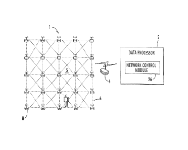
[0023] Figure 1 is a view of an intrusion detection and tracking system
according
to an embodiment of the present invention;
[0024] Figure 2 is a schematic view of a node used in the intrusion detection
and
tracking system;
[0025] Figure 3A is a perspective view of a human target travelling between
two
nodes and a graph of variations caused by the human target;
[0026] Figure 3B is a perspective view of a human target or a vehicle
travelling
between two nodes and a graph of variations caused by the human target and
vehicle;
[0027] Figure 4 is a schematic view of a Layer 1 intrusion confirmation of the
intrusion detection and tracking system;
[0028] Figure 5 is a schematic view of a Layer 2 intrusion confirmation of the
intrusion detection and tracking system;
[0029] Figure 6 is a schematic view of a Layers 3 and 4 intrusion
confirmations of
the intrusion detection and tracking system;
[0030] Figure 7 is a schematic view of a Layers 5 and 6 intrusion
confirmations of
the intrusion detection and tracking system; and
[0031] Figure 8 is a view of an intrusion detection and tracking system
according
to another embodiment of the present invention.
DETAILED DESCRIPTION OF THE PREFERRED EMBODIMENTS
[0032] A preferred embodiment of the present invention will now be explained
with reference to the drawings. It will be apparent to those skilled in the
art from this
disclosure that the following description of the embodiment of the present
invention is
provided for illustration only and not for the purpose of limiting the
invention as defined
by the appended claims and their equivalents.
[0033] Referring initially to Figure 1, an intrusion detection and tracking
system
for an area 5 or perimeter is shown generally at 1. The system 1 includes a DP
2, a
gateway 4 and a wireless network 6, which includes a plurality of wireless
transceiver
CA 02772387 2012-02-27
WO 2011/034721 PCT/US2010/047253
nodes 8. As shown in Fig. 2, each node 8 includes a transmitter 10 and a
receiver 12,
which together form a transceiver 14.
[0034] Eliminating the need for external sensors to detect intrusion in the
vicinity
of the individual nodes of wireless sensor networks significantly lessens both
the cost and
the energy requirement of the system. Energy savings are achieved by
completely
eliminating the need for power to drive the sensors and by considerably
decreasing
processing requirement needed to sample a signal. Substitutional functionality
of the
eliminated sensors is achieved by using the communication protocol of the
nodes 8 of the
wireless network 6, which provides ready availability of intrusion sensing
information
without the need for extra processing power. Hence, the intrusion sensing
range of each of
the nodes 8 in the wireless network 6 is increased to the full transmission
range of each
node transmitter 10. Moreover, lower overall system energy requirements allow
the use of
small solar panels 20 to recharge small onboard rechargeable battery cells 18,
thus
increasing autonomy of the system 1.
[0035] The present invention is a novel and cost effective approach to
intrusion
detection and tracking using the disturbance of the electromagnetic field of
low-cost
COTS transceivers in nodes 8 to detect and track targets of interest. The
present invention
eliminates the need of very costly power and communication infrastructures
associated
with current technologies. Unburdened by such infrastructure requirements, the
present
invention can dramatically change how and where perimeter and area (or
border/perimeter) detection will be performed to better protect critical
facilities and the
like.
[0036] The wireless network 6 sets up an electromagnetic field over an area 5,
using nodes 8 having low power miniature commercial off the shelf (COTS)
System on a
Chip (SoC) transceiver devices deployed in a wireless network configuration.
The system
1 analyzes disturbances to the produced electromagnetic field by monitoring a
signal
strength indicator, e.g. the Received Signal Indicator (RSSI), and a link
quality indicator,
e.g. the Link Quality Index (LQI), at the receivers 12 to detect and track
intrusions in the
area 5 or perimeter. This produces an easily deployed, persistent, and very
cost
effective/energy efficient intrusion detection and tracking system 1 to
protect, for example,
critical facilities, military bases or borders.
[0037] One of the biggest issues to intrusion detection systems is high cost
(sensor,
infrastructure, deployment). This cost is usually a result of either the
sensor cost and/or
6
CA 02772387 2012-02-27
WO 2011/034721 PCT/US2010/047253
the power and communication infrastructure cost required to use the sensors.
Since cost is
a major driving factor in procurement of security systems, whether for
perimeter security
or for area security like border protection, many design compromises are made
at the
security system level, resulting in degraded overall system performance. The
present
invention uses low cost transceivers that utilize a communication protocol,
such as but not
limited to the IEEE 802.15.4 communication protocol, to form the wireless
network 6
which not only lowers costs, but also reduces the need for power and
communication
infrastructure, thereby allowing the system 1 of the present invention to be
installed
virtually anywhere that detection and tracking is required.
[0038] The wireless transceiver nodes 8 in the network 6 use a communication
protocol, that includes values for a signal strength indicator and a link
quality indicator in
any transmitted frame. In one embodiment, the communication protocol is the
IEEE
802.15.4 communication protocol, which is intended for industrial and medical
applications. The IEEE 802.15.4 communication protocol includes RSSI and LQI
values
in any transmitted frame. In this embodiment, the system 1 uses electronic
transmissions
made in compliance with this protocol in a new way: to detect and track
intrusions.
[0039] As the transceivers 14 radiate outward from the transmitting nodes' 8
antennae 22, electromagnetic waves are reflected by the obstacles they strike
and have
their directions of travel altered. A fraction of their energy is also
absorbed by the struck
obstacle causing attenuated waves that proceed in the original direction of
travel. As a
result, different out-of-phase direct, reflected, and absorbed waves are
received by the
nodes' 8 antennae 22, and their instantaneous vector sum determines the
received signal
energy.
[0040] Referring to Figs. 3A and 3B, for a stationary transmitter/receiver
pair of
nodes 8, any change in the position of obstacles in the volume of space
covered by the
transmitter 10 (Fig. 2) will affect the received signal strength and the link
quality at the
receiver end. A moving obstacle in the range of the transmitter will "disturb"
the values of
the signal strength indicator and the link quality indicator at the receiver
12, and these
variations can be analyzed to both detect and track intrusions in the covered
area 5.
[0041] Figs 3A and 3B show examples wherein an obstacle passes between two
nodes 8 spaced apart about 25 feet in an outdoor setting with the
transmitter/receiver pair
using the IEEE 802.15.4 protocol. The RSSI value is as reported by the
receiver 12.
Referring to Fig. 3A, the right side of the graph shows the effect on the RSSI
value caused
7
CA 02772387 2012-02-27
WO 2011/034721 PCT/US2010/047253
by a human target H arbitrarily moving between the pair of nodes 8. Referring
to Fig. 3B,
the RSSI variations in the left portion of the graph are caused by a human
target H walking
along an approximate center line between the nodes 8. The right portion of the
graph in
Fig. 3B shows RSSI variations caused by a vehicle V driven back and forth
along the same
path.
[0042] Preferably, the nodes 8 are SoCs deployed in a grid along the perimeter
or
border of the area 5 to be monitored, as depicted in Figure 1, to create the
wireless
network 6 that is ad-hoc. While the Figures show the nodes 8 forming an
orderly grid, it
will be apparent to one of ordinary skill in the art from this disclosure that
the nodes 8
need not be located in an orderly manner to form the ad-hoc wireless network
6. In the
system 1 of the present invention, the nodes 8 are scattered on the surface
throughout the
area 5 to be monitored in a way that would setup an electromagnetic field that
would cover
the area 5, i.e., provide surveillance. The spacing of the nodes 8 is
dependent on the
overall size of the area 5 for surveillance, the desired detection accuracy,
and the
corresponding power consumption by each node to attain the desired accuracy.
One or
more gateways 4 are used to form a data link between the network 6 and the DP
2, where
processing software filters, correlates, and analyzes collected signal
strength indicator
values and link quality indicator values from the network 6 for the purpose of
detecting
and tracking disturbances to the electromagnetic field to determine the
presence of
intrusions.
[0043] Under control of a Network Control module 26 shown in Fig. 1 running on
the DP 2, the nodes 8 will be periodically triggered to transition into a
short self-
configuration mode. In this mode, all nodes 8 will auto-adjust their
transmission power
through a succession of synchronized interrogate, listen, and adjust
sequences. Each node
8 will adjust its transmission power so that its transmission is received only
by first and
second tier neighboring nodes 8, the first tier neighboring nodes 8 consist of
the closest
neighboring nodes 8 while the second tier neighboring nodes 8 consist of the
next closest
neighboring nodes 8. Note that, apart from maximizing the lifecycle of the
system 1, this
minimum required power use technique will also positively impact the false
detection
probability of the system. During the self-configuration phase, the nodes 8
become aware
of neighboring nodes 8 and this information is relayed across the network 6 to
ultimately
reach the DP 2. The collected information is then processed and the relative
position of
every node 8 in the network is determined. This information is then used to
inform the
8
CA 02772387 2012-02-27
WO 2011/034721 PCT/US2010/047253
nodes 8 of optimal routes to convey intrusion detection data back to the DP 2.
This
technique will ensure minimal energy consumption by the network 6 thus
contributing to
increasing the system's 1 lifecycle.
[0044] To minimize false detection probability and to allow intrusion tracking
across time through the area 5 for surveillance, the following multi-layered
detection
techniques are used. It should be noted that Layer-0 detection is preferably
performed at
the node level while Layer-1 to Layer-6 detection is preferably performed at
the DP level.
The detection techniques described in the following paragraphs are provided
for purposes
of illustration only and not by way of limitation, and it is to be understood
that other
processing systems may also be used without departing from the scope of the
instant
invention.
Layer-0 Detection
[0045] Layer-0 detection provides a first level improvement on the false
detection
probability. Layer 0 detection is an RSSI/LQI variation dual-threshold
filtering performed
by the software executed by the microcontroller unit 16 of the node 8 to
establish the
presence of an intrusion in its vicinity. The threshold triggering filters out
variations to the
field caused by presence of small volume intrusions objects such as leafs and
branches. It
also causes the nodes 8 to switch to a high transmission rate to produce a
larger amount of
detection data to be correlated by the DP 2 and allow a better resolution into
the nature of
the intrusion.
[0046] For the purpose of conserving energy, achieved by minimizing the
overall
transmission time, the nodes 8 will be transmitting at a low rate during no-
intrusion
periods. This preset transmission rate will be such that nodes 8 will be able
to detect an
intrusion traveling through the surveillance area 5 at a predetermined high
speed. Upon
determining the layer-0 detection, which is achieved at the node level, the
node 8 will
switch to a higher transmission rate and will command neighboring nodes 8,
through
transmitted data, to similarly switch to a higher transmission rate. The low
transmission
rate will be reestablished once the nodes 8 determine a no-intrusion period.
Layer-1 to Layer-4 Multi-Node Detection Correlation
[0047] As the node 8 assumes the transmitter role, the neighboring listening
nodes
8 detect the disturbances to the wireless field caused by the intrusion in the
vicinity of the
nodes 8 and individually compute the variations in RSSI/LQI values (Layer-0)
and this
9
CA 02772387 2012-02-27
WO 2011/034721 PCT/US2010/047253
data, tagged with a serial number of the detecting node 8, is routed to the DP
2. The initial
received data that is correlated as being from a group of nodes 8 listening to
one particular
node 8, defined as a cell, constitutes Layer-1 detection and indicates a good
likelihood of
positive intrusion detection. As a result, a Probable System Intrusion warning
is initiated
with a low value for a Detection Confidence Level (DCL) for the detection in
the cell. As
more detections are received at the DP 2 and are similarly correlated, the
value of the DCL
of the detection in the cell containing the nodes 8 is sequentially increased
to indicate an
increase in the confidence of the Positive System Intrusion warning.
[0048] As other nodes 8, surrounding the cell, assume in succession the
transmitter
role, other neighboring listening nodes 8 detect the disturbances to the
wireless field
caused by the same intrusion. This constitutes Layer-2 to Layer-4 Detection
Correlation
with Layer-4 reached when a preset number of the aforementioned correlations
are
reached. The value of the DCL increases as the Layer-2 to Layer-4 Detection
Correlations
are determined, again indicating a further increase in the confidence of a
Positive System
Intrusion.
Layer-5 Multi-Node Detection Correlation
[0049] As successive Layer-1 to Layer-4 Detection Correlations are asserted,
Layer-5 processing correlates the detection across time within a single cell.
The detection
DCL is increased as additional Layer-5 correlation is performed.
Layer-6 Multi-Node Tracking Correlation
[0050] Layer-6 is used to track the intrusion as it travels across adjacent
cells. An
intrusion that traverses adjacent cells indicates a mobile intrusion and
causes the Positive
System Intrusion to be further affirmed and thus maintained. This is reflected
by an
increase in the value of the DCL. Conversely, a stationary intrusion remaining
within one
cell points to a possible false detection causing the value of the DCL to be
decreased,
indicating a decrease in the confidence of a Positive System Intrusion. If no
further
movement is detected from an intrusion, the intrusion may eventually be
demoted to an
anomaly.
[0051] Fig. 8 illustrates another embodiment of architecture for the system 1.
The
following provides a description of an exemplary operation of the system 1 of
Fig. 1 or 8.
In an initial self-configuration phase, each node 8 becomes aware of its
within-
reach neighboring nodes 8 through synchronized interrogate/listen sequences
and
CA 02772387 2012-02-27
WO 2011/034721 PCT/US2010/047253
accordingly adjusts its transmission power in a way that would allow it to be
heard by a
subset of the node neighbors 8. This allows the nodes 8 to minimize energy use
during
normal intrusion detection operation. This determined subset constitutes the
list of first
and second tier neighboring nodes 8 for which the node 8 monitors the signal
strength
indicator and/or the link quality indicator values, e.g., the RSSI/LQI values,
as it listens to
their transmissions. For this purpose, the node 8 constructs an internal table
of the first
and second tier neighboring node IDs, e.g., serial numbers of the nodes 8,
paired with
undisturbed indicator values, e.g., RSSI/LQI values.
[0052] At the end of the self-configuration phase, each node 8 transmits the
contents of its internal table to be relayed by the downstream nodes 8 to the
DP 2, where
information from all nodes 8 is used to construct, using triangulation and
node IDs
correlation, a relative position geographical map of the nodes 8 in the
network 6 based on
known position of a few reference nodes 8. For a more accurate geographical
map, GPS
positioning of the reference nodes 8 may be performed during the network 6
installation.
At the end of the tier table collection, the DP 2 signals the nodes 8 in the
network 6 to
switch to intrusion detection operation.
[0053] During intrusion detection operation, the majority of the nodes 8
operate in
a synchronized low energy consumption "sleep-and-listen" mode. Periodically
and in
sequence at the low energy saving rate, the nodes 8 switch one at a time to a
transmit
mode to allow the listening nodes 8 to perform Layer-0 intrusion detection
filtering.
[0054] As an intruding object enters the surveillance area 5 causing a
disturbance
in the electromagnetic field, at least one of the listening nodes 8 in the
vicinity of the
intrusion will detect this disturbance and alerts the neighboring nodes 8 to
switch to a high
rate transmit mode. This allows other nodes 8 in the vicinity of the intruding
object to
collect Layer-0 intrusion information at a higher rate and as each node 8
switches to the
transmit mode, the available Layer-0 intrusion information is transmitted to
be relayed by
the network 6 to the DP 2. As the intruding object moves away from the
vicinity of the
nodes 8 which are transmitting at the high transmit rate and the disturbance
in the
electromagnetic field sensed by the nodes 8 ceases, the nodes 8 revert back to
the low
energy saving transmit rate.
[0055] The DP 2 processes the intrusion data as it receives it and correlates
it
based on the node 8 IDs tagged to the data and, using the geographical map
constructed in
the initial configuration phase, initiates a Positive System Intrusion warning
with a low
11
CA 02772387 2012-02-27
WO 2011/034721 PCT/US2010/047253
value of DCL with a known position in the area 5. This constitutes Layer-1
intrusion
detection processing. As more intrusion data from other nodes 8 is received
and correlated
to the initiated Positive System Intrusion warning, thereby causing DCL values
to increase
above a "Probable" DCL level, a geo-located intrusion warning at one or more
situational
displays 28 is initiated. This constitutes Layer-2 to Layer-4 detection
processing.
[0056] As the intrusion moves within a cell of the surveillance area 5
triggering
Layer-0 of new nodes 8 and as this intrusion data reaches the DP 2, it is
correlated to an
existing Probable System Intrusion warning causing its DCL value to be
incremented and,
when this reaches a Confirmed DCL level, the warning at the situational
display(s) 28 is
promoted to a geo-located intrusion alarm. This constitutes Layer-5 detection
tracking
across time.
[0057] With the intruding object moving across cells of the wireless network 6
sequentially triggering a trail of nodes 8, Layer-0 intrusion information
reaching the DP 2
is correlated to the previously confirmed Positive System Intrusion, thereby
allowing the
geo-located intrusion to be tracked and updated on the situational display(s)
28. This
constitutes Layer-6 detection tracking across cells.
[0058] The situational display(s) 28 are preferably configured to provide a
geographical display of the area 5, intrusion warning/alerts as well as an
intrusion display.
[0059] Finally, in order to maintain an optimally tuned network 6, the network
control module 26, having network control software running in the DP 2,
periodically
issues reconfiguration control commands to the nodes 8 in the network 6 to re-
enter the
self-configuration mode allowing the nodes8 to resynchronize.
[0060] The DP 2 and its modules and/or components can be made of up software
and/or hardware as will be apparent to one of ordinary skill in the art.
Furthermore, the
DP 2, with its software and/or hardware, preferably processes the multi-
layered intrusion
detection (layers 1-4), the layer 5 intrusion correlation, the layer 6
intrusion tracking,
behavior pattern recognition, external systems interface, e.g. video cueing,
and network
control. Network control can be monitored or modified by a user at a network
monitoring
and control station 30. The user can monitor network health, control or
activate individual
nodes 8, and/or remotely program the node 8 at the network monitoring and
control station
30. At the node 8 level, the signal strength processing, the layer 0 intrusion
detection and
the power consumption management are managed using software and/or hardware as
will
be apparent to one of ordinary skill in the art from this disclosure.
12
CA 02772387 2012-02-27
WO 2011/034721 PCT/US2010/047253
[00611 In understanding the scope of the present invention, the term
"comprising"
and its derivatives, as used herein, are intended to be open ended terms that
specify the
presence of the stated features, elements, components, groups, integers,
and/or steps, but
do not exclude the presence of other unstated features, elements, components,
groups,
integers and/or steps. The foregoing also applies to words having similar
meanings such
as the terms, "including", "having" and their derivatives. The terms of degree
such as
"substantially", "about" and "approximate" as used herein mean a reasonable
amount of
deviation of the modified term such that the end result is not significantly
changed. For
example, these terms can be construed as including a deviation of at least 5%
of the
modified term if this deviation would not negate the meaning of the word it
modifies.
[0062] While only selected embodiments have been chosen to illustrate the
present
invention, it will be apparent to those skilled in the art from this
disclosure that various
changes and modifications can be made herein without departing from the scope
of the
invention as defined in the appended claims. For example, the size, shape,
location or
orientation of the various components can be changed as needed and/or desired.
Components that are shown directly connected or contacting each other can have
intermediate structures disposed between them. The functions of one element
can be
performed by two, and vice versa. The structures and functions of one
embodiment can be
adopted in another embodiment. It is not necessary for all advantages to be
present in a
particular embodiment at the same time. Thus, the foregoing descriptions of
the
embodiments according to the present invention are provided for illustration
only, and not
for the purpose of limiting the invention as defined by the appended claims
and their
equivalents.
13