Note: Descriptions are shown in the official language in which they were submitted.
CA 02772482 2012-03-22
248036
METHOD AND SYSTEM FOR AERIAL VEHICLE
TRAJECTORY MANAGEMENT
BACKGROUND OF THE INVENTION
The field of the invention relates generally to air traffic management and
aircraft operator
fleet management, and more specifically, to a method and system for
collaborative
planning and negotiating trajectories amongst stakeholders.
Facing increased levels of air traffic combined with a need to support more
efficient
operations, increased collaboration between aircraft operators and Air
Navigation Service
Providers (ANSPs) is needed. Currently, operators provide only basic data such
as
departure and arrival airports and schedule in the days and hours before a
flight. While
this allows very crude planning of demand for airspace and runways, it is
limited in the
amount of detail it can provide for both ANSPs and operators to allocate
resources. A
more detailed flight plan with information such as cruising altitude, speed
and the enroute
airways that the flight would prefer to take are not provided until shortly
(typically less
than 1 hour) before departure. Some aircraft (and in the planned future Air
Traffic
Management (ATM) system most aircraft) can down link a full detailed 4D
Trajectory
from their Flight Management System (FMS) to air traffic control (ATC).
However, this
cannot be done until all the necessary parameters (including weights) are
entered in the
FMS, which does not typically happen until just before departure. Because a
detailed
description of the 4D trajectory is not available early in the planning
process, adjustments
to the aircraft's flight must be more tactical and reactionary, significantly
reducing the
efficiency of the flight.
Prior attempts to solve this problem involve sharing the flight plan between
the operator
and the ANSP. However, the flight plan does not include the full trajectory,
and includes
only named points and a single cruise altitude and speed. The lack of the full
trajectory
and intent information that is provided in this system limits the type of
planning and
therefore the efficiency that can be achieved. At least some known methods
involve only
1
CA 02772482 2012-03-22
248036
the computation of the flight plan route itself and do not include the
generation of a
trajectory based on the flight plan and communication of this trajectory and
intent
information to the ANSP from an aircraft operator and do not provide a
flexible method
of specifying the output or distribution of that trajectory to an ANSP.
BRIEF DESCRIPTION OF THE INVENTION
In one embodiment, a Remote Trajectory Management System (RTMS) for a fleet of
aircraft includes an input specification module configured to manage
information
specifying flight-specific input data used to generate a trajectory, an
aircraft performance
model module including data that specifies a performance of the airframe and
engines of
the aircraft, a predict 4D trajectory module configured to receive the
specified inputs
from the input specification module and an integrated aircraft and engine
model module
from aircraft model module and to generate a 4D trajectory for a predetermined
flight,
and a trajectory export module configured to transmit a predetermined subset
of the
predicted trajectory parameters via an interface to at least one of the aerial
vehicle, the
operator entity of the aerial vehicle, and an airspace control entity.
In another embodiment, a method of managing an aerial vehicle trajectory
includes
receiving by an RTMS business information relating to the operation of the
aerial vehicle
from an operator entity of the aerial vehicle, receiving by the RTMS
information relating
to airspace constraints along a predetermined route of the aerial vehicle from
an airspace
control entity, negotiating by the RTMS between the operator entity and the
control entity
a 4D trajectory for the aerial vehicle, and transmitting by the RTMS one or
more changes
to that trajectory including at least one of new waypoints and a cruise level
change that
facilitate the aerial vehicle complying with the negotiated trajectory to the
aerial vehicle.
In yet another embodiment, a Fleet Wide Trajectory Management System (FWTMS)
includes a plurality of RTMS's that each include an input specification module
configured to manage information specifying flight-specific input data used to
generate a
trajectory, an aircraft model module including data that specifies a
performance of the
airframe and engines of the aircraft, a predict 4D trajectory module
configured to receive
2
CA 02772482 2012-03-22
248036
the specified inputs from the input specification module and an aircraft
performance
model from the aircraft model module and to generate a 4D trajectory for a
predetermined flight, and a trajectory export module configured to transmit a
predetermined subset of the predicted trajectory parameters via an interface
to at least one
of the aerial vehicle, the operator entity of the aerial vehicle, and an
airspace control
entity, where the FWTMS is communicatively coupled to an air navigation
service
provider to negotiate trajectories for a plurality of aerial vehicles operated
by a business
entity, wherein the business entity is configured to propose trajectories for
the plurality of
aerial vehicles based on business objectives and airspace condition (including
airspace
structure, weather, and traffic condition) parameters and receive
modifications to the
proposed trajectories from the air navigation service provider based on
airspace
restrictions and regulations of the air navigation service provider.
BRIEF DESCRIPTION OF THE DRAWINGS
FIGS. 1-3 show exemplary embodiments of the method and system described
herein.
FIG. 1 is a data flow diagram of a trajectory-intent generation system 100 in
accordance
with an exemplary embodiment of the present invention;
FIG. 2 is a data flow diagram of a trajectory dissemination and evaluation
system in
accordance with an exemplary embodiment of the present invention;
FIG. 3 is a data flow diagram for a Fleet Wide Trajectory Management System
(FWTMS) in accordance with an exemplary embodiment of the present invention;
and
FIG. 4 is a flow diagram of a method 400 of managing an aerial vehicle
trajectory in
accordance with an exemplary embodiment of the present invention.
DETAILED DESCRIPTION OF THE INVENTION
The following detailed description illustrates embodiments of the invention by
way of
example and not by way of limitation. The description clearly enables one
skilled in the
3
CA 02772482 2012-03-22
248036
art to make and use the disclosure, describes several embodiments,
adaptations,
variations, alternatives, and uses of the disclosure, including what is
presently believed to
be the best mode of carrying out the disclosure. The disclosure is described
as applied to
an exemplary embodiment, namely, systems and methods of managing aerial
vehicle 4D
trajectories. However, it is contemplated that this disclosure has general
application to
vehicle management systems in industrial, commercial, and residential
applications.
As used herein, an element or step recited in the singular and preceded with
the word "a"
or "an" should be understood as not excluding plural elements or steps, unless
such
exclusion is explicitly recited. Furthermore, references to "one embodiment"
of the
present invention are not intended to be interpreted as excluding the
existence of
additional embodiments that also incorporate the recited features.
Embodiments of the present invention describes a method and system for
computing a 4-
Dimensional (latitude, longitude, altitude and time) trajectory or a position
in any three-
dimensional (3D) space and time, where the 3D space may be described by
Cartesian
coordinates or non-Cartesian coordinates such as the position of a train in a
rail network,
and aircraft intent data (such as speeds, thrust settings, and turn radius) at
a flight
operations center. This trajectory-intent data may be generated using the same
methods
as an aircraft-based flight management system (FMS). The trajectory-intent
data is
formatted to the specified output format, for example, but not limited to
Extensible
Markup Language (XML), and distributed to authorized stakeholders, such as
airline
dispatchers, air traffic controllers or traffic flow managers. This allows the
information
content to be tailored to the type and granularity needed by the various
stakeholders,
while hiding information that the flight operator does not want distributed
(such as gross
weight or cost index). By using the same information as is provided to the
aircraft's
FMS, the trajectory-intent information is more reliable and accurate than
other methods.
This is also useful for planning of the trajectory a flight well in advance of
the flight's
departure, even days or months beforehand, with modeled airspace conditions.
4
CA 02772482 2012-03-22
248036
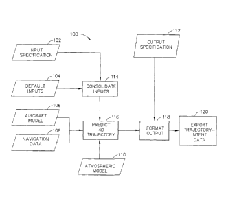
FIG. 1 is a data flow diagram of a trajectory-intent generation system 100 in
accordance
with an exemplary embodiment of the present invention. In the exemplary
embodiment,
trajectory-intent generation system 100 is configured to generate and export
trajectory-
intent data. Trajectory data describes the position of an aircraft or other
aerial vehicle in
4-dimensions for all positions of the aircraft between takeoff and landing.
The intent data
describes how the aircraft or other aerial vehicle will be flying along the
trajectory.
Trajectory-intent generation system 100 includes an input specification module
102 that
includes information specifying flight-specific input data used to generate
the trajectory.
The input specification information includes, for example, but not limited to,
aircraft type
(for example, Boeing 737-700 with Winglets and engines with 24 klbs thrust
rating),
Zero-Fuel Weight, Fuel, Cruise Altitude, Cost Index, and lateral route (such
as a city-pair
or airline preferred company route) and terminal procedures such as departure,
arrival,
and approach procedures. In the exemplary embodiment, the input specification
information is specific to a particular aircraft, which may be specified by a
tail number,
registration identifier, or other identifier of a particular aircraft.
Aircraft aerodynamics
and aircraft component (including engines) performance may change over time.
The
input specification information captures such changes and permits trajectory-
intent
generation system 100 to account for those differences in predicting the 4D
trajectory.
The input specification information is stored for example, in a file,
database, or data
structure (using a programming language such as MATLAB or C++) and may be
generated by a front-end graphical user interface.
Trajectory-intent generation system 100 also includes a default input module
104. The
default input information includes default values for inputs that are not
included in input
specification module 102. For example, in the weeks before a flight the exact
aircraft
type, gross weight and cost index may not be decided yet as they are
parameters that are
very dependant on weather and passenger count, which is likely not known well
enough
until right before flight. The aerial vehicle operator may specify default
values for these
parameters if they are not yet specified. A plurality of default value
combinations may be
CA 02772482 2012-03-22
248036
provided by the default input model 104 to capture various operational
scenarios such as
maximum takeoff, or ferry flight scenarios.
An aircraft model module 106 includes data that specifies the performance of
the aircraft
and engines. It is used by trajectory-intent generation system 100 to compute
the speeds,
thrust, drag, fuel-flow, and other characteristics of the aircraft needed to
predict the 4-
dimensional trajectory. In one embodiment, a publicly available performance
model such
as Eurocontrol's Base of Aircraft Data (BADA) may be used. Alternatively, the
trajectory predictor may use the aircraft and engine manufacturers proprietary
performance model, for example, an FMS-loadable Model-Engine Database or the
performance engineering data (provided in tabular format or embedded in flight
performance tools),. Further, the trajectory predictor may use the flight
performance data
in the Flight Crew Operations Manual which provides takeoff, climb, cruise,
descent,
approach operational performance data but not aircraft aerodynamic data and
engine
performance data.
A navigation data module 108 specifies the information needed to translate the
flight plan
into a series of latitudes, longitudes, altitudes and speeds used by
trajectory-intent
generation system 100 to generate a trajectory. In the exemplary embodiment,
navigation
data module 108 includes the same navigation database that is loaded into the
aircraft's
flight management system. In various embodiments, other navigation databases
are used
in navigation data module 108.
An atmospheric model module 110 includes data that describes the atmospheric
conditions for the flight, such as the standard atmospheric model and specific
weather
conditions including winds and temperatures aloft and air pressure. The
specific weather
data may be as simple as the average wind. Alternatively, it may be a gridded
data file
with conditions specified at various latitudes, longitudes, altitudes and
times (such as the
Rapid Update Cycle [RUC] data provided by the National Oceanic and Atmospheric
Association [NOAA]). Since this information may not be well known long before
the
6
CA 02772482 2012-03-22
248036
flight, this may also be historical statistical data such as mean winds, or
categorical data
such as hot summer day from which a more detailed model may be derived.
An output specification module 112 specifies the content and formatting for
the output of
the trajectory-intent data. Providing a flexible output format and content
allows only the
information necessary for the intended user to be provided. This allows
parameters such
as weight and cost index, which may be considered proprietary or competitively
sensitive
to the airline, to be hidden from users for which it is not needed. This also
allows the
content of the data to be tailored for its use. Long before the flight only a
small amount
of data related to the flight may be useful. This allows a reduction of the
file size to only
that necessary, thereby reducing communication costs.
Trajectory-intent generation system 100 also includes a consolidate inputs
module 114,
which is used to combine the specified inputs from input specification module
102 and
default inputs from default input module 104 into a consistent set of data. In
various
embodiments, consolidate inputs module 114 also performs a reasonableness
check to
ensure that specified inputs are within realistic bounds.
A predict 4D trajectory module 116 processes the specified inputs from input
specification module 102, default inputs from default input module 104,
aircraft
performance model from aircraft model module 106, navigation data from
navigation
data module 108, and weather information from atmospheric model module 110 to
generate a 4D trajectory for the specified flight. In various embodiments,
predict 4D
trajectory module 116 may be embodied in a Flight Management System Trajectory
Predictor, which would allow the full specification of flight inputs as is
available on the
aircraft itself.
A format output module 118 processes the trajectory and intent data and
converts it into
the format specified in output specification module 112. For example, this may
be a file
in Extensible Markup Language (XML) format, a simple ASCII text file, or a
data
structure in a language such at MATLAB or C++.
7
CA 02772482 2012-03-22
248036
An export trajectory-intent module 120 distributes the trajectory-intent
output from the
formatting process in format output module 118. In one embodiment, export
trajectory-
intent module 120 writes an output file. In various embodiments, export
trajectory-intent
module 120 writes output to, for example, but not limited to a TCP/IP network
connection. In one embodiment, a portion of the output file is transmitted to
the aircraft
as instructions for changing an onboard trajectory being used to operate the
aircraft via
wired or wireless data link.
Trajectory-intent generation system 100 permits sharing a wide range of
customized
trajectory and intent information for a specific flight or flights from an
aircraft operator to
an air navigation service provider (ANSP). The trajectory and intent
information can be
used to plan the demand for certain resources (such as an airspace sector or
airport
runway) and allocate staffing or resources by the ANSP. It can also be used as
the basis
for negotiating modifications to that trajectory in the form of new inputs.
For example, if
the proposed trajectory will violate a no-fly zone (such as a military Special
Use Airspace
that becomes active), this can be communicated to the aircraft operator and
new inputs to
generate a modified trajectory can be specified by the operator.
FIG. 2 is a data flow diagram of a trajectory dissemination and evaluation
system 200
such as another embodiment of trajectory-intent generation system 100 (shown
in FIG. 1)
in accordance with an exemplary embodiment of the present invention. In the
exemplary
embodiment, trajectory dissemination and evaluation system 200 is also used by
the
aircraft operator itself to evaluate the trajectory against operator
objectives, such as time
and fuel used, to modify the inputs to create a new trajectory. For example,
the cost
index or cruise altitude may be modified if the time and fuel cost do not
satisfy operator
business objectives. A first portion 202 of trajectory dissemination and
evaluation system
200 is used by an aircraft operator, such as, an airline company and includes
a flight input
module 204 configured to receive parameters for a flight that the operator
wants to
evaluate. The parameters are used to generate a 4D trajectory in a generate 4D
trajectory
module 206, such as that shown in FIG. 1. The generated 4D trajectory is
output to an
operator evaluate 4D trajectory module 207 of the first portion 202 of
trajectory
8
CA 02772482 2012-03-22
248036
dissemination and evaluation system 200 and to an ANSP evaluate 4D trajectory
module
210 of a second portion 212 of trajectory dissemination and evaluation system
200.
Operator evaluate 4D trajectory module 207 evaluates the generated 4D
trajectory for
compliance with the aircraft operator business goals or tests against various
operational
scenarios. The modify inputs module 208 of first portion 202 takes the output
from this
evaluation and in one embodiment, automatically adjusts the flight inputs
until the
aircraft operator business goals are met. In various other embodiments, modify
inputs
module 208 suggests changes to input parameters for evaluation and acceptance
by the
aircraft operator. The 4D trajectory may output to a display 216 or to other
systems (not
shown in FIG. 2) for further processing.
ANSP evaluate 4D trajectory module 210 is configured to receive and evaluate
the
generated 4D trajectory for compliance with the air navigation service
providers'
requirements. If the generated 4D trajectory does not meet the requirements of
the air
navigation service provider, the air navigation service provider can propose
changes to
the 4D trajectory through a propose modifications module 214 of second portion
212.
FIG. 3 is a data flow diagram for a group or cluster of Remote Trajectory
Management
Systems (RTMS) 300 in accordance with an exemplary embodiment of the present
invention. In the exemplary embodiment, RTMS cluster 300 is a tool that may be
embodied in for example, but not limited to, software, firmware, and/or
hardware. In the
exemplary embodiment, RTMS 300 includes a processor 301 communicatively
coupled
to a memory device 303 that is used to store instructions used by processor to
implement
RIMS 300. RIMS 300 provides a method for remotely managing the trajectory of a
manned or unmanned Aerial Vehicle (UAV) 302 to plan, modify, predict, and
manage an
aerial vehicle's trajectory in four-dimensional (4D) airspace. In the
exemplary
embodiment, RIMS 300 is installed in a Fleet Wide Trajectory Management System
304
at an aerial vehicle operator's Operations Control Center (OCC) that is
conveniently
accessible, directly or via wired or wireless network. FWTMS 304 is positioned
at a
location that is safe, economical, and effective for managing the trajectory,
which may
9
CA 02772482 2012-03-22
248036
either be a building structure, a ground vehicle, a sea borne vessel, another
aerial vehicle,
or a spacecraft.
RTMS 300 combines accurate trajectory planning and prediction capabilities in
an
FWTMS 304 at the OCC, incorporating information about the airspace
constraints,
strategic conflict resolution actions, and Traffic Flow Management (TFM)
initiatives
from an Air Navigation Service Provider (ANSP) 306 such as the Federal
Aviation
Administration (FAA) in the United States to achieve an optimal trajectory.
Trajectory
synchronization and negotiation between RTMS 300 and ANSP 306 are achieved
without
frequent costly (both in terms of monetary cost and time) wireless data link
communications between aerial vehicle 302 and ANSP 306, and frequent aircrew
responses in case of a manned aerial vehicle, during trajectory
synchronization and
negotiation. The final inputs that are sent to aerial vehicle 302, such as a
change in
altitude or several additional waypoints, are much more compact in size than
the entire
trajectory and thus significantly reduce costs for communication directly with
aerial
vehicle 302. The negotiated trajectory satisfies Air Traffic Control (ATC)
objectives, and
at the same time satisfies to a maximum the aerial vehicle operator's business
preference.
As a result, significant amount of fuel and flight time may be saved for the
operator, and
consequently reducing emissions to the atmosphere. For ANSP 306, the
negotiated
trajectories significantly increase system wide traffic throughput and
efficiency. A Fleet
Wide Trajectory Management System (FWTMS) 308 utilizing this method is built
to
manage trajectories for the entire fleet for an operator. The FWTMS 308 is a
system
consisting of a plurality of RTMS's 300 for individual aircraft in the
operator's fleet. The
system 308 can be integrated with other systems, such as the flight dispatch
system, the
flight performance engineering system, fuel planning systems, the aircrew
management
system, and the scheduling management system to improve the operator's
operations to
improve business bottom lines and customer satisfaction. FWTMS 308 may also be
configured to execute using processor 301 or may be embodied in a separate
processor
(not shown in FIG. 3).
CA 02772482 2012-03-22
248036
RTMS 300 embodies a method and system for managing the trajectory remotely for
aerial vehicle 302 using, in the exemplary embodiment, ANSP 306 and OCC 304.
ANSP
306 is the ground-based system and services that manage all air traffic in the
airspace.
The core of ANSP 306 is an automation system 310, which hosts a plurality of
Air
Traffic Management (ATM) 312 applications, air traffic controllers 314, and
air traffic
displays 316 used by air traffic controllers 314. ANSP 306 includes a Flight
Plan Filing
Interface 318 that receives flight plans 320 filed by OCC 304 through an OCC
Flight Plan
Filing Interface 322. ANSP 306 also includes an Air-Ground Data Link Manager
324
that supports a data link with aerial vehicle 302 and network communications
with OCC
304. Voice communication 326 is also available for tactical communications
between air
traffic controllers 314 and a pilot 328 for a manned aerial vehicle 302. For
an unmanned
aerial vehicle 302, ground operation control personnel handle the voice
communication
via interface to the voice channel of unmanned aerial vehicle 302 while the
voice
communication remains transparent to air traffic controllers 314.
Aerial vehicle 302 may be manned, such as but not limited to a commercial jet
airplane,
or unmanned. Aerial vehicle 302 may include a Flight Management System (FMS)
330,
which builds a trajectory for use by the aircraft's Automatic Flight Control
System
(AFCS) 332. There are a plurality of potential data link interfaces from the
ground to the
aircraft, including one from ANSP 306 (such as Aeronautical Telecommunication
Network [ATN]/VHF Datalink Mode 2 [VDL-2]) 334 and another from an OCC data
link
interface 336, such as Aircraft Communications Addressing and Reporting System
(ACARS).
OCC 304 is the facility that controls all aircraft for a given operator. OCC
304 may be
ground-, sea-, air-, or space-based, depending on the specific situation. A
novel aspect of
OCC 304 is FWTMS 308. FWTMS 308 includes one or more RTMSs 300. In the
exemplary embodiment, a single RTMS 300 generates a unique trajectory for each
aerial
vehicle 302 in the fleet. In various embodiments, a separate RTMS 300 is used
for each
aerial vehicle 302. In still other embodiments there may be multiple RTMSs
300, where
each one generates the trajectory for multiple aerial vehicles 302. The
implementation
11
CA 02772482 2012-03-22
248036
depends on processing speed needs and the interconnections between different
systems at
OCC 304, and the types of aircraft involved. RTMS 300 may include trajectory
management functionalities similar to those of FMS 330 but without the memory
and
computational power limitations of an airborne FMS 330.
In various embodiments, FWTMS 308 is used for Trajectory Synchronization and
Negotiation and OCC Flight Monitoring and Support.
The use of FWTMS 308 at OCC 304 for synchronization and negotiation of aerial
vehicle
302 trajectory reduces the bandwidth and data communication costs to aerial
vehicle 302,
because the cost of communicating with aerial vehicle 302 over ACARS and/or
ATN/VDL-2 are orders of magnitude larger than communications costs from OCC
304 to
ANSP 306, which could simply be via a secure TCP/IP connection. With FWTMS
308,
RTMS 300 for a specific aerial vehicle 302 may perform the trajectory
synchronization
and negotiation on behalf of the airborne FMS 330. RTMS 300 generates a
continuous
trajectory that is consistent with the airborne FMS (rather than simply a
sequence of
waypoints or airways that is generated by current flight planning systems),
and easily
accesses the latest weather forecast information. A state of aerial vehicle
302 (such as
weight), including meteorological parameters (current winds and temperature)
may be
provided by surveillance data (such as Radar or Automatic Dependent
Surveillance-
Broadcast [ADS-B]) or measured by airborne sensors and downlinked to RTMS 300
automatically when needed without pilot intervention, such as the existing
ACARS
meteorological reports. The operator-ANSP network employs a network layer that
is
much cheaper to operate and less congested than the air-ground data link thus
saves cost
for ANSP 306 and the operator of aerial vehicle 302. Only the modifications
needed by
the airborne FMS are uplinked to aerial vehicle 302 for pilot 328 to review
and accept. In
a final uplink, updated FMS weather can be an integrated part of the uplinked
data from
OCC 304. The trajectory determined by RTMS 300 stays synchronized with the FMS
trajectory throughout the duration of the flight to improve situation
awareness at OCC
304. With this operational concept, an UAV is no longer distinguishable from
manned
aircraft from the trajectory point of view.
12
CA 02772482 2012-03-22
248036
The OCC-based trajectory synchronization and negotiation, on the other hand,
would not
prevent direct air-ground exchange with ANSP 306 for short-term, tactical
trajectory
synchronization for conflict resolution or any other ATC actions which are
time-critical.
In various other embodiments, FWTMS 308 is used for OCC Flight Monitoring and
Support.
A major function of OCC 304 is to follow flights of a plurality of aerial
vehicles 302 and
provide flight information and technical support to the flights during their
execution. In
current operations, the flight monitoring system in OCC mainly utilizes
tracking
information provided by ANSP 306, such as FAA's Aircraft Situation Display to
Industry
(ASDI) system data. Some operators also include ACARS position reports
downlinked
by their flights in the flight monitoring system. However, FMS trajectories
are often not
accessible outside of aerial vehicle 302 or are expensive to communicate to
the ground
(to either OCC 304 or ANSP 306). This has resulted in poor predictions of the
Estimated
Time of Arrival (ETA), and thus has caused difficulties in planning ground
operations at
the destination airport. FWTMS 308 provides improved 4D trajectory prediction
capability for an entire fleet being hosted at a single facility, provides
data otherwise
unavailable and/or reducing communication costs. A number of individual aerial
vehicles 302 are assigned to an individual OCC controller (or dispatcher). The
trajectory
output may be shared with different systems at OCC 304 or different dispatcher
positions,
and the format of the trajectory may be formatted uniquely for each user. The
OCC
controller uses a graphical interface to monitor and interact with the
operations of RTMS
300 as if a remote cockpit is provided to the OCC controller and provides a
new means
for the operator's OCC 304 to communicate with aircrew in case of an
emergency, and
thus greatly enhance operational efficiency and safety.
RTMS 300 and FWTMS 308 provide the aerial vehicle operator the same level of
trajectory planning and prediction capability that previously was only
available onboard
aerial vehicle 302. Combined with direct knowledge of the aerial vehicle
trajectory, and
the capability of data link based trajectory synchronization and negotiation
with ANSP
13
CA 02772482 2012-03-22
248036
306, FWTMS 308 enables an operator to greatly improve their operations. This
could
result in significant fuel savings, flight delay reductions, reductions in
missed equipment
(e.g. aircraft) and crew connections, and consequently economic, social, and
environmental benefits. FWTMS 308 is able to manage trajectories for UAVs as
well,
and serves as a means to integrate UAVs in civilian airspace.
FIG. 4 is a flow diagram of a method 400 of managing an aerial vehicle
trajectory. In the
exemplary embodiment, method 400 includes receiving 402 by a remote trajectory
management system (RTMS) business information relating to the operation of the
aerial
vehicle from an operator entity of the aerial vehicle, negotiating 404 by the
RTMS
between the operator entity and the control entity a four-dimensional
trajectory for the
aerial vehicle, and transmitting 406 by the RTMS one or more trajectory
parameters that
facilitate the aerial vehicle complying with the negotiated trajectory to the
aerial vehicle.
The business information relating to the operation of the aerial vehicle can
include flight
planning information negotiated between the operator entity and an Air
Navigation
Service Provider (ANSP). The RTMS can also receive information relating to
airspace
constraints along a predetermined route of the aerial vehicle from an airspace
control
entity and weather information.
Method 400 also includes synchronizing the trajectory between the operator
entity and
the control entity wherein the trajectory may be a four-dimensional trajectory
for the
aerial vehicle. In various embodiments, the operator entity and the control
entity
synchronize the four-dimensional trajectory for the aerial vehicle by
exchanging
trajectory prediction and flight plan information. Exchanging trajectory
prediction and
flight plan information may also be a part of negotiating 404 by the RTMS
between the
operator entity and the control entity the 4D trajectory for the aerial
vehicle.
Method 400 also includes receiving from the control entity flight plan
modification data
that in some embodiments includes receiving one or more waypoints, at least
one of a
two-dimensional position and a time, and at least one of a two-dimensional
route change,
an altitude change, a speed change, and a required-time-of-arrival (RTA).
Method 400
14
CA 02772482 2012-03-22
248036
also includes transmitting to the control entity a business preferred
trajectory including at
least one of an end-to-end two-dimensional route, a portion of a two-
dimensional route, a
cruise altitude, a departure procedure, an arrival procedure, and a preferred
runway. The
business preferred trajectory may be based on at least one of a RTMS predicted
trajectory, and a RTMS predicted trajectory based on information obtained from
the
control entity. The one or more waypoints may include a three-dimensional
position and
a required time-of-arrival (RTA) at the three-dimensional position.
In an embodiment, method 400 includes receiving from the aerial vehicle a
state of the
aerial vehicle. The state may include at least one of a weight of the aerial
vehicle,
parameters measured by airborne sensors, and at least one of 3D and 4D
position data,
and meteorological parameters in a vicinity of the aerial vehicle. Method may
also
include transmitting to the aerial vehicle one or more waypoints to a flight
management
system (FMS) of the aerial vehicle.
The term processor, as used herein, refers to central processing units,
microprocessors,
microcontrollers, reduced instruction set circuits (RISC), application
specific integrated
circuits (ASIC), logic circuits, virtual machines, and any other circuit or
processor
capable of executing the functions described herein.
As used herein, the terms "software" and "firmware" are interchangeable, and
include
any computer program stored in memory for execution by processor 301,
including RAM
memory, ROM memory, EPROM memory, EEPROM memory, and non-volatile RAM
(NVRAM) memory. The above memory types are exemplary only, and are thus not
limiting as to the types of memory usable for storage of a computer program.
As will be appreciated based on the foregoing specification, the above-
described
embodiments of the disclosure may be implemented using computer programming or
engineering techniques including computer software, firmware, hardware or any
combination or subset thereof, wherein the technical effect is for providing
4D trajectory
support for an aerial vehicle while maintaining a reduced computational load
and
communications burden on the aerial vehicle onboard systems. By receiving
information
CA 02772482 2012-03-22
248036
from the aerial vehicle unavailable otherwise and transmitting only updates to
the 4D
trajectory carried onboard the aerial vehicle a robust, accurate, and timely
4D trajectory
can be maintained. The system manages negotiations with regulatory bodies to
generate
the 4D trajectory that satisfies the aerial vehicle operator's business plan
as well as
efficient and safe throughput of a plurality of other aerial vehicles under
the jurisdiction
of the regulatory body. Any such resulting program, having computer-readable
code
means, may be embodied or provided within one or more computer-readable media,
thereby making a computer program product, i.e., an article of manufacture,
according to
the discussed embodiments of the disclosure. The computer-readable media may
be, for
example, but is not limited to, a fixed (hard) drive, diskette, optical disk,
magnetic tape,
semiconductor memory such as read-only memory (ROM), and/or any
transmitting/receiving medium such as the Internet or other communication
network or
link. The article of manufacture containing the computer code may be made
and/or used
by executing the code directly from one medium, by copying the code from one
medium
to another medium, or by transmitting the code over a network.
The above-described embodiments of a method and system of generating a 4D
trajectory
for an aerial vehicle provides a cost-effective and reliable means for sharing
the trajectory
and intent information of an aerial vehicle operator in a strategic manner,
improving the
ability to plan the flight and allocate appropriate resources to it. More
specifically, the
methods and systems described herein facilitate accurate generation of the
trajectory and
intent data, customizable trajectory output format, flexible input methods,
and fast
processing and dissemination of the relevant information. Additional
advantages of the
method and system described herein include improved collaboration and
information
sharing between aircraft operators and ANSPs, planning of flight trajectories
for
operators, which can reduce costs, and simple and inexpensive operation using
for
example, but not limited to, a stand alone personal computer. As a result, the
methods
and systems described herein facilitate automatically managing a 4D trajectory
of an
aerial vehicle in a cost-effective and reliable manner.
16
CA 02772482 2012-03-22
248036
An exemplary method and system for automatically, or semi-automatically
managing 4D
trajectories for a single or a plurality of aerial vehicles are described
above in detail. The
system illustrated is not limited to the specific embodiments described
herein, but rather,
components of each may be utilized independently and separately from other
components
described herein. Each system component can also be used in combination with
other
system components.
This written description uses examples to disclose the invention, including
the best mode,
and also to enable any person skilled in the art to practice the invention,
including making
and using any devices or systems and performing any incorporated methods. The
patentable scope of the invention is defined by the claims, and may include
other
examples that occur to those skilled in the art. Such other examples are
intended to be
within the scope of the claims if they have structural elements that do not
differ from the
literal language of the claims, or if they include equivalent structural
elements with
insubstantial differences from the literal languages of the claims.
17