Note: Descriptions are shown in the official language in which they were submitted.
CA 02776034 2012-03-29
1
AIRCRAFT RING FRAME AND METHOD FOR OBTAINING IT
FIELD OF THE INVENTION
This invention refers to a new design of aircraft frames in a composite
material,
specifically for fuselages integrated into a single piece, as well as to a
method for
obtaining them.
BACKGROUND OF THE INVENTION
The fuselage is the main assembly of an aircraft, given that the remaining
elements that make up the aircraft are directly or indirectly joined to it.
The skin of the
fuselage is what gives it its shape, which varies with the main mission that
the aircraft
will have.
In addition to the skin (the one being considered is CFRP - Carbon Fiber
Reinforced Plastic), the fuselage of an aircraft comprises some elements in
the shape
of perpendicular framework with respect to the lengthwise axis of the
aircraft, called
frames (made of CFRP or metal, in the shape of a C, Z, etc.), which are
responsible for
giving shape and rigidity to the fuselage structure, with these frames being
located at
given intervals on the inside of the aircraft fuselage. In addition to the
frames, the
fuselage comprises other reinforcement elements, such as the stringers
(generally in
an omega shape, T or similar) to achieve optimization of load distribution and
rigidity.
The stringers are located lengthwise on the fuselage skin, allowing the
optimization of
the same, thus lightening the weight of the combined structure. In this
manner, the
entire grid of frames, stringers and skin are joined together to form a
complete
structure.
Traditionally, the fuselage of an aircraft was built-up in a segmented way, so
that the skin was formed by several panels and sections which were later
joined to form
the typical fuselage in a cylindrical shape. The joints between these segments
or
panels were embodied through a series of joining parts designed for this
purpose,
which generally were joined with fasteners . The frames in the case of these
fuselages
were adjusted manually on the previous structure. This procedure of
arrangement and
placing the frames is an easy assembly, since the parts that make up the
fuselage skin
are opened on the inside, in such a manner that it allows a simple and correct
adjustment of the frames, by segments. However, this procedure forces a very
high
number of segments or partitions of the frames, which involves also having to
use a
large number of joining parts between the frames and the skin that make up the
CA 02776034 2012-03-29
2
fuselage. This causes the procedure of assembling the frames to be very long
and
expensive, using a large amount of assembly labor.
Today, it is becoming increasingly common the manufacturing of the skin that
makes up the fuselage of an aircraft to be obtain in one whole piece, called
3600, full-
barrel or one-shot fuselage. The skin that forms the fuselage is formed
integrally into a
single closed piece from a single mould. With these integral skins, the
segmenting of
frames has to be approached differently from the segmenting used until now, as
it's
necessary to pay attention to the difference tolerances that are involved in
the
manufacturing and assembly processes and also to access limitations for the
arrangement of these segmented frames.
The present invention offers a solution to the aforementioned limitations.
SUMMARY OF THE INVENTION
Thus, according to a first aspect, this invention refers to a new design of
aircraft
frames made of composite material, those frames being made in partitions or
segments
with a determined length, which will be arranged on the interior of the skin
that forms
the aircraft fuselage. The fuselage will be integrally manufactured in a
single piece
(called full-barrel or one-shot fuselage). This fuselage may comprise
integrated
stringers from the same manufacturing process of the aforementioned fuselage.
The
length of the partitions or segments of the frames will be the maximum
possible (which
will lead to the minimum number of partitions per diameter of fuselage
section), so that
the maximum gap between these frame segments and the skin, with this gap being
measured from the interior of the skin, allows the use of a liquid sealant for
joining the
frame segment to the skin. The use of this type of sealant simplifies the
operations and
decreases the assembly times, which allows recurring costs to decrease in this
regard.
The maximum length of the frame segments will be calculated based upon the
manufacturing limitations given by the manufacturing tolerances of the skin
and of the
same frame segments.
Furthermore, in the design of the partitions or segments of these frames, the
following considerations must be taken into account:
- contraction or spring-back effect during the manufacturing of the frame
elements;
- assembly process of the frame partitions or segments;
- geometry of the fuselage section, given by the skin, where the frame
CA 02776034 2012-03-29
3
partition or segment will be arranged;
the loads to which the fuselage section is subject, given by the skin, where
the frame partition or segment will be arranged.
According to a second aspect, the invention refers to a method for obtaining
the
design of aircraft frames, which are made of composite material, and
comprising
partitions or segments of a given length, in such a manner that the calculated
frame
segments maintain a maximum separation with respect to the interior of the
skin, which
is such that it will allow the use of a liquid sealant for joining the frame
segment to the
skin that forms the fuselage.
Thus, the method of the invention comprises the following stages:
a) determining a first frame type segment for the upper part of the fuselage
skin, for a given section of the fuselage, with this being calculated for the
case where the aerodynamic tolerance on the skin causes this to have a
maximum effective external dimension, with the thickness tolerance of
the skin being as low as possible, in such a way that the inside
dimension of the skin is maximum and the manufacturing tolerance of
this frame segment is minimal, which causes the dimension of the frame
segment to be minimal;
b) determining the point of contact of the frame type segment with the
inside of the skin as a result of stage a);
c) determining the frame segment points on both sides of the previous
contact point, where the maximum separation between the frame
segment and the inside of the skin is the maximum permitted for the use
of a liquid type sealant;
d) calculating the length of the maximum frame segment as per stages a)
to c) above, and such that the ends of the frame segment are arranged
at halfway of a span between two consecutive stringers of the section;
e) repeating stages a) to d) above for the remaining segments that will
form the partitions of the frame in its entirety;
f) determining a second frame type segment for the upper part of the
fuselage skin, for the aforementioned given section of the fuselage, with
this being calculated for the case where the aerodynamic tolerance on
CA 02776034 2012-03-29
4
the skin causes this to have a minimum effective external dimension,
with the thickness tolerance of the skin being the maximum possible, in
such a way that the inside dimension of the skin is minimal and the
manufacturing tolerance of this frame segment is a maximum, which
causes the dimension of the aforementioned frame segment to be the
maximum;
g) determining the points of contact of the frame type segment with the
inside of the skin as a result of stage f);
h) determining the frame segment point on which the maximum separation
between the frame segment and the inside of the skin is the maximum
permitted for the use of a liquid type sealant;
i) calculating the length of the maximum frame segment as per stages f) to
h) above, and such that the ends of the frame segment are arranged at
halfway of a span between two consecutive stringers of the section;
j) repeating stages f) to i) above for the remaining segments that will form
the partitions of the frame in its entirety;
k) determining the definitive frame segments, such that said segments
verify both stages a) to d) and stages f) to j) as cited above, with the
segments forming the definitive partitions of the entirety of the frames,
for the specific calculated fuselage section;
I) determining the fuselage frame segments for each specific fuselage
section, following stages a) to k) above.
Other characteristics and advantages of this invention will come from the
detailed description that follows of an embodiment illustrating its purpose in
relation to the attached figures.
DESCRIPTION OF THE FIGURES
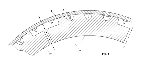
Figure 1 shows in a section a breakdown of an aircraft fuselage that comprises
an aircraft fuselage design as per this invention.
Figure 2 shows in a section the tolerances that are taken into consideration
for
the design of the aircraft frames as per this invention.
Figure 3 shows in a section the case where the manufacturing tolerances that
are taken into consideration for the design of the aircraft frame as per the
method of
CA 02776034 2012-03-29
this invention, converge so that the manufactured frame is at its smaller size
than its
nominal value, with the fuselage skin being manufactured at its larger size
and lower
thickness than its respective nominal values.
Figure 4 shows in a section the case where the manufacturing tolerances that
5 are taken into consideration for the design of the aircraft frame as per the
method of
this invention, converge so that the manufactured frame is a larger size than
its
nominal value, with the fuselage skin being manufactured in a smaller size and
greater
thickness than its respective nominal values.
DETAILED DESCRIPTION OF THE INVENTION
Thus, this invention refers to the new design of aircraft frames made of
composite material, which are being made in partitions or segments 1 with a
determined length 2, which will be arranged on the interior of the skin 3 that
forms the
aircraft fuselage. The fuselage will be manufactured in a single piece (called
full-barrel
or one-shot fuselage), so that the length 2 of the partitions or segments 1 of
the
aforementioned frames will be the maximum possible (which will lead to the
minimum
number of partitions 1 per diameter of fuselage section), so that the maximum
gap 5
between each frame section 1 and the skin 3, with this distance or gap 5 being
measured by the interior of the fuselage, is lower than the permitted limit
for the
application of a liquid sealant. This maximum gap 5 will be calculated based
upon the
manufacturing limitations given by the manufacturing tolerances of skin 3 and
of the
frames. Typically, the value of maximum gap 5 for the application of a liquid
sealant is
around 0.5 mm. Another type of sealant must be applied when above this
separation
value 5 (typically solid sealant), which increases the assembly times and
decreases the
mechanical properties of the assembly.
Furthermore, the design of the partitions 20 in segments 1 of the
aforementioned frames, as per the invention, is also determined on the basis
of:
contraction or spring-back effect of sections 1 of the frame during the
manufacturing of the frame sections 1;
assembly process of the frame sections 1 in its partitions 20, taking into
consideration that the access for this assembly process is limited, since the
skin of the fuselage is manufactured integrally in one part (full-barrel or
one-
shot);
- geometry of the fuselage section where section 1 of the frame is arranged,
CA 02776034 2012-03-29
6
specifically the curvature of the same;
the loads to which the fuselage section is subject, where section 1 of the
frame is arranged, avoiding where possible embodying the partition or
section 1 of the frame in an area or section of fuselage that is subject to a
very high load.
In this manner, and based upon the foregoing, the length 2 of the frame
section
1 will be such that the lowest possible number of sections 1 or partitions 20
will be
obtained, i.e. the length 2 will be the highest possible. In this manner
savings are
achieved in the number of joining parts and elements used in the traditional
designs, as
well as in assembly time, by avoiding the use of sealants in a solid state,
which leads to
savings in assembly time and labor, thus avoiding problems in the riveting
operation,
without this involving a loss of mechanical characteristics of the joint.
Taking into consideration the manufacturing tolerances of skin 3 (aerodynamic
tolerance that causes skin 3 to have an effective external value of 11 and
thickness
tolerance of the skin 3 that causes the skin 3 to have an effective internal
value of 12)
and of frame section 1 (manufacturing tolerance of frame section 1, which
causes the
aforementioned frame to have an effective external value of 13), as well as
the
limitations imposed by the maximum admissible gap 5 in assembly under which it
is
possible to apply liquid sealant, the number and optimal position of frame
sections 1 of
the invention are defined, i.e. the number of partitions 20 of which the
complete frame
of the invention is composed.
Two extreme cases are considered for the calculation of the maximum length 2
of the partitions or segments 1 of the aforementioned frames, which will
determine the
number of partitions 20 of which the frame is composed in its entirety, based
upon the
calculation of the maximum gap 5. This is embodied by taking into
consideration the
manufacturing limitations given by the manufacturing tolerances of skin 3
(aerodynamic
tolerance that causes skin 3 to have an effective external value of 11 and
thickness
tolerance of the skin 3 that causes the skin 3 to have an effective internal
value of 12)
and of frame section 1 (manufacturing tolerance of frame section 1, which
causes the
aforementioned frame to have an effective external value of 13).
Case 1 (Figure 3):
- skin 3 is at its maximum size, since the aerodynamic tolerance is at its
maximum (effective external value 11 is the maximum) and its thickness
CA 02776034 2012-03-29
7
tolerance at its minimum (effective internal value 12 is the maximum);
- frame section 1 is at its minimum size, since the manufacturing tolerance of
the same is the minimum (effective external value 13 is the minimum);
- under the above conditions, the maximum gap 5 between the skin 3 and
frame section 1, for the case of cylindrical fuselage, appears close to the
ends 6 of the frame section 1 (Figure 3).
Case 2 (Figure 4):
- skin 3 is at its minimum size, since the aerodynamic tolerance of the same
is at its minimum (effective external value 11 is the minimum) and its
thickness tolerance the maximum (effective internal value 12 is the
minimum);
- frame section 1 is a maximum size, since the manufacturing tolerance of the
same is the maximum (effective external value 13 is the maximum);
- under the above conditions, the maximum gap 5 between the skin 3 and
frame section 1, for the case of cylindrical fuselage, appears in an area 7
close to the center of the frame section 1 (Figure 4).
Thus, based upon cases 1 and 2 mentioned above, the maximum gap 5 is
systematically obtained for each possible frame section 1, as per the
invention. Once
the areas are known in which the gap between skin 3 and the frame segments 1
is the
maximum and lower than the application limit of the defined liquid sealant,
and in
accordance with the remaining stated considerations, the frame partitions 20
are
defined between two consecutive stringers 4, independently of the fact that
the 4 are
already integrated from the same manufacturing process of the aforementioned
fuselage, or manufactured independently and then arranged on the aircraft
fuselage,
generally through rivets.
According to a second aspect, the invention develops a method for obtaining
these aircraft frames made of composite material, with those frames being
embodied in
partitions or segments 1 of a given length 2, which will be arranged on the
inside of
skin 3 that forms the aircraft fuselage. Thus, the method of the invention
comprises the
following stages:
a) determining a first frame type segment 1 for the upper part of the
fuselage skin 3, for a given section of the fuselage, with this first
CA 02776034 2012-03-29
8
segment 1 being calculated for the case where the aerodynamic
tolerance on the skin causes this to have a maximum effective external
dimension 11, with the thickness tolerance of the skin being as low as
possible, in such a way that the inside dimension of the skin 12 is
maximum and the manufacturing tolerance of this frame type segment is
minimal, which causes the dimension 13 of the aforementioned frame
segment 1 to be minimal;
b) determining the point of contact of the frame type segment 1 with the
inside of the skin 3 as a result of stage a);
c) determining the frame segment 1 points on both sides of the previous
contact point, where the maximum gap 5 between said frame segment 1
and the inside of the skin 3 is the maximum permitted for the use of a
liquid type sealant;
d) calculating the length 2 of the maximum frame segment 1 as per stages
a) to c) above, and such that the ends of the frame segment 1 are
arranged at halfway of a span between two consecutive 4 of the section;
e) repeating stages a) to d) above for the remaining segments 1 that will
form the partitions of the frame in its entirety;
f) determining a second frame type segment 1 for the upper part of the
fuselage skin 3, for the aforementioned given section of the fuselage,
with said second segment 1 being calculated for the case where the
aerodynamic tolerance on the skin causes this to have a minimum
effective external dimension 11, with the thickness tolerance of the skin
being the maximum possible, in such a way that the inside dimension of
the skin 12 is minimal and the manufacturing tolerance of this frame
segment is a maximum, which causes the dimension 13 of the
aforementioned frame segment 1 to be the maximum;
g) determining the points of contact of the frame type segment 1 with the
inside of the skin 3 as a result of stage f);
h) determining the frame segment point 1 on which the maximum
separation between said frame segment and the inside of the skin 3 is
the maximum permitted for the use of a liquid type sealant;
i) calculating the length 2 of the maximum frame segment 1 as per stages
CA 02776034 2012-03-29
9
f) to h) above, and such that the ends of the frame segment 1 are
arranged at halfway of a span between two consecutive 4 of the section;
j) repeating stages f) to i) above for the remaining segments 1 that will
form the partitions of the frame in its entirety;
k) determining the definitive frame segments 1, such that said segments 1
verify both stages a) to d) and stages f) to j) as cited above, with the
segments 1 forming the definitive partitions of the entirety of the frames,
for the specific calculated fuselage section;
I) determining the fuselage frame segments 1 for each specific fuselage
section, following stages a) to k) above.
For the best and fastest attainment of the method described above, it is
desirable to prepare tabulations to which one may turn for carrying out the
stages d),
e), i), j) and k) above. It is also possible to carry out stages d), e), i),
j) and k) above
through any computer calculation program.
The aircraft fuselage, and therefore the skin that forms the same can have a
cylindrical section, or a conical section. In addition, they can have certain
section
changes throughout their length, according to the lengthwise axis of the
aircraft. In any
of these cases, the method of the invention and the design of frames obtained
with the
same, are perfectly valid.
In the case where the fuselage, and therefore the skin 3 is cylindrical, in
the
above stage c), the points on which it occurs that the maximum gap 5 between
the skin
3 and frame segment 1 is such that it allows the use of liquid type sealant,
are found on
ends 6 of the calculated frame segment 1. For the case of stage h) above, the
point on
which the maximum gap 5 between the skin 3 and the frame section 1 appears, is
found in an area 7 close to the center of the frame section 1.
In the preferred embodiments that we have just described, those modifications
can be introduced that are included within the scope defined by the following
claims.