Note: Descriptions are shown in the official language in which they were submitted.
CA 02778040 2012-04-18
WO 2011/049637 PCT/US2010/030524
KNEE BALANCING FOR REVISION PROCEDURES
BACKGROUND OF THE INVENTION
[0001] The present invention relates generally to medical and surgical
devices, systems and
methods. More specifically, the invention relates to devices, systems and
methods for
enhancing knee surgery procedures, in particular, knee replacement procedures
and
specifically revision total knee replacement procedures.
[0002] The knee is generally defined as the point of articulation of the femur
with the tibia.
Structures that make up the knee include the distal femur, the proximal tibia,
the patella, and
the soft tissues, including ligaments, within and surrounding the knee joint.
The knee is
generally divided into three compartments: medial (the inside part of the
knee), lateral (the
outside part of the knee), and patellofemoral (the joint between the kneecap
and the femur).
The medial compartment comprises the medial joint surfaces of the femur,
tibia, and the
meniscus wedged therebetween. The lateral compartment comprises the lateral
joint surfaces
of the femur, tibia, and the meniscus wedged therebetween. The patellofemoral
compartment
comprises the joint between the undersurface of the kneecap or patella and the
femur. Four
ligaments are especially important in the stability, alignment and functioning
of the knee: 1)
the anterior cruciate ligament; 2) the posterior cruciate ligament; 3) the
medial collateral
ligament; and 4) the lateral collateral ligament. In an arthritic knee,
protective cartilage at the
point of articulation of the femur with the tibia is often worn away, allowing
the femur to
directly contact the tibia. This bone-on-bone contact can cause significant
pain, discomfort,
and disability for a patient and will often necessitate knee replacement or
knee arthroplasty.
[0003] Under certain circumstances, a previously implanted prosthetic knee
joint may need
to be replaced by a new prosthetic knee joint in a procedure called knee
revision surgery or
revision TKA. Common causes for needing revision TKA include; infection,
instability,
including specifically flexion instability, femoral component mal-rotation
causing poor
patellar tracking, and loosening of the prosthetic implants from the bone to
which they were
attached. Instability is often attributable to poor balancing of the soft
tissue during the index
or primary TKA.
[0004] Revision TKA procedures share some similarities with TKA procedures
with
respect to components being implanted, such as the prosthetic femur, tibia,
and patella. In
1
CA 02778040 2012-04-18
WO 2011/049637 PCT/US2010/030524
revision TKA, the old femoral component and tibial component of the prosthetic
knee joint
are most often removed. Removing the old prosthetic components can be very
time
consuming, and often large segments of bone may come off with the removed
prostheses. As
such, empirical landmarks that might otherwise be used to reference proper
balance and
position for the revision TKA femoral and tibial components are often
undistinguishable.
The quality of the femoral bone uncovered during revision TKA is often
severely
osteoporotic, lacking external structural integrity often due to stress
shielding caused by poor
balancing. Bone quality is enhanced by normal compressive stress forces,
conversely, bone
quality will deplete if the bone is shielded from those same stress forces.
[0005] Like with TKA, a challenge in revision TKA is to properly balance
ligament
tension, especially in the medial and lateral collateral ligaments, through a
full range of
motion of the knee, for example, from a fully extended to a fully flexed
position, or vice
versa. The collateral ligaments, which connect the distal femur and the
proximal tibia on the
medial and lateral aspects of the knee, account for much of the stability and
movement of the
knee. If one of the collateral ligaments is too lax or too tight relative to
the other collateral
ligament, the knee will typically be unstable, range of motion may be limited,
the patella may
track improperly, and/or the femur and tibia may wear unevenly, leading to
arthritis and pain
which may often necessitate another repeat surgery. Thus, it is imperative for
the short and
long-term success of a revision TKA procedure to achieve balanced ligament
tension in the
knee through a full range of motion.
[0006] Balancing ligament tension during any knee replacement surgery is
complicated by
the fact that the natural knee does not operate like a hinge moving about a
single axis. The
knee exhibits dynamic external rotation of the tibia relative to the femur as
the knee moves
from its flexed to its fully extended position. This automatic rotation of the
tibia occurs in the
opposite direction when the knee is flexed from its fully extended position to
produce an
internal rotation of the tibia relative to the femur. Thus, the natural knee
exhibits a rotary
laxity that allows the tibia to rotate through a limited internal and external
arc, during knee
flexion. Additionally, the femur translates anteriorly and posteriorly as the
tibia is being
flexed about the femur, bringing yet another movement variable. Thus, the
ligaments of the
knee, along with the femur, tibia and patella, create a dynamic bio-mechanism,
making
ligament tension balancing in knee replacement surgeries challenging. Many
articles and
studies have been devoted to ligament tension balancing in TKA, such as:
Mihalko, W.H. et
al., Comparison of Ligament-Balancing Techniques During Total Knee
Arthroplasty, Jnl.
2
CA 02778040 2012-04-18
WO 2011/049637 PCT/US2010/030524
Bone & Jt. Surg., Vol. 85-A, Supplement 4, 2003, 132-135; Eckhoff, D.G. et
al., Three-
Dimensional Morphology and Kinematics of the Distal Part of the Femur Viewed
in Virtual
Reality, Jnl. Bone & Jt. Surg., Vol. 85-A, Supplement 4, 2003, 97-104; and
Ries, M.D. et al.,
Soft-Tissue Balance in Revision Total Knee Arthroplasty, Jnl. Bone & Jt.
Surg., Vol. 85-A,
Supplement 4, 2003, 38-42.
[0007] Balancing a knee specifically during revision TKA is further
complicated by the
poor quality of bone often encountered and/or missing portions of the bone
itself. Balancing
techniques and instruments for balancing a knee during revision TKA often
reference from
the femoral intramedullary canal, specifically due to the fact the external
femoral bone
quality is not suitable for fixating balancing instruments. Additionally, the
femoral
intramedullary canal is often used to establish the anterior-posterior
location of the
replacement femoral component.
[0008] The components of a revision TKA femoral knee prosthesis may be
selected to have
specific sizes and to be specifically positioned to balance ligament tension.
Revision TKA
procedures may involve making further distal cuts across the distal end of the
femur, anterior
and posterior cuts, and angled anterior and posterior chamfer cuts to help
secure the femoral
component solidly in place. The surgeon attempts to make these femoral bone
cuts to
achieve a position and orientation of the femoral prosthetic component so as
to optimally
balance ligament tension through a full range of motion of the knee, and to
achieve balance
specifically of and between the flexion axis and the extension axis. However,
it is often very
challenging to position the femoral bone cuts and femoral prosthetic component
to provide
ideal ligament tension through the full range of motion of the knee. This is
due primarily to a
"trade-off' often facing the surgeon between optimal fixation vs. optimal soft-
tissue
balancing. Secure fixation is required, but if chosen at the expense of proper
balancing, there
is a distinct possibility the revision TKA will also fail for some of the same
reasons as the
primary knee including poor balancing leading to flexion instability and/or
stress shielding,
for example. The human femur has a natural bow or radius of approximately 70-
120cm
along its length. Due to the natural radius of the femur, placing a long
intermedullary rod up
the femoral intramedullary canal to establish the anterior-posterior (A-P)
location of the
femoral component often results in the rod skiving anteriorly as it is
inserted deep into the
femoral diaphysis while also shifting posteriorly outside the distal femur.
Locating off of this
rod, or establishing the A-P location of the femoral component off of the rod
in such a
3
CA 02778040 2012-04-18
WO 2011/049637 PCT/US2010/030524
skewed position, will compromise the balance of the knee between the flexion
axis and the
extension axis.
[0009] A number of devices and techniques have been described that attempt to
facilitate
ligament balancing during a TKA procedure. These devices and techniques may
also find
use for revision TKA procedures. Some techniques, such as those described in
U.S. Patent
No. 5,733,292, involve trial prosthesis components which are used after
femoral and tibial
bone cuts are made to assess ligament tension. Some devices, such as those
described in U.S.
Patent No. 6,758,850, are used to measure a gap between the distal femur and
proximal tibia
in extension and to help a surgeon recreate that same gap when the knee is in
flexion. Other
"gap checking" devices are described in U.S. Patent No. 6,575,980. Other
devices have been
developed to help measure an amount of ligament tension or to apply a desired
amount of
tension to the ligaments. U.S. Patent No. 4,501,266, for example, describes a
knee
distraction device for applying a desired amount of tension. Many paddle-like
devices have
been suggested for applying or measuring tension across a knee joint, such as
the devices
described in U.S. Patent Nos. 5,597,379; 5,540,696; 5,800,438; 5,860,980;
5,911,723; and
6,022,377. Other methods and devices include those described in co-assigned
U.S. Patent
Nos. 7,442,196, and 7,574,821, as well as co-assigned and co-pending U.S.
Application Nos.
11/149,944 (Attorney Docket No. 021976-000220US), 12/544,897 (Attorney Docket
No.
021976-00081 OUS, and 12/609,666 (Attorney Docket No. 021976-00091 OUS each of
which
are incorporated herein by reference.
[0010] Additional information relating to attempts to address the problems
described above
may be found in U.S. Patent Nos. 5,470,354; 5,656,785; 7,104,996 and U.S.
Patent
Application Publication Nos. 2005/0209605; 2005/0240196; 2005/0267485;
2006/0241569;
2007/0219559; 2007/0232959; and PCT Publication Nos. WO 2005/089681; WO
2005/037121; WO 2006/047005, for example. However, each one of these
references suffers
from one or more of the above-identified disadvantages.
[0011] For at least the above reasons, a need exists for improved devices,
systems and
methods for enhancing knee replacement surgery and specifically for
dynamically balancing
ligaments during knee replacement to improve range of motion, stability, and
patellar
tracking of the prosthetic knee joint. Additionally, such devices would allow
for secure
fixation to the femur via the intramedullary canal, without being biased by
the natural bow of
the femoral canal, and without the intramedularry canal dictating the balance
point of and
4
CA 02778040 2012-04-18
WO 2011/049637 PCT/US2010/030524
between the flexion axis and the extension axis of the femur. Ideally, such
devices and
methods would allow a surgeon to achieve a desired ligament tension balance
before
committing to and making final bone cuts to the femur. Such devices would
ideally be
simple to use in conjunction with existing knee replacement procedures and
equipment such
as prosthesis templates, measurement guides, cutting guides, and saw blades or
burs. At least
some of these objectives will be met by the present invention.
BRIEF SUMMARY OF THE INVENTION
[0012] Methods, systems and devices are provided for facilitating a surgical
procedure on a
knee, in particular, a revision total knee replacement procedure. Prior
femoral and at least a
portion of the tibial prostheses are removed. A cut end of a distal femur is
engaged with a
femoral adjustment member. The lateral force and the medial force exerted by
lateral and
medial sides of the femoral adjustment member and tibial prosthesis against
each other are
measured. The femoral adjustment member is adjusted to apply and/or adjust
tension to the
lateral collateral ligament and/or the medial collateral ligament based on the
measured forces,
for example, so that the measured forces are matched. Thus, the invention
provides a
quantifiable and repeatable measurement of forces caused by knee ligaments.
These
measurements can facilitate the balancing of knee ligaments during surgical
procedures on
the knee. Based on the position of the adjusted femoral member, guide cuts for
placement of
a new femoral prosthesis may be made on the cut end of the distal femur. The
new femoral
prosthesis will therefore be implanted and positioned such that the adjacent
knee ligaments
are well balanced.
[0013] In a first aspect, embodiments of the invention provide a method for
facilitating a
surgical procedure on a knee. An intermedullary rod is inserted into the
femoral
intermedullary canal of a femur. Once inserted into the canal, a portion of
the intermedullary
rod extends distally outward from a cut distal end of the femur. A femoral
adjustment
member is slid over this distally extending portion so as to engage the cut
distal end of the
femur with the femoral adjustment member. The femoral adjustment member
comprises a
lateral femoral portion and a medial femoral portion, and may also provide a
trochlear groove
femoral member. A lateral force exerted by the lateral femoral portion and a
lateral tibial
portion of a tibial plateau against one another is measured. A medial force
exerted by the
medial femoral portion and a medial tibial portion of the tibial plateau
against one another is
CA 02778040 2012-04-18
WO 2011/049637 PCT/US2010/030524
measured. The femoral adjustment member is then adjusted based on the measured
lateral
and medial forces to apply and/or adjust tension to the lateral collateral
ligament and/or the
medial collateral ligament. The femoral adjustment member may be adjusted so
that the
measured lateral force matches the medial force.
[0014] Typically, the femoral adjustment member is adapted to self-adjust to
allow for
positioning flush upon the face of the recut distal femur, without being
influenced by the
anterior-posterior insertion angle of the rod, when it is slid over the
distally extending portion
of the rod. The femoral adjustment member may position itself about the
intermedullary rod
while also maintaining moveable freedom to center itself about the rod. The
femur may be
rotated about the intermedullary rod, with the medial side of the femoral
adjustment member
as a balancing fulcrum.
[0015] The femoral adjustment member may be locked in a fixed position
relative to the
intermedullary rod, for example, by sliding a locking clamp over the distally
extending
portion of the intermedullary rod and tightening the locking clamp, or by
locking the femoral
adjustment member over a low-profile distally extending portion of the
intermedullary rod
via a short set screw or short cam lock screw. The trochlear groove femoral
member may be
integral to the adjustable femoral member, or removably attachable to the
adjustable femoral
member. Additionally, the trochlear groove femoral member may come in several
thicknesses to allow for gap balancing the extension gap to the flexion gap.
[0016] A force sensor may be used to measure the medial and/or lateral forces.
The force
sensor is inserted between the engaged femoral adjustment member and the
tibial plateau. A
lateral side of the force sensor is disposed between a lateral tibial portion
of the tibial plateau
and the lateral femoral portion of the femoral adjustment member. A medial
side of the force
sensor is disposed between a medial tibial portion of the tibial plateau and
the medial femoral
portion of the femoral adjustment member. The force sensor may comprise a
sensor selected
from the group consisting of piezoelectric sensors, force sensing resistors,
strain gauges, load
cells, other pressure sensors and other force sensors. A visual display which
displays the
measured lateral force and/or the measured medial force may be coupled with
the force
sensor.
[0017] To measure the medial and/or lateral forces, the following procedure
may be used.
A voltage is transmitted to a sensor element of a thin force sensing portion
of the force
sensor. The voltage after having passed through the sensor element is
measured. A
6
CA 02778040 2012-04-18
WO 2011/049637 PCT/US2010/030524
percentage of the voltage passed through the sensor element relative to the
voltage
transmitted to the sensor element is measured. The measured force is derived
from the
percentage.
[0018] In some instances, the tibial plateau may be engaged with a tibial
member. The
tibial member and femoral adjustment member are engaged primarily within a
joint space
between the cut surfaces of the proximal tibial and the distal femur.
[0019] Adjusting the femoral member may comprise enlarging a joint space
between at
least part of the distal femur or the tibial plateau to apply tension to at
least one of the medial
collateral ligament or the lateral collateral ligament. The space primarily at
a medial side of
the knee and/or at a lateral side of the knee may be enlarged.
[0020] At least one of the lateral femoral portion or medial femoral portion
of the femoral
adjustment member may be adjustable. The femoral adjustment member may
comprise at
least one stationary member. At least one of the lateral adjustment portion or
medial
adjustment portion may be coupled with the at least one stationary member. The
femoral
adjustment member may be adjusted by adjusting the position of the lateral
adjustment
portion and/or the medial adjustment portion relative the at least one
stationary member and
the cut distal end of the femur. The lateral adjustment portion and/or the
medial adjustment
portion may comprise at least one screw which may be turned to adjust its
relative position.
Both the lateral femoral portion and the medial femoral portion may be
adjustable and the
lateral femoral portion and the medial femoral portion may be separately
adjustable. The
lateral femoral portion and medial femoral portion may be rotated relative to
each other to
adjust the femoral adjustment member.
[0021] Often times, a first cutting guide is engaged and aligned with the
adjusted femoral
adjustment member. The first cutting guide may be locked in place relative to
the adjusted
femoral adjustment member and distal femur. A position for placing a first at
least one bone
cut on the distal femur may be determined based on the relative position of
the first cutting
guide. A first at least one bone cut may be made on the distal femur based on
the determined
position. Then, the first cutting guide and the femoral adjustment member may
be removed,
and a second cutting guide may be engaged on the distal femur based on the
first at least one
bone cut. A reference tongue may be engaged with the first at least one bone
cut and the
second cutting guide may be positioned based on the position of the reference
tongue. A
7
CA 02778040 2012-04-18
WO 2011/049637 PCT/US2010/030524
second at least one bone cut on the distal femur may be then be made. The
second cutting
guide may then be removed and a femoral prosthesis may be attached to the cut
distal femur.
[0022] In another aspect, embodiments of the invention provide a system for
enhancing a
surgical procedure on a knee. The system comprises a femoral adjustment member
and a
self-centering mechanism. The femoral adjustment member is removably engagable
with a
cut distal end of a femur and comprises a femoral body, a lateral adjustable
member, a medial
adjustable member, and a trochlear groove member. The femoral body has a
lateral side and
a medial side. The lateral adjustable member is disposed on the lateral side
of the femoral
body. The medial adjustable member is disposed on the medial side of the
femoral body.
The lateral adjustable member and medial adjustable member are separately
adjustable to
adjust the position of the femoral body relative to the cut distal end of the
femur and to apply
tension to the lateral collateral ligament and/or the medial collateral
ligament of the knee.
The self-centering sliding mechanism is disposed on the femoral body between
the lateral
side and medial side. The sliding mechanism is configured to slide over an
intermedullary
rod extending from the cut end of the distal femur and to position the femoral
body about the
cut end of the distal femur. The trochlear groove member is disposed between
the medial and
lateral adjustable members and is configured with a concave, radial shape.
[0023] The system typically further comprises a force sensor adapted to
measure a lateral
force exerted between the lateral side of the femoral body and a lateral side
of the tibial
plateau, and to measure a medial force exerted between the medial side of the
femoral body
and a medial side of the tibial plateau. The force sensor may comprise a
sensor selected from
the group consisting of piezoelectric sensors, force sensing resistors, strain
gauges, load cells,
other pressure sensors and other force sensors. The system may further
comprise a visual
display coupled to the force sensor. The visual display is adapted to display
the measured
lateral force and the measured medial force.
[0024] In many embodiments, the system further comprises a tibial member
having a
lateral side and a medial side.
[0025] In many embodiments, the sliding mechanism may comprise a sliding
coupler. The
sliding coupler may be translatable in a first anterior-posterior direction,
rotatable in a second
varus-valgus direction, and rotatable in a third flexion-extension direction
and connected to a
pivotable sliding mechanism frame.
8
CA 02778040 2012-04-18
WO 2011/049637 PCT/US2010/030524
[0026] In many embodiments, adjusting one adjustable member relative to the
opposite
adjustable member causes the femoral body to rotate relative to the posterior
distal end of the
femur when the femoral adjustment member is coupled thereto.
[0027] In many embodiments, the lateral adjustment member comprises a lateral
adjustment element and the medial adjustment member comprises a medial
adjustment
element. The lateral adjustment element and medial adjustment element may be
selected
from the group consisting of screws, pins, levers, rods, springs, spring-
loaded mechanisms
and shape memory materials.
[0028] In some embodiments, the lateral adjustable member comprises a lateral
paddle and
the medial adjustable member comprises a medial paddle. The system may further
comprise
a set of augmenting members adapted to couple to the lateral paddle or the
medial paddle so
as to modify the size and thickness of the paddles.
[0029] In some embodiments, the femoral body comprises at least one distal
femoral
portion emulating the cut distal surface of the femur and at least one
posterior condylar
portion emulating the posterior condylar surfaces of the femur. The at least
one posterior
condylar portion may comprise a lateral femoral posterior condylar member and
a medial
femoral posterior condylar member. At least a portion of the lateral
adjustable element may
extend from the lateral femoral posterior condylar member and at least a
portion of the
medial adjustable element may extend from the medial femoral posterior
condylar member.
[0030] In many embodiments, the system further comprises a locking clamp
slidable over a
distally extending portion of the intermedullary rod. The locking clamp is
adapted to lock the
femoral adjustment member in a fixed position abutted flush against the cut
distal end of the
femur creating a balance plane from which to balance the extension axis to the
flexion axis.
The locking clamp may be further adapted to be tightened using a screwing
tool, with the
lateral adjustable member and medial adjustable member also adapted to be
adjusted using
the same screwing tool. The locking clamp may comprise a rotatable body having
a lumen
offset from the center of the rotatable body.
[0031] In many embodiments, the system further comprises a first cutting
guide. The first
cutting guide is engagable with the femoral adjustment member and is adapted
to facilitate
making one or more bone cuts on the cut distal end of the femur. The system
may further
comprise a reference tongue adapted to couple to the one or more bone cuts
made on the cut
distal end of the femur. The system may also comprise a second cutting guide
engagable
9
CA 02778040 2012-04-18
WO 2011/049637 PCT/US2010/030524
with the cut distal end of the femur based on the position of the one or more
bone cuts made
on the distal femur facilitated by the first cutting guide.
[0032] In a preferred embodiment of the invention, a method for balancing
tension of
ligaments during knee replacement surgery comprises inserting a first end of
an
intermedullary rod into an intermedullary canal of a femur such that the rod
at least partially
follows the bow of the femur to establish a first axis. A second end of the
intermedullary rod
is positioned to extend distally outward from a cut distal end of the femur.
The second end
has a coupling configured for movement in at least the first axis and a second
axis. A
femoral adjustment member, having a lateral femoral portion and a medial
femoral portion, is
slid over the second end to engage the cut distal end of the femur with the
femoral adjustment
member. The coupling moves about the second axis independent of influence from
the first
axis when the femoral adjustable member is flush against the cut distal end of
the femur. A
lateral force exerted by a lateral femoral portion of the femoral adjustment
member and a
lateral tibial portion of a tibial plateau is measured against one another and
a medial force
exerted by a medial femoral portion of the femoral adjustment member and a
medial tibial
portion of the tibial plateau are measured against one another. The femoral
adjustment
member is adjusted based on the measured lateral force and the measured medial
force to
apply tension to at least one of a first and a second knee ligament.
[0033] In many embodiments, the first axis is a flexion/extension direction
and the second
axis is a varus/valgus direction. The first knee ligament is the lateral
collateral ligament and
the second knee ligament is the medial collateral ligament.
[0034] In many embodiments, the coupling comprises an outer race and an inner
race. The
inner race is a portion of a ball configured to allow the outer race to rotate
around the inner
race in a varus/valgus direction and in a flexion/extension direction.
Adjusting the femoral
adjustment member allows full range patella tracking. The second end of the
intermedullary
rod is adjustable in at least the first axis and the second axis.
[0035] In other embodiments, the femoral adjustment member is adapted to self-
adjust and
position itself about the intermedullary rod when engaged with the distally
extending portion
of the intermedullary rod.
[0036] In other embodiments, measuring comprises inserting a force sensor
having a lateral
side and a medial side between the engaged femoral adjustment member and the
tibial plateau
so that the lateral side of the force sensor is disposed between the lateral
tibial portion of the
CA 02778040 2012-04-18
WO 2011/049637 PCT/US2010/030524
tibial plateau and the lateral femoral portion of the femoral adjustment
member, and a medial
side of the force sensor is disposed between the medial tibial portion of the
tibial plateau and
the medial femoral portion of the femoral adjustment member. The lateral force
and the
medial force are measured with the force sensor. At least one of measuring the
lateral force
or measuring the medial force comprises transmitting a voltage to a sensor
element of a thin
force sensing portion of the force sensor and measuring the voltage after it
has passed
through the sensor element. A percentage of the voltage passed through the
sensor element
relative to the voltage transmitted to the sensor element is determined. The
measured force is
derived from the percentage. At least one of the measured lateral force or
measured medial
force is displayed with a visual display coupled with or integral with the
force sensor. In still
other embodiments, adjusting the femoral adjustment member comprises adjusting
the
femoral adjustment member such that the measured lateral force matches the
medial force.
[0037] In a preferred embodiment of the invention, a system for enhancing a
surgical
procedure on a knee comprises a femoral adjustment member removably engagable
with a
cut distal end of a femur. The femoral adjustment member includes a femoral
body having a
lateral side and a medial side as well as a lateral adjustable member disposed
on the lateral
side of the femoral body and a medial adjustable member disposed on the medial
side of the
femoral body. The lateral adjustable member and medial adjustable member are
separately
adjustable to adjust the position of the femoral body relative to the cut
distal end of the femur
and to apply tension to at least one of the lateral collateral ligament or the
medial collateral
ligament of the knee. A coupling mechanism is disposed on the distal end of an
intermedullary rod that self-centers the femoral adjustment member when
coupled together.
The coupling mechanism is not influenced by the intermedullary rod when
coupled to the
femoral adjustment member. The coupling mechanism self-centers the femoral
adjustment in
at least a flexion/extension direction and a varus/valgus direction.
[0038] In other embodiments, a force sensor is adapted to measure a lateral
force exerted
between the lateral side of the femoral body and a lateral side of the tibial
plateau, and to
measure a medial force exerted between the medial side of the femoral body and
a medial
side of the tibial plateau. A visual display is coupled to the force sensor.
The visual display
is adapted to display the measured lateral force and the measured medial
force.
11
CA 02778040 2012-04-18
WO 2011/049637 PCT/US2010/030524
[0039] In other embodiments, the lateral adjustable member and medial
adjustable member
are selected from the group consisting of screws, pins, levers, rods, springs,
spring-loaded
mechanisms and shape memory materials.
[0040] In other embodiments, a key is engaged with the distally extending
portion of the
intermedullary rod and adapted to rest atop the outer race of the
intermedullary rod to create a
balanced plane from which to establish a cutting guide.
BRIEF DESCRIPTION OF THE DRAWINGS
[0041] FIG. 1 shows a system for facilitating a surgical procedure on the knee
according to
embodiments of the invention.
[0042] FIGS. 2A-2D show a femoral adjustment member of the system of FIG. 1.
FIG. 2A
shows a front view of the femoral adjustment member. FIG. 2B shows a back view
of the
femoral adjustment member. Fig. 2C shows an alternative embodiment of the
femoral
adjustment member with an anterior ball coupling. FIG. 2D shows an exploded
view of the
femoral adjustment member.
[0043] FIG. 3A shows a perspective view of the force sensor of the system in
Fig. 1.
[0044] FIG. 3B shows an exploded view of the force sensor of the system in
Fig. 1.
[0045] FIGS. 4A-4H3 show a method of facilitating a surgical procedure on the
knee
according to embodiments of the invention.
[0046] FIG. 5 shows a method of facilitating a clean-up cut on the knee
according to
embodiments of the invention.
[0047] FIG. 6 shows a perspective view of a low profile version according to
embodiments
of the invention.
[0048] FIG. 7 shows a perspective view of a low profile version according to
embodiments
of the invention.
[0049] FIGS. 8A-8B show a perspective view of a low profile version including
an anterior
patellar groove section according to embodiments of the invention.
[0050] FIG. 8C shows a shows a top view of a knee joint in extension with the
patella
reduced according to embodiments of the invention.
12
CA 02778040 2012-04-18
WO 2011/049637 PCT/US2010/030524
[0051] FIG. 9 shows a perspective view of a distal femur with five completed
cuts.
[0052] FIG. 10 shows a top view of the intenmedullary rod attached to the
femoral
adjustment component.
[0053] FIG. 11 shows a top view of the intermedullary rod with movement in the
varus/valgus direction.
[0054] FIG. 12 shows a side view of the femoral adjustment member coupled to
the
anterior ball of the intermedullary rod.
[0055] FIG. 13A shows a side view of the intermedullary rod with movement in
the
flexion/extension direction.
[0056] FIG. 13B shows the femoral adjustment member flush against the distal
face of
femur with the intermedullary rod placed in the femur.
[0057] FIG. 14 shows a side view the intermedullary rod projecting out of the
distal end of
the femur with the femoral adjustment member positioned under the femur.
[0058] FIG. 15 shows a perspective view the intermedullary rod projecting out
of the distal
end of the femur with the femoral adjustment member positioned under the
femur.
[0059] FIG. 16 shows a top view of the intermedullary rod projecting out the
distal end of
the femur with the femoral adjustment member positioned for attachment.
[0060] FIG. 17 shows a side view of the intermedullary rod attached to the
femoral
adjustment member and a screwing tool.
[0061] FIG. 18 shows a perspective view of a knee joint in flexion.
[0062] FIG. 19 shows a perspective view of a knee joint in flexion with the
anterior patella
groove section and patella tendon in place.
[0063] FIG. 20 shows the screwing tool positioned toward an adjustment
aperture.
[0064] FIG. 21 shows the screwing tool engaged with the adjustment aperture.
[0065] FIG. 22 shows a top view of a lax knee joint in extension.
[0066] FIG. 23 shows a side view of the patellar groove section without an
augment
element.
13
CA 02778040 2012-04-18
WO 2011/049637 PCT/US2010/030524
[0067] FIGS. 23A, 23B and 23C show a series of patellar groove sections with
augment
elements of varying thickness.
[0068] FIGS. 23A1 and 23B1 show side views similar to Figs. 23A and 23B,
respectively,
that include surrounding anatomical structures and devices.
[0069] FIGS. 23D-23F show a side view of augment elements according to
embodiments
of the invention.
[0070] FIGS. 23G-231 show perspective views of the augment element in Fig.
23E.
[0071] FIG. 24 shows a top view of a balanced knee joint according to
embodiments of the
invention.
[0072] FIGS. 25A-25B show perspective views of positioning the cutting guide
according
to embodiments of the invention.
[0073] FIG. 26A shows a side view of a cutting guide positioned too high to
make a
nominal clean-up cut on the femoral head according to embodiments of the
invention.
[0074] FIG. 26B shows a side view of a cutting guide correctly positioned to
make a
nominal clean-up cut on the femoral head according to embodiments of the
invention.
[0075] FIG. 26C shows a perspective view of a cutting guide positioned too low
to make a
nominal clean-up cut on the femoral head according to embodiments of the
invention.
DETAILED DESCRIPTION OF THE INVENTION
[0076] FIG. 1 shows a revision TKA knee balancing system 1000 according to an
embodiment of the invention. System 1000 comprises a femoral adjustment member
1100, a
locking clamp 1200, a force sensor 1300, a reference cutting guide 1400 and a
visual display
1500 comprising a screen 1510. Femoral adjustment member 1100 comprises a
lateral first
adjustable portion 1100A and a medial second adjustable portion 1100B. Knee
balancing
system 1000 may further comprise a screwing tool 450, femoral adjustment
member
augmenting members 1600, reference tongue 1700, and tibial tray 1800. Femoral
adjustment
member posterior augmenting members 1600 may comprise a first augmenting
element
1610a having feet 1611 a and a second augmenting element 1610b having feet 161
lb.
Reference tongue 1700 has a distal end 1710 and a proximal end 1720.
14
CA 02778040 2012-04-18
WO 2011/049637 PCT/US2010/030524
[0077] FIGS. 2A-2D show femoral adjustment member 1100 adapted for use with a
left
knee. It will be apparent to those skilled in the art that similar embodiments
of femoral
adjustment members may be adapted for use with a right knee. FIGS. 2A and 2B
show a
front view and a back perspective view, respectively, of femoral adjustment
member 1100.
Femoral adjustment member 1100 comprises a femoral adjustment member body 1105
having a tibial facing surface 1107. Adjustable lateral portion 1100A
comprises a lateral first
condylar paddle 1110A coupled to a lateral first paddle screw 1130A.
Adjustable medial
portion 1100E comprises a medial second condylar paddle 1110B coupled to a
medial second
lateral screw 1130A. Lateral condylar paddle 1110A and medial condylar paddle
1110B can
be rotated and adjusted using screwing tool 450. Lateral first condylar paddle
1110A
comprises slots 11 12A and medial condylar paddle 11 I OA comprises slots
1112B. Slots
1112A and 1112B are adapted to couple with feet 1611 A and 1611 B to adjust
the heights of
medial condylar paddle 1110A and/or lateral condylar paddle 1110B,
respectively. Femoral
adjustment member 1100 further comprises a self-centering slider assembly
1120. Slider
assembly 1120 comprises a slider frame 1121 and a slider bolt 1125 disposed
within slider
frame 1121. Slider assembly 1120 is coupled to femoral adjustment member body
1105
toward its medial side or medial second adjustable portion 1100B. Femoral
adjustment
member 1100 further comprises a lateral first locking screw 11 40A and a
medial second
locking screw I I40B for locking reference cutting guide 1400 in place
relative to femoral
adjustment member 1100. Lateral locking screw 1140A and medial locking screw
1140B can
be rotated and adjusted using screwing tool 450.
[0078] FIG. 2C shows a back view of the femoral adjustment member 1100
including a
slider bolt 1125a with an inner race 22 and an outer race 23 that swivels
about axis AX.
[0079] FIG. 2D shows an exploded view of femoral adjustment member 1100.
Femoral
adjustment member 1100 further comprises a lateral first coupling element
1115A, a medial
second coupling element 1115B, a lateral first fastener 1117A, a medial second
fastener
1117B, a lateral first paddle screw fastener 1142A, a medial second paddle
screw fastener
1142B, a lateral first screw locking fastener 1141 A, and a medial second
screw locking
fastener 1141 B. Slider bolt 1125 may comprise a cap 1125A and a bolt 1125B.
[0080] Lateral coupling element 1115A can couple lateral condylar paddle 1110A
with
lateral paddle screw 1130A. Lateral fastener 1117A can couple lateral coupling
element
1115A with lateral condylar paddle 1110A. Lateral paddle screw fastener 1142A
can couple
CA 02778040 2012-04-18
WO 2011/049637 PCT/US2010/030524
lateral paddle screw 1130A with femoral adjustment member body 1105. Medial
coupling
element 1115B can couple medial condylar paddle 1110B with medial paddle screw
1130B.
Medial fastener 1117B can couple lateral coupling element 1115B with lateral
condylar
paddle 1110B. Medial paddle screw fastener 1142B can couple medial paddle
screw 1130B
with femoral adjustment member body 1105. Lateral screw locking fastener 1141A
can
couple lateral locking screw 1140A with femoral adjustment member body 1105.
Medial
screw locking fastener 1141 B can couple medial locking screw 1140B with
femoral
adjustment member body 1105.
[0081] Self-centering slider assembly 1120 can be coupled to femoral
adjustment member
body 1105 with slider holders 1122 and 1124. When a rod, for instance, an
intermedullary
rod placed into a femur, is threaded into slider bolt 1125, self-centering
slider assembly 1120
can center femoral adjustment member body 1105 about the rod and the distal
femur. As
shown in FIGS. 2B-2D, slider assembly 1120 can have certain degrees of freedom
of
movement relative to femoral adjustment member body 1105 to perform such self-
centering.
Slider bolt 1125 can linearly translate within slider frame 1121 in a first
direction shown by
arrows 1126. Slider frame 1121 can rotate about an axis 1127A defined by
slider holders
1122 and 1124 in a second direction shown by curved arrows 1127. Slider frame
1121 can
rotate about an axis 1128A orthogonal to both axis 1127A and arrows 1126 in a
third
direction shown by curved arrows 1128.
[0082] Femoral adjustment member 1100 may be adjusted by adjusting the
position of at
least one of lateral condylar paddle 1110A and medial condylar paddle 1110B
relative to
femoral adjustment member body 1105. The relative position of lateral condylar
paddle
1110A can be adjusted by turning or rotating lateral paddle screw 1130A, for
example, with
screwing tool 450, which moves paddle 1110A in the directions specified by
arrows 111 IA.
Likewise, the relative position of medial condylar paddle 1110B can be
adjusted by turning
or rotating medial paddle screw 1130B, for example, with screwing tool 450,
which moves
paddle 1110E in the directions specified by arrows 1111B. Lateral paddle screw
1130A and
medial paddle screw 1130B may be threaded. Alternatively, other arrangements
of screws,
pins, levers, rods, springs, spring-loaded mechanisms and shape memory
materials may be
used to adjust femoral adjustment member 1100.
[0083] FIGS. 3A and 3B show a force sensor 1300. Force sensor 1300 comprises a
force
sensor body 1310, a force sensing portion 1320, a button or switch 1340, and a
pad 1350.
16
CA 02778040 2012-04-18
WO 2011/049637 PCT/US2010/030524
FIG. 3B shows an exploded view of force sensor 1300. Force sensor body 1310
comprises a
first body portion 1310A and a second body portion 1310B. First body portion
1310A may
be coupled to second body portion 1310B with body fastener 1311. First body
portion 1310A
comprises a first force sensing surface 1315A. Second body portion 1310B
comprises a
second force sensing surface 1315B. A force sensing element 1330 is disposed
between first
force sensing surface 1315A and second force sensing surface 1315B. Force
sensing element
1330 may comprise a first force sensing region 1335A and a second force
sensing region
1335B. Force sensing element 1330 is coupled to processor 1337. Force sensing
element
1330 can sense force or pressure thereon and may send signals indicative of
measured force
or pressure to processor 1337. Processor 1337 may receive these signals and
may process
them into usable data for display on visual display 1500.
[0084] Force sensing element 1330 may comprise a layer of pressure or force
sensing
material. Any suitable pressure or force sensing material or combination of
materials may be
used to form force sensing element 1330. Some examples that maybe used
include, but are
not limited to piezoelectric sensors, force sensing resistors, force sensing
capacitors, strain
gauges, load cells, other pressure sensors and other force sensors.
[0085] Force sensing element 1330 may comprise any of a number of suitable
pressure
and/or force sensors. In an exemplary embodiment, processor 1337 transmits a
known
voltage to force sensing element 1330, the voltage or current out of force
sensing element
1330 is measured by processor 1337, and processor 1337 calculates a percentage
of the
voltage leaving force sensing element 1330 to the known voltage. From this
percentage,
pressure and/or force can be calculated. Processor 1337 may convert an analog
signal
representing the pressure and/or force into a digital signal with an analog-to-
digital (A/D)
convertor, and the A/D converter can provide the digital signal to a look-up
table that
determines a display value (or values) representing the pressure and/or force.
The processor
1337 of force sensing element 1300 may be coupled to the display 1500 through
any one of a
variety of wired or wireless connections, for example. As shown in Fig. 1, the
sensor 1300
and display 1500 can be separate devices connected via wireless interface, for
example. In an
alternative embodiment, depicted in Figs. 18-22 and 24, the sensor 1300b and
display 1500b
can be combined together into a single device and packaged sterile for single
use.
[0086] A user may use the display value as an absolute number on display 1500
(or 1500b).
Display may comprise, for example, an LCD or LED display. The A/D converter,
as well as
17
CA 02778040 2012-04-18
WO 2011/049637 PCT/US2010/030524
any additional processing modules for processing sensed data into usable data
may all be
housed in a single processor such as processor 1337. Alternative methods for
sensing and
displaying sensed data are also contemplated.
[0087] FIGS. 4A-4H3 show a method of facilitating a revision TKA procedure on
the knee
with system 1100 according to embodiments of the invention. Revision TKA
procedures
involve removing components of an old or existing artificial knee joint, the
reshaping of the
end of the distal femur and proximal tibia, and the implantation of new or
replacement
components. The old femoral component of the existing artificial knee joint is
removed
using, for example, thin saw blades and osteotomes. For example, a thin saw
blade, such as
those described in co-pending and recently allowed U.S. Patent Application No.
11/234,754
(Attorney Docket No. 021976-000300US), Patent Application Publication No. US-
2007-
0083209-Al, the entirety of which is incorporated herein by reference, may be
used to break
the interface between the old femoral component and bone. The old tibial
component is
similarly removed. The proximal tibia can be reshaped or recut, and the tibial
intermedullary
canal can be reamed. Typically, the replacement tibial component is first
implanted and
secured on the proximal tibia so that most if not all of the adjustments to
knee ligament
tension during the surgical procedure need only be made on the femoral side of
the knee
joint.
[0088] System 1000 can find use for steps of the revision TKA procedure
involving the
femoral side of the knee joint. FIG. 4A shows a knee joint in approximately 90
of flexion
during the revision TKA procedure after a new tibial component TI has been
implanted on
the proximal tibia PT. Tibial component TI may completely cover the tibial
plateau of the
proximal tibia PT and has a lateral portion and a medial portion.
Alternatively, a tibial tray
1800 may be temporarily placed over the tibial plateau of the proximal tibia
PT or the tibial
plateau of the proximal tibia PT may be left uncovered before tibial component
TI is
permanently installed. The old femoral component has been removed from the
distal femur
DF. Distal femur DF has preexisting cuts to its distal end and condylar ends
from the original
TKA procedure. Anterior arrow 410 defines the anterior direction and posterior
arrow 420
defines the posterior direction. As shown in FIG. 4B, the femoral
intermedullary canal of the
distal femur DF is reamed and broached with a intermedullary rod 400.
[0089] As shown in FIG. 4C, femoral adjustment member 1100 can be slid over
intermedullary rod 400 through slider bolt 1125 of slider assembly 1120 to
couple with the
18
CA 02778040 2012-04-18
WO 2011/049637 PCT/US2010/030524
end of distal femur DF. As previously described, slider assembly 1120 can
center femoral
adjustment member 1100 about intermedullary rod 400. The femur may be rotated
with the
medial adjustable portion 1100E as the fulcrum. The femur facing side of
femoral
adjustment member 1100 may compliment the shape of the distal end and the
condylar
portion of distal femur DF. Tibial facing surface 1107 of femoral adjustment
member 1100
faces the surface of tibial component TI. Lateral condylar paddle 1110A and
medial condylar
paddle 1110B are respectively engaged against the cut ends of the lateral
condyle and medial
condyle of distal femur DF. The positions of lateral condylar paddle 1110A and
medial
condylar paddle 1110B may be adjusted relative to femoral adjustment member
body 1105 in
a directions indicated by arrows 430. Femoral adjustment posterior augmenting
members
1600 may be coupled to lateral condylar paddle 111 OA and/or medial condylar
paddle 1110B
to increase the thickness of lateral condylar paddle 1110A and/or medial
condylar paddle
1110B.
[00901 As shown in FIG. 4D, once femoral adjustment member 1100 is engaged
against the
distal femur DF, locking clamp 1200 can be slid over intermedullary rod 400
and engaged
with femoral adjustment member 1100 to lock and secure femoral adjustment
member 1100.
FIGS. 4D1 and 4D2-4D4 respectively show locking clamp 1200 in a perspective
view and a
front view. Locking clamp 1200 has a central lumen 1225 and comprises a
clamping
mechanism 1240 coupled to a locking clamp main body 1210. Locking clamp 1200
can be
slid over intermedullary rod 400 through central lumen 1225. Clamping
mechanism 1230
comprises a screw 1227 which can be turned, for example, with screwing tool
450, to tighten
or loosen clamping mechanism 1230. Clamping mechanism 1230 is disposed
partially within
clamp main body 1210, which as shown is triangular. However, in other
embodiments,
clamp main body 1210 may have any number of sides. Triangular main body 1210
can rotate
about clamping mechanism 1230 to adjust which sides of main body 1210 face
anteriorly or
posteriorly. As shown in FIG. 4D2, central lumen 1225 is offset from the
center of triangular
main body 1210. Because of this offset, triangular main body 1210 comprises a
neutral side
1230, a negative side 1233 and a positive side 1236. As shown in FIG. 4D2,
triangular main
body 1210 may be placed in a first position in which neutral side 1230 faces
anteriorly while
negative side 1233 and positive side 1236 face posteriorly. As shown in FIG.
4D3, triangular
main body 1210 may be placed in a second position in which negative side 1233
faces
anteriorly while, neutral side 1230 and positive side 1236 face posteriorly.
As shown in FIG.
4D4, triangular main body 1210 may be placed in a third position in which
positive side 1236
19
CA 02778040 2012-04-18
WO 2011/049637 PCT/US2010/030524
faces anteriorly while neutral side 1230 and negative side 1233 face
posteriorly. Depending
on which one of these sides faces the anterior direction, the anterior face of
triangular main
body 1210 may be higher or lower relative to intermedullary rod 400 and
femoral adjustment
body. The second position is lower than the first position which is lower than
the third
position. For example, main body 1210 may be shaped so that the second
position may be 1,
2 or 3mm lower than the first position which may be 1, 2 or 3mm lower than the
third
position.
[0091] As discussed above, a locking clamp may have any number of sides, for
example 5,
6,7, 8 or more sides. Figs. 4D5 and 4D6 show a locking clamp 1201 having 5
sides in a
perspective view and a front view, respectively. Locking clamp 1201 has a
central lumen
1226 and comprises a clamping mechanism 1241 coupled to a locking clamp main
body
1211. Main body 1211 can rotate about clamping mechanism 1231 to adjust which
sides of
main body 1211 face anteriorly or posteriorly. Main body has a first side
1260, a second side
1262, a third side 1264, a fourth side 1258, and a fifth side 1257. Second
side 1262 maybe 2
mm higher than first side 1260 when facing anteriorly. Third side 1264 may be
4mm higher
than first side 1260 when facing anteriorly. Fourth side 1258 may be 2mm lower
than first
side 1260 when facing anteriorly. Fifth side 1258 may be 2mm lower than first
side 1260
when facing anteriorly.
[0092] As shown in FIGS. 4E and 4F, force sensing portion 1320 and pad 1350 of
force
sensor 1300 may then be placed between femoral adjustment member 1100 and
tibial
component TI. In alternative procedures, force sensing portion 1320 and pad
1350 of force
sensor 1300 may be placed between the tibial component TI and the tibial
plateau, between
femoral adjustment member 1100 and tibial tray 1800, between tibial tray 1800
and the tibial
plateau, or between femoral adjustment member 1100 and the tibial plateau. In
other
alternative procedures, force sensor 1300 may not be used at all and femoral
adjustment
member 1100 may be based on the manual "feel" of a surgeon. Force sensor 1300
can sense
and measure the distal and medial force exerted between the femoral adjustment
member
1100 and tibial component TI. The distal and medial forces are cause by
tension in the
ligaments of the knee, particularly the lateral collateral ligament and medial
collateral
ligament. Visual display 1500 can then display the measured lateral and medial
forces.
Femoral adjustment member 1100 can then be adjusted based on the measured
lateral and
medial forces and/or pressures. For example, if the measured medial and
lateral forces are
not equal, the position at least one of the lateral condylar paddle 1110A and
the medial
CA 02778040 2012-04-18
WO 2011/049637 PCT/US2010/030524
condylar paddle 11 l OB may be adjusted so that the measured medial and
lateral forces are
matched and tension in the knee ligaments is balanced. For example, as shown
in FIGS.
4G1-4G3, the position of lateral condylar paddle 1110A may be adjusted by
coupling lateral
paddle screw 1130A with screwing tool 450 and then turning or rotating
screwing tool 450
along with lateral paddle screw 1130A in a rotation 460. The position of
medial condylar
paddle 11 l OB can likewise be adjusted in the same manner. Adjusting the
position of one of
lateral condylar paddle 1110A and medial condylar paddle 11 l OB while the
position of the
other condylar paddle is fixed can rotate femoral adjustment member 1100 about
the distal
femur DF. FIG. 4G1 shows locking clamp 1200 in the first position in which
neutral side
1230 faces the anterior direction 410. FIG. 4G2 shows locking clamp 1200 in
the second
position in which negative side 1233 faces the anterior direction 410. FIG.
4G3 shows
locking clamp 1200 in the third position in which positive side 1236 faces the
posterior
direction 410. Locking clamp 1200 may be switched between any of these three
positions
without the need to reconfigure or reposition any component of femoral
adjustment member
1100 and intermedullary rod 400.
[0093] As shown in FIGS. 4H1-4H3, after the femoral adjustment member 1100 has
been
adjusted as described above, reference cutting guide 1400 can be engaged with
femoral
adjustment member 1100, for example, by being slid into femoral adjustment
member body
1105. The posterior side of reference cutting guide 1400 abuts the anterior
face of locking
clamp 1200. Depending on which of neutral side 1230, negative side 1233, and
positive side
1236 of locking clamp 1200 faces anteriorly, reference cutting guide 1400 can
be positioned
either higher or lower. As shown in FIG. 4H 1, locking clamp 1200 is in the
first position and
neutral side 1230 faces anteriorly. As shown in FIG. 4H2, locking clamp 1200
is in the
second position and negative side 1233 faces anteriorly. Reference cutting
guide 1400 is
relatively lower when locking clamp 1200 is in the second position than when
locking clamp
1200 is in the first position. As shown in FIG. 4H3, locking clamp 1200 is in
the third
position and positive side 1236 faces anteriorly. Reference cutting guide 1400
is relatively
higher when locking clamp 1200 is in the third position than when locking
clamp 1200 is in
the first position. Reference cutting guide 1400 can be secured in place
relative to femoral
adjustment member 1100 by screwing in lateral locking screw 1140A and or
medial locking
screw 1140B with screwing tool 450. After removing force sensor 1300, a first
series of cuts,
for example, an anterior clean-up cut, can then be made on the distal femur
DF, for example,
with the anterior side 1420 of reference cutting guide 1400 as a reference.
Anterior clean-up
21
CA 02778040 2012-04-18
WO 2011/049637 PCT/US2010/030524
cuts maybe made to correct cuts previously made to the anterior side of the
distal femur in a
previous knee replacement surgery procedure. A plurality of reference cutting
guides 1400
may be provided, each having a different anterior-posterior height and/or
slope, which may
be used based on the dimensions of a patient's distal femur.
[0094] Reference cutting guide 1400, locking clamp 1200, femoral adjustment
member
1100 and intermedullary rod 400 can then be disengaged and removed from distal
femur DF.
A surgical cutting guide 490 can then be positioned and secured on the distal
femur DF based
on the prior cuts made with reference cutting guide 1400 as a guide. For
example, as shown
in FIG. 5, distal side 1710 of reference tongue 1700 may be placed on an
anterior clean-up
cut, and reference cutting guide 1400 can be slid over reference tongue 1700
to position guide
1400 on the distal femur. Alternatively, reference cutting guide 1400 may
comprise a tabbed
section or bill which can be used to position reference cutting guide on an
anterior clean-up
guide. A second series of cuts, for example, comprising anterior cuts and/or
posterior cuts,
can then be made on the distal femur DF using surgical cutting guide 490 as a
reference
guide. Surgical cutting guide 490 can then be disengaged and the cut end of
the distal femur
DF can be fit with a replacement femoral component. The femoral component of
the
prosthetic knee joint may be positioned on the distal femur DF based on the
cuts made with
cutting guides 1400 and 490 as guides. Thus, the femoral component can be
implanted and
positioned such that knee ligament tension is well balanced.
[0095] Beginning with Fig. 6, an preferred embodiment of the invention,
including a low
profile intermedullary rod 400, is shown. Unlike Figs. 4B to 4H3, a low
profile
intermedullary IM rod allows for reducing the patella because there is no
hardware, like
locking clamp 1200 in Fig. 4F, for example, protruding from the femoral member
1100. This
allows the femoral member to be adjusted with full range of patella tracking.
Fig. 6 shows a
perspective view of the intermedullary rod 400 with the femoral adjustment
member 1100
lined up underneath. The low profile intermedullary rod includes an outer race
23 and an
inner race 22 on the end of the rod that protrudes from the distal femur. In
this embodiment,
the rod does not extend posteriorly past the femoral member 1100. The outer
race 23 slides
into the T slot 10 as seen from an anterior position looking toward the
posterior in Fig. 7.
The outer race 23 swivels or pivots about the inner race 22. As shown in Fig.
8A (and also in
Fig. 18), the tangs 31 a and 3 lb of the anterior patellar groove section 28
can slip into the
femoral adjustment member 1100 through openings 29a and 29b, respectively.
Fig. 8B
shows the patellar groove section 28 in place with the trochlear groove 45
established
22
CA 02778040 2012-04-18
WO 2011/049637 PCT/US2010/030524
between section 28 and femoral adjustment member 1100. Fig. 8C shows a front
view of the
knee joint in extension. The patella is reduced and the patella tendon 30 has
been moved into
place. Figs. 6-8C provide a general overview of the low profile embodiment.
Additional
details now follow.
[0096] Fig. 9 shows a distal femur DF with five completed cut surfaces A-E.
Directional
arrow 410 is anterior and directional arrow 420 is posterior. The distal
femoral surface is
perpendicular to the long axis of the femur and is typically at a valgus angle
of about six
degrees from the anatomical axis of the femur. Directional arrow 40 indicates
the
flexion/extension axes (i.e the axes that the tibia articulates about the
femur). The femur is
fundamentally stationary with the exception of the movement in the hip. The
intermedullary
rod 400 is an axis centerline going through the centerline in the
intermedullary (IM) canal.
Varus/valgus movement is along direction 41.
[0097] Fig. 10 shows a top view of the intermedullary rod 400 with several
components
attached. The same varus/valgus direction 41 as previously shown in Fig. 9 is
now shown
with the ball-shaped coupling, including races 22 and 23, attached where the
intermedullary
rod 400 connects to the femoral adjustment member 1100. The intermedullary rod
400
connects to the femoral adjustment member 1100 by sliding into T slot 10.
[0098] Fig. 11 shows a top view of the intermedullary rod 400 as viewed from
an anterior
vantage with movement in the varus/valgus direction 41. Internal telescoping
mechanism 25
and rotating race 23 are also shown. The dotted lines of the couplings depict
an inner race 22
of the ball coupling. The outer race 23 slides into the T slot 10 of the
femoral component of
the femoral adjustment member 1100 (not shown in Fig. 11). The inner race 22
is a portion
of a ball so that the outer race 23 can rotate 360 degrees about the inner
race in a varus/valgus
direction and pivots approximately 12 degrees on each side. This serves as a
passive self-
centering, self-locating mechanism coming off of the cut distal surface at a
valgus angle to
the intermedullary canal. It is assumed that the valgus angle is within
approximately plus or
minus five degrees of nominal. The solid line on the outside of the
intermedullary rod 400
would be the part of the rod in the femur (not shown in Fig. 11). The dotted
line represents a
telescoping mechanism 25 that allows expansion away from the distal femur. The
telescoping mechanism 25 may be a spring-loaded member, a hydraulically driven
member,
or any one of various other members that allow for telescopic extension, for
example.
23
CA 02778040 2012-04-18
WO 2011/049637 PCT/US2010/030524
[0099] Fig. 12 shows a side view of the femoral component, including races 22
and 23 on
the end of the intermedullary rod 400, slipped into the T-slot 10 of the
femoral adjustment
member 1100. The inner race 22 and outer race 23 of the ball coupling of the
distal end of
the intermedullary rod 400 are identified with dotted lines.
[0100] Fig. 13 shows a side view of the intermedullary rod 400 with movement
in the
flexion/extension direction 40. The movement of the coupling mechanism in
direction 40 is
particularly noteworthy because the bow of the intermedullary (IM) canal often
influences the
angular trajectory or protection of the intermedullary rod 400 itself.
Anatomically, the canal
is naturally bowed to the point that when a rod is inserted therein, the rod
is influenced
because of this very gradual natural bow of the femur (and the associated
femoral canal).
The human femur has a radius of approximately 78-80cm. This influence has a
propensity to
put the femur into extension.
[0101] Fig. 13B shows the femoral adjustment member 1100 flush against the
distal face of
the of the femur. The ball coupling in the vertical frame tilts posteriorly
irrespective of
flexion/extension angle of the intermedullary rod 400. The rod 400 enters the
intermedullary
(IM) canal which ascends anteriorly. The ball has freedom of motion to pivot
in T slot 10.
This allows the frame to sit flush against the distal face of the femur. If
the frame was not
pivotable, it would not sit flush against the face of the distal femur. As
shown in Fig. 13B,
the influence of intermedullary (IM) canal causes the intermedullary rod to
tangentially track
26 the radius of the distal femur and intermedullary canal IM for an initial
length but, because
the rod is straight and relatively rigid, it cannot completely track the
curvature of the femur.
If the rod were flexible, it may be able to better track the radius on the
femur; however, this
results in an unbalanced knee. Specifically, this positions the knee in
extension and closes
down the femoral component up on the anterior flange instead of the anterior
flange having
an anterior-directed cant. This causes a mismatch of the posterior femoral
condyle resulting
in a "flexion state" in which flexion and extension are not well-balanced. In
this unbalanced
state, patients have reported "tightness" in their knee when the femur is
placed in extension.
In reality, the "tightness" is caused by an unbalanced knee pivoting about the
incorrect axis.
To mitigate this, the rod goes in the canal and is influenced. The coupling,
including races 22
and 23, allows the femoral component to butt up against the distal femoral cut
and the pivot
mechanism self-centers. The surgeon is able to use the distal femoral cut as a
reliable
reference plane without any kind of obscure angle produced by the influence of
the rod.
Thus, it is possible to balance flexion space and extension space which are
theoretically 90
24
CA 02778040 2012-04-18
WO 2011/049637 PCT/US2010/030524
perpendicular to each other. All intermedullary rod influence (and the effect
of the bow of
the femur in establishing the flexion extension gap) is mitigated.
[0102] Fig. 14 shows a side view the intermedullary rod 400 projecting out the
end of the
distal femur with the femoral adjustment member 1100 positioned underneath the
femur. The
five cuts A-E made on the distal femur are also shown. The femoral adjustment
member
1100 slides toward the femur until the condylar paddles 11 l OB (and 1110A
obscured in this
view) butt against femoral cut surface A while the outer race 23 slides into
the T slot 10. The
outer race 23 pivots about the inner race 22. Fig. 15 shows a perspective view
of Fig. 14.
[0103] Fig. 16 shows a top view of the intermedullary rod 400 projecting out
of the distal
end of the femur. The distal femoral member 1100 is positioned to slide
anteriorly toward
the distal femur DF and the outer race 23 is positioned to slide into the T
slot 10. This
connects the distal femoral member to the distal end of the femur. %
[0104] Fig. 17 is a side view after the outer race 23 has engaged the T slot
10 and femoral
cut surface A rests against each condylar paddle 1110A, 1110B. A screwing tool
450 is
interchangeably engaged 27 with a screw member 42 (shown in Fig. 15). The
screwing tool
450 rotates screw member 42 which adjusts the intermedullary rod 400. This
adjustment
causes the rod 400 to move further into the IM canal to the point that the
distal femoral
surface is now butted against the distal femur surface cut C and also up
against the posterior
condyles of the cut surface A with no visible space between the cut surfaces
and the femoral
adjustment member 1100.
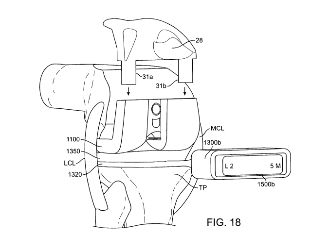
[0105] Fig. 18 shows a perspective view of a knee joint in 90 degrees of
flexion. The
patella and patella tendon have been removed from this view for clarity. A
force sensor
1300b is shown including a force sensing portion 1320 and pad 1350 inserted
between the
tibial plateau TP and the femoral adjustment member 1100. For purposes of
demonstration,
initial force readings of two lateral (L2) and five medial (5M) are shown on
integrated
display 1500b. This indicates the lateral side has less force (i.e. is more
lax) than the medial
side, in this example. The lateral collateral ligament LCL and the medial
collateral ligament
MCL are currently unbalanced. The tangs 31a and 31b of the anterior patellar
groove 28
section can now slip into the femoral adjustment member 1100 through grooves
29a and 29b,
respectively (shown in Fig. 16).
[0106] Fig. 19 shows a perspective view of a knee joint in 90 degrees of
inflexion with the
anterior patella groove section 28 and the patella tendon in place 30.
Although the patella has
CA 02778040 2012-04-18
WO 2011/049637 PCT/US2010/030524
been reduced, the force sensor 1300b displays the same reading, namely, two
lateral (L2) and
five medial (5M) as before patella reduction.
[0107] Fig. 20 shows the wrench tip 32 of screwing tool 450 moving to engage
an
adjustment aperture 31. The adjustment aperture 31 accesses the lateral side
of the patella
groove section 28. Fig. 20 shows the knee joint remaining in 90 degrees of
flexion just prior
to adjustment. The knee remains unbalanced and the screwing tool has not yet
been rotated
to adjust the lateral collateral ligament.
[0108] Fig. 21 shows screwing tool 450 now engaged with an adjustment aperture
31.
Adjustment is accomplished by turning the screwing tool 450 clockwise or
counterclockwise
460 to adjust ligament tension as indicated by the force sensor display 1500b.
In this
example, the lateral side has now been adjusted so the medial collateral
ligament MCL and
the lateral collateral ligament LCL are balanced in tension as can be verified
by the force
sensor display 1500b reading of five lateral (L5) and five medial (5M). By
comparing the
lateral skid space 33 in Fig. 20 (before adjustment) and the lateral skid
space 34 in Fig. 21
(after adjustment), the lateral space has increased to bring the knee
ligaments in balance by
externally rotating the femoral component (i.e. the lateral side of the femur
has been raised).
Anatomically, knee stability originates on the medial side of the knee joint.
Therefore, it is
preferred to register a force reading on the medial side. Sometimes this may
require one or
more shims to be inserted between the tibial plateau TP and the femoral
adjustment member
1100, for example. The lateral side is brought in balance with the medial. If
a reading on the
medial side cannot be obtained even after inserting shims between the tibial
plateau TP and
the femoral adjustment member 1100, the medial structure is incompetent and
the patient is
not a candidate for soft tissue balancing as described herewith.
[0109] Fig. 22 shows a top view of a knee brought into extension by raising
the lower leg.
A lax medial collateral ligament MCL and a lax lateral collateral ligament LCL
are verified
by the force sensor display 1500b reading of zero lateral (LO) and zero medial
(OM). This
reading is also consistent with a noticeable space 34 that now exists between
the pad 1350
inserted between the tibial plateau TP and the femoral adjustment member 1100.
Note that
this space 34 did not exist when the knee was in 90 degrees of flexion and the
ligaments were
in balance (Fig. 21). This space 34 in extension is often caused because the
joint lines in the
primary knee have often been made too far in the proximal direction. This may
result in a
plethora of issues including patella tracking problems, for example. To avoid
these issues, a
26
CA 02778040 2012-04-18
WO 2011/049637 PCT/US2010/030524
correctly chosen augment element thickness is used to close the extension
space 34 and
reestablish the joint line.
[0110] This is done by first positioning the extended leg back into flexion.
The patella
tendon 30 is moved to access screw member 26. An screwing tool 450 is
interchangeably
engaged with a screw member 26 (shown in Fig. 17). The screwing tool 450
rotates to adjust
the intermedullary rod 400. This adjustment causes the rod 400 to move in a
telescopic
fashion out of the intermedullary canal to allow the anterior patella groove
section 28 to be
removed and replaced with a thicker augment element. This provides a shim
between the
backside of the femoral adjustment member and cut C on the distal femur. Thus,
the distal
femoral surface is now butted against the augment element of anterior patella
groove section
28. The leg is placed back into extension to determine if the space 34 has
been filled. These
steps may be repeated until a properly sized augment element has been chosen
such that the
space 34 is closed in extension.
[0111] For comparison, a side view of a patellar groove 28 section without an
augment
element is shown in Fig. 23. Figs. 23A-23C show side views of a series of
three patellar
groove sections with progressively thicker widths 34a-34c of augment elements
32a-32c,
respectively, attached. The augment elements 32a-32c are thickened anterior
patella femoral
pieces. Many thicknesses or combinations of thicknesses may be used and are
not
necessarily limited to these three exemplary sizes. Regardless of the
thickness, the augment
abuts the distal femur. Fig 23A shows a side view of the patellar groove 28a
section of the
original anterior patella femoral piece that was in place when the knee was
balanced in
flexion (Fig. 21). Thus, augment element 32a represents the nominal/minimal
thickness. To
achieve a force reading in extension, a thicker augment will need to be
introduced to fill the
space 34 shown in Fig. 22. The augment elements are loaded into the femoral
adjustment
member with the same two tangs 31 a and 31b positioned on the front of the
patellar groove
section and still slide into the femoral adjustment member in the same slots
29a and 29b. The
augment elements function like shims. They are integral with the patellar
groove 28 section
in this example. Figs. 23A1-23B1 show a side view of Figs. 23A and 23B in
context with
surrounding related anatomical structures and the femoral adjustment member.
[0112] Figs. 23D-23F show side views of an alternative embodiment of the
augment
elements in which they are separately attachable to the femoral adjustment
member 1100.
The augment elements may attach to the femoral adjustment member 1100
magnetically or
27
CA 02778040 2012-04-18
WO 2011/049637 PCT/US2010/030524
slide or clip into place, for example. Progressively thicker widths 36a-36c of
augment
elements 35a-35c are attached to femoral adjustment member 1100 and straddle
the
intermedullary rod 400.
[0113] Figs. 23G-231 show perspective views of yet another alternative
embodiment of the
augment element in Fig. 23E. Fig. 23G shows protrusions 38a and 38b of augment
element
35b sliding in direction 37 into engagement tracks 39a and 39b, respectively,
of femoral
adjustment member 1100. Fig. 23H is the same perspective after the augment
element has
been attached to the femoral member. Augment element 35b straddles the
intermedullary rod
400 and abuts the distal femoral cut C (not shown in Figs. 23G-231).
[0114] Fig. 24 shows top view of a knee in extension. The medial collateral
ligament MCL
and lateral collateral ligament LCL are verified by the force sensor display
1500b reading of
ten lateral (L10) and ten medial (1 OM) indicating that the knee is in balance
in extension (as
well as flexion) and the joint line has successfully been reestablished by
choosing the correct
augment element thickness. The patella tendon comes into balance when the
joint line is
established. This reading is also consistent with the space 34 that has now
been closed
between the pad 1350 located between the tibial plateau TP and the femoral
adjustment
member 1100. While a well balanced knee with an extension space may be
approximately 2x
the flexion space, as in this example, it does not necessarily have to be this
relationship. The
preferred factor is that the medial collateral ligament MCL and the lateral
collateral ligament
LCL are in balanced in tension with lateral and medial force sensor readings
being very close
or equal to one another.
[0115] Once the medial collateral ligament MCL and lateral collateral ligament
LCL are in
balance in extension and flexion and the joint line has been reestablished, a
clean-up cut on
the anterior surface of the femur can be made. The clean-up cut up is taken at
an angle so as
to properly account for the influence of the femoral curve and correct cuts
previously made to
the anterior side of the distal femur in previous knee replacement surgery
procedure(s).
[0116] In the low profile embodiment shown in Fig. 25A, a key 46 is attached
to the
anterior patella cutting guide 50a. Tangs 31a and 31b of the cutting guide 50a
engage slots
29a and 29b, respectively, in the femoral adjustment member 1100 as the
cutting guide slides
in direction 44 toward the femoral member 1100. Fig. 25B shows the key 46
resting on the
outer race 23 of the intermedullary rod 400 with a gap 47 between the cutting
guide 50a and
femoral adjustment member 1100. In this embodiment, the key 46 serves a
similar purpose
28
CA 02778040 2012-04-18
WO 2011/049637 PCT/US2010/030524
as the locking clamp 1200 described in a previous embodiment; however, instead
of choosing
a side of the locking clamp to position higher or lower against a reference
cutting guide, the
height of the key 46 is adjusted to raise or lower the cutting guide. An
example where the
height of key 46 is too tall (i.e. gap 47 is too large) is shown in Fig. 26A.
The cutting guide
50a is positioned too high so that when the blade 48 is inserted into the
cutting guide, it does
not contact bone and thus cannot make a clean-up cut. Accordingly, the
anterior patella
cutting guide 50a is replaced with a new anterior femoral piece 50b, shown in
Fig. 26B. This
cutting guide has a shorter key 51 that produces a smaller gap 49. The cutting
guide 50b
positions the blade 48 to make a nominal clean-up cut on the anterior surface
of the femur.
This nominal cut provides a clean surface to establish femoral component
rotation. By
comparison, Fig. 26C illustrates a scenario in which a very short key is used
that positions the
cutting guide 50c too low. Thus, blade 48 removes too much bone during the
clean-up cut
raising the potential of femoral fracture. The anterior patella cutting guides
may be switched
between key height positions without the need to reconfigure or reposition any
component of
femoral adjustment member 1100 and intermedullary rod 400. The goal is to
guide blade 48
to engage a minimal amount of bone to complete a clean-up cut to reestablish
the rebalanced
rotation but not remove so much bone that the integrity of the femoral cortex
or shaft is
compromised.
[0117] After the clean-up cut is made, the cutting guide is removed from the
femoral
adjustment member and the femoral adjustment member is removed from the distal
femur. A
second cutting guide can be placed on the distal femur to make a subsequent
cut based on the
first cut. The clean-up cut provides a reference to make secondary and/or
tertiary cuts, to
complete the shaping of the distal femur to receive the new femoral component.
[0118] While the above is a complete description of the embodiments of the
invention,
various alternatives, modifications, and equivalents may be used. Therefore,
the above
description should not be taken as limiting in scope of the invention which is
defined by the
appended claims.
29